audioguru
-
Posts
12,026 -
Joined
-
Last visited
-
Days Won
13
Content Type
Profiles
Forums
Events
Everything posted by audioguru
-
When you turn down P2 to zero then the project's output current should be no more than a few mA. The circuit reduces the output voltage with U3 and D9 to reduce the current. When the current is limited to a few mA then the anode of D9 is 0V and its cathode which is driven from the output of U3 must be about -0.65V. That is why U3 is an opamp that has its input and output able to go close to its negative supply and why it has a negative supply. When you turn up P2 then the current does not go up, the voltage and the load resistance set the current. The maximum current goes up. The circuit is designed for a maximum current of 3A so you should set the current calibration trimpot RV3 so that with P2 at maximum and with the output of the project shorted then the current is 3.0A. If RV3 is set to its maximum of 100k then the maximum output current will be 1.33A as I showed in post #?.
-
165mV/500mA= 0.33 ohms that is wrong. 215mV/1A= 0.215 ohms that is also wrong. 1.304V/3A= 0.435 ohms which is close to your measurement of R7. Then trimpot RV3 is set for a max current of 3A or less. When the output current is higher than the setting of P2 then the output of U3 goes low which turns on the LED and reduces the voltage at the output amplifier. Then the shorted output should have a current of 3.0A maximum. The opamp used for U3 and the negative supply voltage must be allow the output of U3 to go low enough so that the input to the output amplifier is shorted to 0V when the output of the project is shorted. Then R7 is the load.
-
I use copper wire, not rice wire. They put rice in everything they make, especially batteries.
-
5V on 10 ohms produces a current of 500mA (0.5A). Then the voltage across R7 is 0.235V. On your schematic, C is the ground for the current regulator. The output ground is its input signal and the 11.2V is its reference voltage.
-
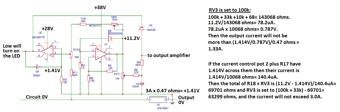
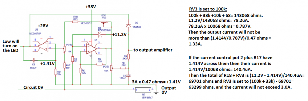
The Chinese meter is messing up the voltage and current of the power supply project. Try the power supply project without the Chinese meter. Measure the voltage across R7 then calculate the current in it. The voltage across R7 will never be more than 1.414V when the current in it is 3.0A or less. Here are my calculations for the current calibration trimpot RV3:
-
Which schematic are you using? Years ago when I replaced the low voltage TL081 opamps with higher voltage MC34071 or TLE2141 I replaced the D7 zener diode with two diodes so that the negative supply is only -1.3V. The 0V reference (zero point) for making measurements has always been the negative wire of C1, the main filter capacitor.
-
Hi Tintin, Now you say you measured 27VAC from your 24V transformer when its load current is low. Then it is cheap and has a high resistance so they made its voltage 27VAC instead of if it had low resistance and an output closer to 24VAC. Or maybe the voltage of your AC electricity is higher than normal. The peak of 27VAC is 27V x 1.414= 38.2V and the full wave rectifier drops it to about 36.8VDC, not 44VDC.
-
This project will not produce 30.0VDC at 3.0A with a 24V transformer. It might produce 25VDC at 2A with a lot of unregulated ripple.The transformer must be 28VAC or 30VAC at 4.2A. A 24V transformer will produce about 25VDC when it has a small load current which has a peak of 25V x 1.414= +35.4V and the bridge rectifier reduces it to about +34.0V. Maybe your transformer is cheap and has a small maximum current so it is made to produce a much higher voltage when it has a small load current (your 2.2k resistors) then its voltage drops when it is loaded with your 1k resistor. Or maybe your meter is measuring the AC ripple that is caused by the value of the total capacitance of C1 is too small.
-
A solderless breadboard has intermittent contacts that cannot handle the high currents of this project. The many rows of contacts and wires all over the place have capacitance between them that frequently causes a circuit like in this project to oscillate at a high frequency. In my career I made all my prototypes soldered together on stripboard where I planned the layout to be compact and the strips were cut to length so that each strip was used for many parts of the circuit. Some of the circuits were very complex but worked perfectly and looked good enough to be sold as the final professional product.
-
Every opamp has an input offset voltage error. Single opamps like the recommended MC34071 and the TLE2141 have input offset voltage adjustment pins. The project uses trimpot RV1 to null the offset voltage but your MC34072 does not have offset adjustment pins. Since your MC34072 has two opamps then it has double the heating and I think it becomes too hot. The original project used the wrong value for R10 connected to RV1 and R10 was connected to the wrong voltage. Here is how it was and how it should be:

-
The Chinese power supply uses relays to switch the transformer voltage into voltage ranges so that the output transistor does not get too hot. I do not know if any parts are overloaded and I do not know how good or bad is its regulation. Its LM741 opamps were designed 50 years ago (!).
-
Your photo of a no-name-brand Chinese power supply does not show any specifications and does not show its schematic and parts list. The photo shows its 30VDC output when its current is zero. The defective Greek kit and Chinese copies do that but cannot produce 30VDC at 3A. Instead they produce about 25VDC with a lot of ripple at 2.5A and the parts are burning.
-
This project has been copied and is available for a very low price on ebay, Banggood and Amazon. But it has all the problems of the original kit from Greece. Many parts are overloaded and fail soon. It does not produce 30VDC at 3A. It looks like the Chinese people who copied it never made it and never tested it.
-
The original project had many overloaded parts including the power transformer. It used TL081 opamps but your TL071 opamps are simply TL081 opamps selected fo low noise (audio applications). Their absolute maximum supply volyage is 36V but this project with a 24VAC transformer produces about 25VAC when the load current is low then its peak is 35.4V which is reduced to about +34V which is the positive voltage for some of the opamps and -5.6V is the negative supply for them. Then they get 34V plus 5.6V= 39.6V which is too high for these opamps so they will fail soon. The improved modified circuit uses opamps rated at 44V and the -5.6V supply is reduced to -1.3V. Of course the output transistor gets hot when loaded, even with a huge heatsink because it and the driver transistor are overloaded. The improved modified circuit uses a better driver transistor with a proper case that can be bolted to a larger heatsink and TWO output transistors are used to share the heat. Use a fan if you want. It is easy to find a table of wire size and the current it can handle, and use Ohm's law to calculate its voltage drop. Use #18 AWG wire and solid core or stranded are both able to carry many amps of current with a low amount of voltage drop. The overloaded transformer is rated at 24V x 3A= 72VA but needs a transformer that is 28V x 1.414 x 3A= 119VA instead then its voltage will not collapse when loaded. But then the 44V opamps must be used. It should be obvious to you that when the current setting is set low (you cannot turn it off) then any load current higher than the setting will reduce the output voltage. It should have excellent voltage regulation. If the current setting is 2A and you load the project with 1.5A then the output voltage might be 25.0V with the load and the voltage set to 25.0V and when the load is disconnected the voltage might rise to 25.005V, or be 25.0V with 2A and drop to 24.095V without a load.
-
No, it is a power supply, not a charger.
-
No, it is a power supply not a charger. Then this modified power supply project will have a maximum regulated output of only about +25V at 3A.
-
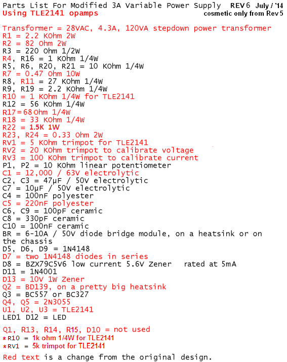
Since it was years ago I do not remember which page of which thread has version 6 or 7. I have the schematic and parts list of version 6 here:
-
The speaker drivers look tiny, 2 inches or 3 inches in diameter like a cheap clock radio? No bass. The PAM8403 amplifier IC produces 3 Whats with high distortion into a 4 ohm speaker per channel or 2 Watts at less but still audible distortion when the supply is 5V. Have you heard the Bose little Bluetooth mono speaker? It sounds great and costs $200.00. Why is your speaker stereo? The speakers are too close together for stereo. If you made a mono speaker with the same size enclosure then the speaker driver can be larger for better bass.
-
The TLE2141 opamp has PNP input transistors so that the outputs work with an input as low as 0V. Then you must pull the input down and not let it float up. Your multimeter pulls the input of the opamp down. The maximum input bias current for a TLE2141 opamp is 2.1uA that tries to pull the input voltage up.
-
The middle opamp in Liquibyte's schematic is the 11.2V reference because it uses a 5.6V zener diode and it has a gain of 2 times. The voltage setting pot R27 is simply a voltage divider that feeds 0V to 11.2V to the non-inverting input pin 3 on the opamp on the right side. The gain of this opamp is 1+ (56k/28.8k)= 2.9444 times so that the maximum output of the circuit is 11.2v x 2.9444= 30.0V. Your middle opamp is messed up since its output voltage is too low.
-
I cannot remember my fix for the "on" voltage spike. If you remove the negative supply then you will not be able to limit shorted output current less than about 0.43A since the transistor that replaces the diode cannot go lower than its max saturated output of about 0.2V. 0.2V/0.47 ohms= 0.43A.
-
Nand, Simply calculate the amplitude of the 120Hz (or 100Hz) ripple that will be produce when the load draws 3A. It won't be regulated with that much ripple.
-
You must change the values of the parts that try to produce volts and amps outputs higher than you will get. You can calculate the maximum regulated output voltage, maximum regulated current and maximum heat produced by the transformer then try adjusting the calibration pots to see if they will limit V, A and P low enough. 24VAC has a peak of 34VDC. Your 24V/3.33A transformer is overloaded with more than 80VA. The maximum output of the circuit will be about 25VDC at about 2.3A
-
Audio amplifiers do not need a voltage regulator or a current regulator. A car radio amplifier is powered directly from the car battery with no voltage regulator but the low current radio parts might use a simple little voltage regulator. 14V at 6A is 84W! One amplifier produces a maximum output of 16W into a 4 ohm speaker then 4 channels make 64W. If all 4 amplifiers are producing 64W then if they are linear they heat with an additional 36W and the current is 7.14W but it does not need to be regulated.