audioguru
-
Posts
12,026 -
Joined
-
Last visited
-
Days Won
13
Content Type
Profiles
Forums
Events
Everything posted by audioguru
-
Maybe the circuit works properly when the coils are raised above the ground.
-

0-30 VDC Stabilized Power Supply 0.002-3 A
audioguru replied to CBETO3AP's topic in Power Electronics
There is (or was) a Greek kit available and today there is a Chinese copy of the Greek kit. The kits have a pcb. If you use a kit then you can cross your fingers and hope that one of its many overloaded parts do not fail soon. -
Your ground wire is too thin so it acts like a resistor that has a votage drop across it. You need a "star" ground that has all grounds together at one point then there is no ground wire for a voltage to develop across.
-
I think the very high discharge current in the ground wire is modulating the 0V of the PWM circuit or the opamp circuit. Use a thicker ground wire.
-
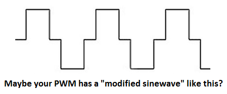
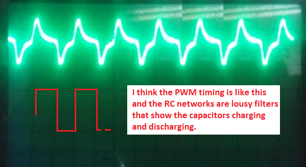
Why are you using poorly filtered PWM instead of variable DC? I don't see any "noise" on the 'scope. Instead I see the filter capacitors charging and discharging. Maybe the signal is a modified sinewave?
-
Your RC networks are lousy filters:
-
The output current is not shutoff when the current exceeds the current setting. Instead the current is regulated to drop to and stay at the setting: 1) Voltage is set to 20.0V and current is set to 1.0A. No load. The output of U3 goes as high as it can, D9 is reverse-biased and does nothing. 2) Voltage is set to 20.0V and current is set to 1.0A. A load of 10 ohms is applied. The output voltage must drop to 10 ohms x 1A= 10V and the output of U3 drops to about +3.13V. The input of U2 is about +3.73V. 3) Voltage is set to 20.0V and current is set to 1.0A. The output is shorted. The output voltage must be 0V and the current must be 1A. The output of U3 drops to about -0.04V and the input of U2 is about +0.56V. The output of U3 will never go below -0.04V which does not harm it since its negative supply is -1.3V. The gain of the voltage amplifier is 30V/11.2V= 2.68 and the output of U2 never goes below about +1.2V due to the driver and output transistors Vbe voltage drops. The non-inverting input of U2 is always at least +1.2V/2.68= +0.45V when the voltage and current settings are zero and there is no load. Many ordinary opamps have inputs that do not work when they are a few volts from the negative supply pin, but the inputs of the TLE2141 work all the way down to the negative supply pin voltage. Isn't the idling current simply the 3.4mA to 4.4mA current of U2? You are correct, U2 gets hot but not too hot. The driver and output transistors need huge non-enclosed heatsinks or a fan.
-
I think with a low output voltage at 5A then driver transistor Q2 will get too hot. I think the three 2N3055 transistors will also get too hot. Opamp U2 also might get too hot.
-
The Rev7 schematic is titled 3A, not 5A. How will you prevent it from melting? If you use a supply for the voltage regulating opamp of only 33V then the project will not supply an output of 30V, it might supply only 25V at full current. That is why we use 44V rated opamps.
-
Can the wind from a fan push a wing that pushes on a changeover switch? Then when the fan is slow or it stops (even if its electrical power gets cutoff) the changeover switch changes the light from green to red. The switches must use diodes and resistors and DC to make an "OR gate". The DC from the OR gate can activate triacs that turn on and off the lights.
-
Use another opamp connected like U3 but with a 10k negative feedback resistor (or any other value if you need more or less gain.
-
I hate it when people copy a schematic and change all the parts numbers around. The original schematic has U3 as the current regulator, U1 as the voltage reference and U2 as the voltage regulator. I kept them on all my updates. Rev7 was drawn by Liquibyte and has U1 as the current regulator, U2 as the voltage reference and U3 as the voltage regulator which is VERY confusing. Even his resistors, capacitors and transistors have different numbers. Instead of you changing the wiring and causing idle current errors and maybe even having hum on the negative supply affecting your voltage readings simply use the circuit's 0V as the meters ground and measure the voltage across the current-setting pot for the current limit setting and measure the voltage across the current sensing resistor as the actual current of the load.
-
The output of opamp U1 must go negative in order for D9 to reduce the input of opamp U2 to near 0V when the output is shorted so that the output current is regulated.
-
Why don't you look at the datasheet that shows both darlington transistors? They are both the same except the TIP120 has a very high breakdown voltage and the more expensive (costs one penny more) TIP122 has an extremely high breakdown voltage. But the voltage in this project is only 12V so either Mosfet darlington will be fine. We do not know how much current your motor uses so it might overload the darlington transistor.
-
0-30 VDC Stabilized Power Supply 0.002-3 A
audioguru replied to CBETO3AP's topic in Power Electronics
I did not look into the transient that might occur when the power is turned on or off. Q1 was originally placed to short the output of opamp U2 because the old TL081 original opamps had a problem called "Opamp Phase Inversion" when an input voltage became too close to the negative supply voltage when the negative supply collapsed first when the power was turned off. It would have caused the output of the opamp U2 to suddenly go as high as it can which is bad for the speaker. The new opamps do not have this problem. You can add Q1 and its resistors if you want. -
Design analog wave generator
audioguru replied to alireza's topic in Electronic Projects Design/Ideas
A square or rectangular wave has a fundamental plus many harmonic frequencies. It is simple to change the phase of one frequency but difficult (a time delay is needed) for many frequencies. Maybe a microcontroller and somebody to program it can be used. -
0-30 VDC Stabilized Power Supply 0.002-3 A
audioguru replied to CBETO3AP's topic in Power Electronics
Many parts are changed or added so a new pcb is needed. Here are the latest parts list and schematic for the improved version: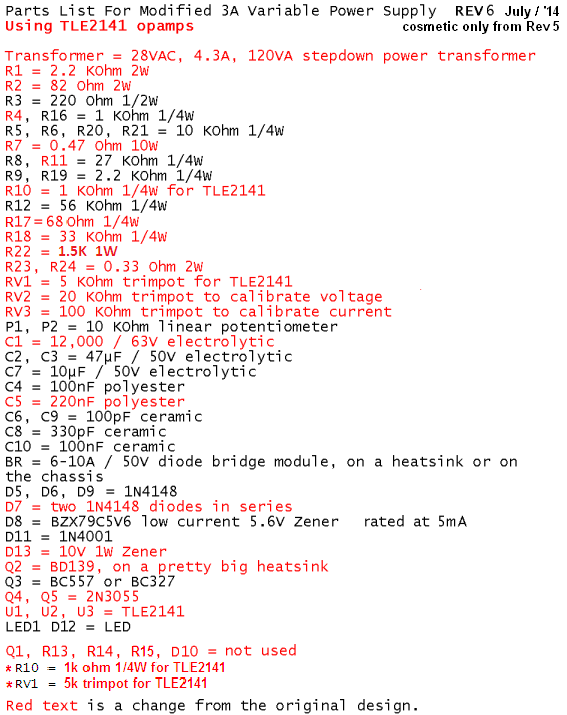
-
Many zener diode datasheets do not show their tempco. These ones do: 1) The 1N5230B is 4.7V and 1N5231B is 5.1V at 20mA but their current is too high for the opamp that doubles their voltage. 2) The BZX79C5V6RL is 5.6V at 5mA which is why I selected it.
-
0-30 VDC Stabilized Power Supply 0.002-3 A
audioguru replied to CBETO3AP's topic in Power Electronics
I have never seen this defective new copy of the original project before. It has all the errors of the original project and added some new errors. The parts numbering has been changed so it is difficult to say that a resistor is 1/4W but must be 1W and its value should be xxx. Many parts are overloaded and the opamps have a total supply voltage too high for them. -
0-30 VDC Stabilized Power Supply 0.002-3 A
audioguru replied to CBETO3AP's topic in Power Electronics
I do not like to look at a pcb that has nothing labelled. -
0-30 VDC Stabilized Power Supply 0.002-3 A
audioguru replied to CBETO3AP's topic in Power Electronics
OZ6YM, Which version of this project did you make: 1) The original Greek kit with many overloaded parts and it cannot produce 30V at 3A? 2) The improved circuit in the forums? 3) The Chinese copy of the Greek kit? -
0-30 VDC Stabilized Power Supply 0.002-3 A
audioguru replied to CBETO3AP's topic in Power Electronics
You got excellent voltage regulation. -
how to construct a mod-60 stopwatch counter?
audioguru replied to goblin85's topic in Electronic Projects Design/Ideas
Nobody uses old fashioned TTL logic ICs anymore. Can you buy them anywhere? -
0-30 VDC Stabilized Power Supply 0.002-3 A
audioguru replied to CBETO3AP's topic in Power Electronics
The peak voltage from a 24VAC transformer is 34V. It charges the main filter capacitor to this peak voltage and heats the load, rectifiers, series pass transistors, driver transistors and current sensing resistor. Then this 300W transformer is at its max current when the DC output current is 8.8A. The inputs of some 741 opamps fail to work when their voltage is within 4V from the positive or negative supply so the 1.3V from the two diodes is not enough. Use the negative -5.6V supply in the original circuit. The LM311 is a comparator, not an opamp. It its voltage gain is 200,000 times and it oscillates if it has negative feedback. Maybe you calculated with "typical" current gain. Then you must buy a few hundred transistors, test their gain and use only the best ones. We usually design circuits so that all of them work well even if the transistors have minimum specs. We do not use "China" transistors or ICs. Instead we use Name Brand genuine parts. -
0-30 VDC Stabilized Power Supply 0.002-3 A
audioguru replied to CBETO3AP's topic in Power Electronics
What will you use to drive the 10 output transistors? 5 or 10 driver transistors that are driven from 5 opamps. Do you really need 30A? For what?