Mandavar
-
Posts
14 -
Joined
-
Last visited
Never
Mandavar's Achievements
")
Newbie (1/14)
0
Reputation
-
Speed-limit Alert PLEASE HELP!!!!!!!!
Mandavar replied to pieterw0's topic in Electronic Projects Design/Ideas
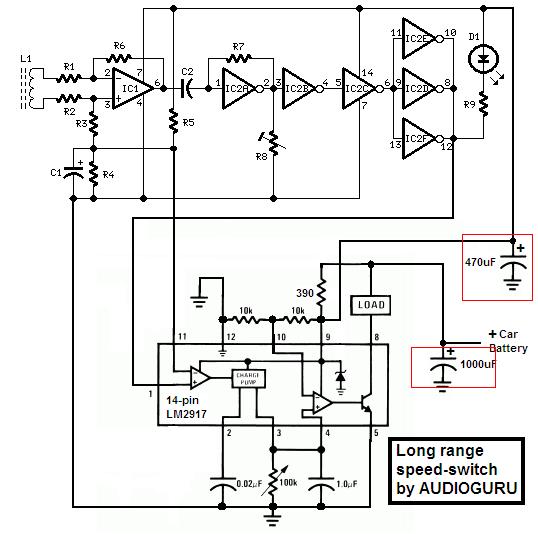
Hi Audioguru in the operation description of this project the author write down that IC2B To IC2F (Cmos Inveters) do a clean pluse squaring to the signal. my qustion is how by inverting a signal we can have a clean pluse squaring operation? And does these inverters further amplifiy the signal besides the inverting? Thanks for your help again -
Speed-limit Alert PLEASE HELP!!!!!!!!
Mandavar replied to pieterw0's topic in Electronic Projects Design/Ideas
Hi Audioguru What effect does R7 do? why its used? ------------------------------------------------- How can we describe by equations the voltage at Pin 2 & Pin3 of IC1 (Diffrential amplifier) --------------------------------------------------- Thanks for ur help -
Speed-limit Alert PLEASE HELP!!!!!!!!
Mandavar replied to pieterw0's topic in Electronic Projects Design/Ideas
Hi Audioguru I have a questions about IC1 (Diffrential amplifier) .. Is the same signal picked up by the sensor coil (inductor) entering the inverting and the non-inverting inputs of the IC1 if yes why is that? and in what mode this Diffrential amplifier is working (Common-mode??) ? -
Speed-limit Alert PLEASE HELP!!!!!!!!
Mandavar replied to pieterw0's topic in Electronic Projects Design/Ideas
Hi Audioguru you told me before that the capacitors can filter out alternator whine and some nosie .. i just wonder how can capacitor do that? and does the filtration improves when we increase the capacitor value? i just want to know the realtion between the capacitors and the filtering thing and how it works.. Thanks for your help again -
Speed-limit Alert PLEASE HELP!!!!!!!!
Mandavar replied to pieterw0's topic in Electronic Projects Design/Ideas
Hi Audiogurur I have another question about the Capacitor C2 that is connected to IC2A which has a feedback R7 does this makes IC2A a Diffrentiator and if yes what is the need of it? And another thing about capacitor C1 What is the main purpose of it? Really thanks for your help you are so helpfull Have a nice day -
Speed-limit Alert PLEASE HELP!!!!!!!!
Mandavar replied to pieterw0's topic in Electronic Projects Design/Ideas
Hi Audiogurur As i know the signal we want to sense its over/under frequency is the signal we obtain from pin 12 of IC2 and connected to pin 1 of (LM2917) my question why Connected pin 11 of (Lm2917) to the end of R5? What is the signal we obtain from the end of R5? -
Speed-limit Alert PLEASE HELP!!!!!!!!
Mandavar replied to pieterw0's topic in Electronic Projects Design/Ideas
Hi Audioguru The Capacitors are shown in the circuit u implemented using LM2917 Check the Attachment the capacitors are shown below
-
Speed-limit Alert PLEASE HELP!!!!!!!!
Mandavar replied to pieterw0's topic in Electronic Projects Design/Ideas
Hi Audioguru I really want to thank you for your help again i really wonder if i can use a Buzzer in the load section so i can get a sound when the Input frequency is larger or equal to (1/2RC) and i need your suggestion about this if its possible... Another question about the (1000MicroF and 470 MicroF) Capacitors, why we are using this Values and why is attached in that postions the same question goes for the two Resistors Connected between pin[9 10 12] I`m really sorry for the amount of questions but i`m really willing to know and understand everything in this circuit becaues i`m intrested in it. Thanks for being so helpfull its so nice to get help from a kind person like you -
Speed-limit Alert PLEASE HELP!!!!!!!!
Mandavar replied to pieterw0's topic in Electronic Projects Design/Ideas
Hi Audioguru Thanks for your help again Actually i`m in need of your help again i hope i`m nt dist. you :) The first one about R8 What effect does this resistor for the signal when changing its value? The second and the last one about the Inverters (IC2) Why two of them connected in series (IC2b+IC2c) While the other three (IC2d+IC2F+IC2E) Connected in parallel? Thanks for your help Have a nice day -
Speed-limit Alert PLEASE HELP!!!!!!!!
Mandavar replied to pieterw0's topic in Electronic Projects Design/Ideas
Hi Audiogurur I have another question about the circuit u implemented using LM2917 (14 pin) .. What if i want to use 9v (PP3 battery) the orginal one in the circuit? Do i need to change anything? If so plz can u help with this...... Thanks in advance for ur help have a nice day -
Speed-limit Alert PLEASE HELP!!!!!!!!
Mandavar replied to pieterw0's topic in Electronic Projects Design/Ideas
Hi Audiogurur First of all thanks for ur greeting :D I tried to read the data sheet but for sorry it didnt help me i still cant understand how we can use this IC3 in such a operation... Is it possible to help me with the operation of IC3A and IC3b and the realation between them and the exernal connections... i really want to understand this.... -
Hi there Anyone have the complete detailed circuit operation of this project? i really want to undersatnd every step in this project spicially the operation of the IC3(Dual monostable Multi Vib) i will be very glade if someOne can help me with this.. Thanks in advance for ur help
-
Speed-limit Alert PLEASE HELP!!!!!!!!
Mandavar replied to pieterw0's topic in Electronic Projects Design/Ideas
Hi all Anyone here can help me with the operation of IC3 (Dual Monostable multi vib) i really need to understand the full operation of this IC in the Wirless Speed Limit alert circuit ... Thanks for help in advance