hubble
-
Posts
46 -
Joined
-
Last visited
hubble's Achievements
")
Newbie (1/14)
0
Reputation
-
Thanks all for the guidance; especially you, Hero999. I replaced the converter ic with the new one and now everything is fine. I think it had something to do with voltage feedback pin of the regulator. Nevertheless, it is working fine now with slightly less efficiency due to not so efficient inductor. Thanks.
-
Here are some more observations: Condition: Capacitor is charged to about 30 V. Case 1: Nothing is connected at the output. Almost same voltage as that of the capacitor. Case 2: Only resistor at the output. I see only 1.5 V at the output with the current remaining unchanged at around 18 mA. When the voltage drops below 26 - 27 V, the output current rises to more than 150 mA and the voltage rises to more than 15 V. Case 3: Resistor with LED at the output. Around 18 mA at 5 V. Similar behavior when voltage drops below 26 - 27 V. Even when the capacitor is charged to, say, 20 V and allowed to discharge, the output current is over 150 mA. So, it has just started discharging but the current is already over the maximum value.
-
Someone around to help me............please?
-
The circuit is designed on a perforated board. However, it is compact in component placement. LTC3639 is very small, so very thin magnet wires (enameled copper wire with almost zero resistance) needed to be connected to its leads in order to be able to have them soldered to other components. And, yes I have already read the datasheet for inductor selection. This is where it is mentioned to use torroid or shielded pot core in ferrite type inductor. I am having one torroid type inductor but I don't know its inductance value nor its core type. PS: Looked at the circuit connections again and found a few stray metal pieces stuck between unconnected points. Removed them and now I notice a completely different behavior. When the cap voltage is 50 V and discharged through the LED and 82 ohm resistor, the current is limited to around 18 mA which is what I am looking for until the voltage drops to around 34 - 35 V when the current shoots up to 150 mA and stays that way till the cap is completely discharged. When it is again charged to around 30 - 31 V, it exhibits the same behavior when voltage reaches to 26 - 27 V. The similar behavior can be seen at different voltage levels in a different charge-discharge cycle. What is this strange behavior? Thanks.
-
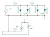
Yes, the inductor is not exactly the same. But, does it have so much affect on the circuit? What other type of inductor can be suitable for this type of application? I have followed datasheet to implement the schematic. I have posted the schematic. Thanks. PS: Can it be because of inductor saturation? If yes, can I use high value inductor?
-
I finished putting together all the components. One component I am not sure about is the inductor. The datasheet mentions to use ferrite pot-cored type which is not available here. Instead, I managed to get the one which looks like as it is shown in the extreme left in this image:http://www.p-wholesale.com/upimg/5/119a1/leaded-power-inductors-698.jpg . Nevertheless; to test the circuit, I connected at the o/p one 3.5 V LED with 100 ohm resistor. The LED lit up only for a few (may be 10 secs) seconds. This was after charging the 10 mF capacitor to 51 V. Noticed the current going way above (twice or thrice) the calculated 15 mA current. I really don't know what is happening here. How do I find the issues with this circuit. Also noted that when there is nothing connected at the o/p, the o/p shows the same voltage as that of the charged capacitor. Is this normal? Thanks.
-
A 100 V capacitor.......sounds good. But then, it should be available here in the milifarad capacity range. I shall try to find it. If I am able to get this, shall I need to connect this capacitor directly to the input pin of the converter? In the datasheet, there is a small 100 V cap across the input. In my case, there is already going to be a big capacitor. Do I need add something more? Thanks.
-
I would have wanted it to last for as long as it can. But for this prototype, the requirement is under 120 sec. Yes, I am. Once the capacitor is fully charged then only the load is going to be activated. Shall I directly connect the capacitor to the input of buck regulator? Thanks.
-
Earlier, I planned to use super capacitor of 2- 5 F 2.7 V. However, these capacitors are very expensive here, if available at all. Instead, high voltage mF caps are readily available. It is because of this reason the generator voltage is needed to be raised to high voltage of around 50 V (safe limit for a 63 V cap) to store considerable amount of energy and then the cap voltage is brought down to sub 5 V level using a high efficiency buck converter. This cap is intended to supply 20 mA max current. Thanks.
-
Ok, I understood it. I have one more situation. How do I connect this capacitor to the LTC3639 buck converter. Does it need to be directly connected to Vin? Also, how to select components to get the desired output from this converter apart from 3.3 V, 5 V? Thanks.
-
I am not able to understand the point of using transistor here. Can I not just connect the 10 mF capacitor across the zener diode to charge it? Thanks.
-
Thanks for your response. Can I use 50 - 51 V zener diode after the voltage is rectified? Won't I be wasting lots of energy in the process? I shall try to find the 230 V to 24 V transformer. Thanks.
-
I apologize for delay in getting back. Actually, my mom met with an accident so I had to take care of her and couldn't do any other work in these 20-25 days. But, now she is recovering well. In the meanwhile, I dropped the idea of using voltage multiplier and instead thought of using transformer. I had a 230 VAC / 12 V 200 mA adapter. Took a transformer out and connected the secondary coil to the stepper motor and measured the output at the primary: the rectified output was around 85 - 90 V. Upon connecting 22 kohm resistor, the output dropped to around 50 V. Can I use this transformer to safely charge a 63 V capacitor to 50 V? Thanks.
-
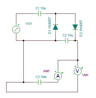
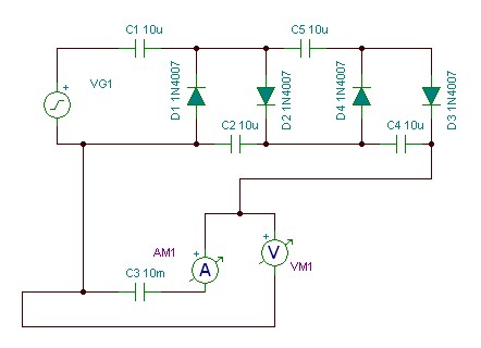
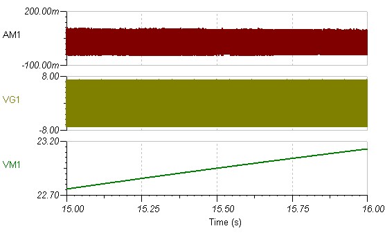
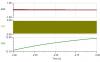
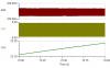
After days of trying to choose between different ways, I chose to go with the CW multiplier. Tried to charge for more than 30 sec with 1n4007 and 10 nF cap system, the 10 mF cap got charged to only 500 mV. I think I have chosen wrong value cap. Here, I tried to simulate with 7 VA 800Hz source, and different stages of 10 uF cap and 1n4007 in TINA, got this result as shown in the attachment. Where am I going?
-
Thanks for providing the link and the equation. However, can boost converter be used here in this case after rectification to raise the voltage to something around 25 to 30 volts and then use multiplier?