Hero999
-
Posts
2,433 -
Joined
-
Last visited
-
Days Won
1
Content Type
Profiles
Forums
Events
Everything posted by Hero999
-
You won't find them, because they're illegal all the good ROM sites have been shut down. The only place to get them now is bittorrent.
-
My criticism was aimed more at not showing the gates inside the box, than drawing it that way to help you to lay it out. I've corrected the resistor values. The wattage can be calculated by looking at the voltage across the resistor and applying Ohm's law. P = V2/R So for R3 P = (4.5-1.2)2/82 = 3.32/82 = (3.3*3.3)/82 = 9.9/82 = 0.121W 4.5 is the power supply voltage and 1.2 is the voltage across the LED. The duty cycle is only 1% so the average power is much less. So a 1/8 W or 1/4W resistor will do. The other resistors used in the circuit use much less power so just use whatever power rating you can get hold of. Tolerance is also unimportant as you're not bothered if the flash rate is different, standard 5% tolerance metal or carbon film resistors will do. Capacitors tend to have a larger tolerance anyway which will swamp the resistors.
-
To allow one 555 to control another you're better off just connecting the output to pin 4, rather than switching the eintire power supply. Don't worry about the power spike, it's unavoidable and is caused by the fact the transistor can't turn on/off instantaneously. It's not a problem because it lasts for such a short length of time it won't overheat the transistor, even if it exceeds its maximum rating.
-

ILL PAY$$$--NEED HELP TO DRIVE 35-40 SMD RGB LED
Hero999 replied to makavelly001's topic in Electronic Projects Design/Ideas
Reading through what you've posted again, you can connect the LEDs in parallel but each one needs its own series resistor. What's the power supply voltage? Note that the LED forward current specified is normally a maximum value, you should limit the current to less than that. The formula for calculating the correct series resistor can be found using Google. You need to experiment to find the required forward current through the red, green and blue LEDs by using variable constant current sources and adjusting them until it produces white light. Then you can work out the correct resistor values. A constant current source can be make with a couple of transistors of the LM317. -
I've had a look at it. You'll notice that the pin numbers for op-amps are not normally shown on schematics. This is because you can use any gates in the package and what connection goes where will depend on how you lay out the PCB, i.e. whether you're using SMT parts or through hole,strip board or a propper PCB and if the circuit as part of a bigger project. I didn't check every single connection but I when added the gates, the inputs and outputs seem to be correct. There are some other errors though: The values of two resistors are wrong: you missed off the k. The input of the unused gate is not connected to either +V or 0V. That's also not the best way of doing it. You should never show an IC as just a box because the schematic doesn't make any sense without referring to the data sheet. The best way of doing this is to add pin numbers to the schematic, as per my previous example. Then as you assemble it, you tick off each pin number as you put the connections in place. I always connect the power supply pins and inputs of the unused gates to either +V or 0V first, before doing anything else. I suppose I didn't make it easy for you by not tagging each component. Attached is your schematic with corrections and the original with tags added. Note that I've not checked everything, go though it and check it again before building it. Low_power_IR_gate_flash_#1.pdf

-
You're very lucky. We do get quite a lot of spam. Fortunately I or another moderator must've deleted it before you saw it.
-
ILL PAY$$$--NEED HELP TO DRIVE 35-40 SMD RGB LED
Hero999 replied to makavelly001's topic in Electronic Projects Design/Ideas
The specification doesn't make any sense, Amps is the unit for measuring current, not capacitance. Does it boost the voltage? The maximum LED voltage is specified at 35V but the maximum input is just 30V. LEDs should be connected in series not parallel. Does the controller limit the current? If so, 10A is far too hgih for those LEDs, if not you need a series resistor for each LED. -
That's exactly what my circuit does. Except a 20% duty cycle is still too high for decent battery life which is why I chose a duty cycle of 1% and to lower the current to 40mA, which should still be enough to activate the emitter.
-
Don't give up too soon it's not as complicated as it seems. The circuit is actually very simple. If you can build the circuit attached, you should be able to build the other circuit fairly easily. It's also pretty easy to explain. A Schmitt trigger is a logic gate with two trigger levels, one to turn on and the other to turn off, I'll explain later. The circuit shown below uses a NOT gate, also known as an inverter. The output is opposite to the input. When the input is 0V, the output is +4.5V and when the input is +4.5V, the output is 0V. The Schmitt trigger has hysteresis (memory). When the input voltage falls below 1.4V the output will go on but it won't go off again until the input voltage rises above 2.38V, now the input won't go on until the input voltage falls below 1.4V. This capacitor is connected to the output of the Schmitt trigger via a resistor and the input connected to the capacitor. When the power is first applied the voltage on the capacitor will be 0V so the output will be on, the capacitor will charge via the resistor, until the voltage on it exceeds 2.38V upon which the output will change to 0V. The capacitor will discharge back into the output via the resistor until the voltage drops below 1.4V causing it to turn back on again and the cycle repeat indefinitely. The oscillators in the previous circuit work on the same principle but include diodes and other reisstors to control the duty cycle. I'll explain more if you're interested.
-
I use LTSpice too, it's a good program.
-
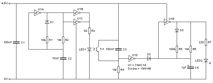
Here's my idea. The LED current is 11mA but it's pulsed at 10% duty cycle at just under 1Hz. The emitter current is 40mA and pulses at about 1% duty, (I didn't bother calculating the frequency, ballpark 100Hz). Note that two gates have been connected in parallel because each one is only capable of suppling 25mA. The input of the unused gate should be connected to either 0V or +4.5V. Refer to the datasheet of the 74HC14 (this can be found uding Google) for the pin out. This should last a couple of months with a fresh set of alkaline AA cells or longer if the detector is exposed to sunlight so the LED will be off during the day. The circuit could be powered from AAA cells charged from a solar panel.
-
It depends on what the resistor does. If it's something like a a current limiting resistor in series with an LED or transistor's base then it's not critical so you can go 10% either way but if it's in a potential divider which determines the output voltage of a regulator, such as the LM317, it's more critical. If you don't understand the schematic then use the exact value or seek advice from someone who does. Anyway I think at least having a basic understanding of a schematic should be a prerequisite for building it.
-
If depends on the day length and light intensity on the shortest darkest winter day and the size of the panel. I suppose you could put the IR sensor in a position where it receives daylight it'll save power by not working when it's not used during the day. I have an idea of how it can be done and will draft a schematic tomorrow, when I have time.
-
Where do you live? Here in the UK I use RS Components (not to be confused with RadioShaft), Farnell and Rapid Electronics.
-
Thinking about this more, you'll never get that kind of battery life from AA cells. Your circuit draws 150mA continuously and the flashing LED draws 35mA pulses at presumably 50% duty cycle making the average current draw 150+35/2 = 167.5mA. http://data.energizer.com/PDFs/l91.pdf A standard AA cell will last just 45 hours with a load of 50mA and discharged to 1V (3V total for your circuit) and an expensive lithium AA cell lasts 60 hours under the same conditions. Your circuit draws over three times that current so it won't even last for a third of the time. You need to use C cells and make changes to the circuit to reduce the current drawn, the duty cycle of the flashing LED and pulse the emitter at a low duty cycle too, rather than keeping it continuously on, which wastes power. This could be done using the 74HC14 hex Schmitt trigger IC.
-
Hi, welcome to the forum.
-
You could try illegally downloading them from a bittorrent site.
-
RD doesn't draw much current so is immaterial. You won't be able to get that kind of battery life at a reasonable brightness from AAA cells.The only way is to use a CMOS oscillator to flash the LED for 0.1s per second (10% duty cycle) but not with a flashing LED which will flash at 50% duty cycle.
-
The second circuit is still wrong. My comments below only refer to the first circuit which will work. RB isn't required because RD will limit the current through the transistor's base. The values for emitter and LED current given on the data sheet are maximum ratings and it continuous operation under them doesn't do the components any good. The emitter current only needs to be high enough to activate the detector and the LED current only needs to be sufficient to give adequate brightness. Try increasing RE to 220R, RD can be 10k and RC can stay as it is or reduced if you want more battery life.
-
The first schematic won't work because the emitter and detector are connected backwards. The second schematic is even worse because all the components are connected backwards.
-
It looks like Filipino to me.
-
You can any voltage solar pannels you like as long as you can buy a suitable grid tie inverter. As a general rule of thumb, it's better to use higher voltages because the current will be lower so you can use thinner cheaper cables. Of course though, higher vottages are more dangerous. With DC serious shocks are unlikely at votlages below 60VDC and voltages below 120VDC pose a fairly low risk of electrocution. As a general rule DC is safer than DC for many reasons.
-
Yes, it's annoying when that happens which is why I generally write no more than a couple of lines for the first response to a thread like this. In this case I posted the schematic for your benefit as much as anyone else's.
-
Yes, the capacitors provide AC coupling so no DC flows through the water. I notice you've attached a datasheet for the TTL/LS 7414. This circuit will only work with CMOS gates because they have a high input impedance. It won't work with older TTL gates because their input impedance is too low. If higher voltage operation is required you could use the CD40106 or 74C14 which will work up to 15V.
-
The cork idea is a good one. Doing it electronically is more complicated. Here's an idea which should work in an automotive situation where the water is already connected to the vehicle chassis.