mendimano
-
Posts
59 -
Joined
-
Last visited
Content Type
Profiles
Forums
Events
Everything posted by mendimano
-
So what do you sugest? to change the voltage regulating potentimeter? and should my voltage regulating potentimeter bring down the voltage to 0 no mater in what position is my current regulating potentimeter?
-
Dear Guru, i have tested and tested the power supply (5 amps version) and everything works perfect, i can bring down to 0 output voltage only when im bringing down to 0 the current potentiometer ( current limitng LED is on), is it OK?
-
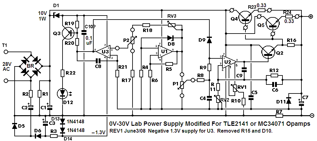
I have TLE2141 OP amplifiers
-
I have replaced C7 from electrolit type to film capacitor ( see attached datasheet) and conect the two paralel 6.8 Kohm resistors to discharge the C7, but still cant bring down the output to 0 still reading 1.1 volts when voltage potentiometer is set to 0 . v735p.pdf
-
Each resistor is dissipating only 2A squared x 0.56 ohms= 2.24W. So its OK to get hot? RV2 is adjusted for an ouput voltage of 0.0V when the voltage pot P1 is set to zero. RV2 is supposed to adjust only about plus or minus 0.05V to cancel the amplified input offset voltage of U2. C7 will hold a voltage if there is no load. is it OK to adjust with RV2 to have 30 volts at the output without no load? Maybe a 3.3k 0.5W resistor should be added to the output to discharge C7.
-
Hi i have just finished the 5 Amps version of the power supply , and it looks like work OK, i have loaded the P.S with 40 parallel connected bulbs ( 26 volts 100mA) and the voltage drop is only 0.1 volt when the current limiter is not on an the voltage drop is 0.5 volts when the current limiter is on, the R7 gets hot with this load ( 2 parallel 7 watt 0.56 Ohm resistors), output transistors (3x MJ11016) are a Little bit warm, as far as voltage i have problem to bring it to 0 when potentiometer is at 0, i get 1.1 volts i have electrolyte capacitor for C7 I'm thinking to change it to film type when I'm adjusting the RV2 so that at output i could have 30 volts I'm having 1.1 volt when I'm bringing the potentiometer to 0 and when I'm bringing down the RV2 voltage drops from 1.1 volts to 0.8 volts at the output with potentiometer bring down to 0, but then at the outup iw got 26 volts with the potentiometer put on maximum. Guru how much should be the value of resistor that i should put at output so to bring the voltage to 0
-
I dont have accses to attachments...why?
-
when im clicking on a links posted for yhis project im geting Error 404 file not found.
-
My unregulated supply voltage is 41.2 Volts, I'm using TLE2141 op amps, and a 30 volt 10 amps transformer, and a BD139, 2X parallel 10.000 uF 63 capacitors for C1 3 parallel connected output transistors MJ11016 with 0.33 ohm 5 watt resistors connected at the emitter each of them, i have made my own PCB i think maybe i have done some mistakes there, i will try to redo the PCB from teseract so can fit my components. BEST REGARDS
-
Thank you audioguro for this detailed instructions on how to test the power supply, by the way U1 and U3 op amp are getting hot (U1 a Little bit more) is that normal without any load on power supply, only the voltmeter at the output.
-
I have finished the power supply 5 amperes version according to attached schematic and parts list, i have measured the output voltage it is 40 volts voltage potentiometer works fine i can bring it to zero voltage, as far as current pot it turns on the LED shortly after i increase the current regulation pot,( is it OK?) PS_Parts_List_10-11-091.pdf

-

Darkroom timer V2.0A project question ????? (Solved)
mendimano replied to guizmo's topic in Projects Q/A
Hey Guizmo how did yu removed the flux?? :D -
Thanx Audioguru for that clear answer, im posting the photo of heatsink that im planing to built, what do you think is it big enough? or stil i have to put some fan (fans) to reduce enough heat from tranzistors
-
Hi to everyone, I'm planing to build an 5 amps version, with TLE2141 and 3X MJ11016, first question to audiguru how many MJ11016 to use , 2 or 3, and my transformer has an output of 31 volt AC without a load i was wondering is it to much is there some risk for OP amplifiers ( with 31 AC) and finally i have 2 capacitors with 10.000 mF should i use them both or one is just enough. Im planing to build acording to this schematic and scech. PS_Parts_List_10-11-091.pdf

-
I have 12 IC TLE2141 , im redy to trade for other electronic components active or pasive, please post any ofer
-
Big knob? can you explain audigur a litle bit the meaning of big knob ;D (sorry), and does this mean for bouth current and voltage
-
im posting the pcb and layout in acordence with audiogurrus schematic, im caling every one on noticing me about mistakes and any sugestions layoutpcb.rar
-
i want to say thanks to tesseract for this god work, now im thinking to build this modified version.
-
thanx for tip to get TLE2141, please if someone has build the 5 Amps version to post his experience, first of all what kind of tansformer to use ( mine is 30 volt 8 amps) will it be enogh for 5 amps version
-
-
Hi Audioguru, as i sead earlier i have decided to build the modified version with this parts list and schematic, please if you have any new ideas and version to post it beafore i have start to buy parts, rgr PS_Parts_List_10-11-09.pdf
-
I think tat is a great idea from jure, if any one havs the gerber file of pcb from the original version we colud modified for the latest version, so im caling to anyone if havs the gerber file to post it, regards
-
Thanx again Redwire, since i have two capacitors of 10.000 mF 63 Volts can i conect them paralel and use them
-
P.S this schematics ;D
-
Thanx Redwire :) i will veate litle bit more for any post fom audioguru beafore i start building the power supply, tell me if this part list that you have posted goes with this schematics, and if you could tell me some other tips and sugestions since im planing to build an 5 amps version. Regards ;D