

HarryA
-
Posts
453 -
Joined
-
Last visited
-
Days Won
24
Content Type
Profiles
Forums
Events
Posts posted by HarryA
-
-
The only way I can think of to do that is to use two circuits. First a frequency to voltage converter circuit. Then feed the voltage output of that circuit into a voltage to frequency converter circuit. One can find such circuits by searching on the internet. A circuit simulator would be helpful here.
The 9400 chip can be used as a voltage-to-frequency or frequency-to-voltage converter. Perhaps there is a newer chip?
Hopefully someone else will have a better idea for you 😐 -
The vertical green line supplies current to the transistor. The other part of the green line supplies current to the detector which modulates it to form the audio and afc outputs.
-
On my forum if you replace http: and keto one can at least alert guests not to click on the links and that may help. At least it is not difficult to implement.
from my forum (note spaces around SPAM and SPAMMER - helps them stand out):
Put the word to be censored on the left, and what to change it to on the right.
http: => SPAM
KETO => SPAMMERgiven: http://www.badguy.com => SPAM //www.badguy.com
this is keto crap => this is SPAMMER crapMembers posting url's in a post would learn to use the short version without the http: www.rcgroups.com
Is spam the correct word or does that only apply to emails?
-
You could ask for help finding a schematic here - maybe helpful:
http://www.fixya.com/support/p143760-mge_pulsar_evolution_2200_esv22_ups
Good luck.
-
the manual is here if that is helpful:
https://www.manualslib.com/products/Mge-Ups-Systems-Pulsar-Esv-22Plusrack-1938198.html
-
If you open the register page and right click on the page and select "view page source" you see the html code that makes that page. If you search on that code for: "form_q_and_a" you will find the block of code that renders that area on the page.(in firefox search by ctrl+ f) and that contains your question. If one is comfortable with working with files on the server one can find the file that contains the "form_q_and_a" string. then download it to your pc and replace the text string with an image ( jpg or png file ) of the text in mixed colors and fonts.
If you don't have the tools to create such a file I do. You may not see you text string in that file as it maybe added in at run time.
In my first forum I got to the point that I would register members via an email request myself; they where not allowed to do so. I used their requested user name and assigned them temp.password and that works well if you do not have many request per day. It beats having to clean up the forum everyday.
-
In the world of electronics what is a "landing deck"? I only know of landing decks on aircraft carriers and at the foot of stairs.
I am guessing it is where you "land" your cell phone.
-
Can the bad guys login via "Sign in with Twitter or Linkedin" or Anonymously thus avoiding the question?
-
To start with those capacitors are 4700 microfarads (not 4.7) at 400 volts, not cheap. The resistors are 50 watt resistors.
I would think the yellow leads on your transformers are taps, here unused. If you connect two of the output black wires together and measure the voltage across the other two you should get 220 volts rms. If not select a different wire for one of then. You must have at least a inexpensive multi-meter to work with.
Beware these are high voltages and those large capacitors hold enough current to do you in!
-
Something like what is the: "unit of capacitance"a five letter word". It is only a slight inconvenience at most for real people plus they only have to do it once.
I set up a forum earlier this year and asked the local padding group if they wanted to use it but they decline. I did not do anything with it for a few months until I got an error message via an email. When I looked at it I had 6800 members, 90% were Russian. As I could only delete 30 members at a time it took awhile to get rid of them.
-
I think your registering question is weak. I would ask a question that requires a Yahoo search. Perhaps the spam computers could not do that.
Like what is Pi to the 6th decimal place?
-
Why don't you all use the spam prevention tools?
https://invisioncommunity.com/features/spam/
On my forum one must answer a question that any kayak or canoe paddler would know to register. Got read of the damn Russians!
-
Without a circuit diagram it is very difficult to help you. You can find numerous videos on youtube.com related to "EGS002 " that maybe helpful. Good luck.
Looks like I was born under the sign -V (I talk to much?)
-
Hello, You could use a rs232 to ttl converter that you could connect to an Arduino microprocessor, You can get the converter for 1$, Arduino from 10$ to 30$ depending on the quality you want. Also you need a power supply about 10$ and a relay about 5$, Plus connectors.
Many of us can help you with the software. I just got a large memory Arduino for 10$ that I am using for a talking weather station.
-
Your circuit is basically incorrect. The DIAC , labelled TRIAC1, would never carry the load in that type of circuit! Only the gate current for the TRIAC.
see the circuit at: https://www.electronicshub.org/simple-fan-regulator-circuit/
for example. Good luck.
-
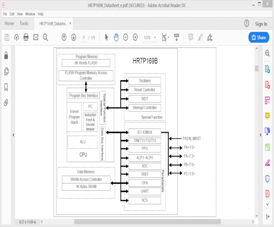
As only the CPU has access to the flash memory I would think it would not be possible to access the code. If it were on a separate chip you could read it with the right equipment. It may be better to develop your own code rather then try to reverse engineer this device.
 chip you
-
If you look around on ebay or amazon.com for "audio amplifier board 5 volts" you may find something that would be helpful. Like:
Icstation PM2038 2X5W stero audio amplifier board 5v USB powered adjustable volume. They are quite inexpensive.
Sorry I can not be more helpful.
-
BMS 18650 chargers are quite inexpensive off Ebay if you are not big on rolling your own.
-
If you search on YouTube for " 3 phase electric motor control" you may find some information that maybe helpful.
-
Perhaps the chip is over heating with to much current draw? Try connecting only two motors to see what happens.
For the l298n chip itself:
For the IO Peak Output Current (each Channel)
– Non Repetitive (t = 100ms) 3.0A
–Repetitive (80% on –20% off; ton = 10ms) 2.5A
–DC Operation 2.0ATOTAL DC CURRENT UP TO 4 A
-
18 hours ago, Deanne said:
R = 400, C = 0.1 F , L = 0.1 H.
I do not see your question; perhaps I am missing something

-
If you are not big on building your own transformer look at:
http://www.surplussales.com/homenew.html#Transformers
example; 95VA Toroidal Transformer 117/234V to 2 x 15V or 30V at 3.2 Amps
at 230 v that would give you say: 14.7 volts; a fat resistor would remove the 0.7
")
-
if:
Vp = primary voltage, Ip =primary current, Np = number of primary windings.
Vs = secondary voltage, Is = secondary current, Ns = number of secondary winding.then: Vp = Vs(Ns/Np) and Ip = Is(Ns/Np)
example: To transform 120 vac to 12 vac,
Vs = 120 vac (100/1000) = 12 vac Ns/Np = 0.1, say 100/1000Using Ip = Is(Ns/Np) I am not clear which way you are going here.
0.3 amperes = 1 ampere (Ns/Np) Ns/Np = 0.3 say 180/600
or: 1 ampere = 0.3(Np/Ns) Np/Ns = 3.33.. or say 600/180
For power: Pp = Ps at 100% efficiency.
Ps = n * Pp where n is the efficiency factor. n between 65 and 99 percentFor 50 watts at the secondary and 75% efficiency the primary power would be:
Pp watts= Ps/n = 50 vac/0.75 = 66.66... watts.For Impedance: Zp = Zs(Np/Ns)^2
To connect an 8 ohm speaker to a 400 ohm amplifier:
Np/Ns = (Zp/Zs)^0.5 = (400/8)^0.5 = 7I must confess I have no idea how many windings real transformers have; do not go by my numbers.
Somewhere I have a book that has information on designing transformers if you need more info I will try to find it.
-
I would think if the larger rated relays failed then the smaller rated relays would not last as long.
Have you tried looking on Ebay for replacements? I have had good luck recently finding replacement parts on Ebay.
Sorry I can not be more helpful to you; good luck.


Sine wave frequency multiplier
in Projects Q/A
Posted
That is a good idea but how do you get the divide by 2.7 required ? Is the best one can do is to divide by 5 then by 2 or 10 and 4 for 2.5 perhaps.
There is a good phase locked loop frequency multiplier tutorial at: www.youtube.com/watch?v=5by0os8RrFY