

HarryA
-
Posts
466 -
Joined
-
Last visited
-
Days Won
24
5 Followers


HarryA's Achievements
")


-
https://www.alldatasheet.com/view.jsp?Searchword=M88CS8001-S000
-
There is some good information on using Arduino boards and Bluetooth in the Arduino Cookbook. It can be download free from; Cookbook One can use a Bluetooth enabled PC for testing I believe. The pairing address from the table saw would be needed I gather. The Arduino board to the vacuum cleaner can be done with a simple transistor circuit driving a relay as an on/off switch. If you need further help do not be afraid to ask.
-
I will message you a temp email address. You could try sending me an email with your LTspice .asc file as an attachment. I could play with it. If I can figure how to do messaging.
-
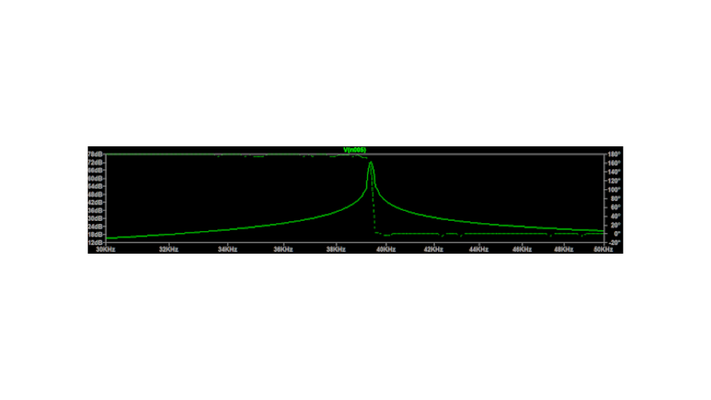
Try this. On your schematic window click on a blank area. Select Edit Simulation CMD then in the popup dialog box select AC Analysis. Select Linear or Decade(?) . Then I used: 500, 30k, 50k. Next click on the signal symbol and set then AC voltage to some value. On running the simulation I got a peak at 39.36k. Your schematic is further along then mine so you should get different results. I used the 53000u for the capacitor. This guy uses a different approach but I can not follow him Ltspice video
-
I think you would find this free Power Electronics course from MIT very helpful. The math is not to bad 😉 I find it very interesting. There are 38 lectures in all; by the end you have a good understanding of power circuits. Power Electronics
-

why can't a mosfet be directly driven by a microcontroller?
HarryA replied to vbsemi's topic in Power Electronics
I think the post is worth reading. So lets try Google translator: First, microcontroller I/O ports have limited load capability, typically allowing about 10-20 mA of current. Therefore, they are not usually used to drive loads directly.First, microcontroller I/O ports have limited load capability, typically allowing about 10-20 mA of current. Therefore, they are not usually used to drive loads directly. https://youtu.be/pbz5aMdxSEU First, microcontroller I/O ports have limited load capability, usually allowing about 10-20 mA of current. Therefore, they are not usually used to drive loads directly. image.png.4e399c62899257b83f0e2103daa204e1.png Let's briefly compare the differences in driving BJTs and MOSFETs. Bipolar Junction Transistor (BJT): BJTs are current-controlled devices. As long as the base-emitter voltage (Ube) exceeds the threshold voltage (usually 0.7V), the transistor will turn on. For BJTs, 3.3V is definitely greater than Ube, and the base current (Ib) can be calculated as \( Ib = \frac{(VO - 0.7V)}{R2} \). By connecting an appropriate resistor in series with the base, the BJT can be operated in saturation. Microcontrollers are usually targeted for low power consumption, so the supply voltage is usually low, around 3.3V. MOSFET: MOSFET is a voltage controlled device. The gate-source voltage (Vgs) must exceed the threshold voltage to turn on, which is generally around 3-5V, and the saturation drive voltage is 6-8V, which is higher than the 3.3V of the I/O port. If driven with 3.3V, the MOSFET may not be fully turned on or operate in a partially turned-on state. In this state, the MOSFET has a high internal resistance, which limits its ability to handle high current loads, resulting in increased power dissipation and potential damage. Therefore, it is usually better to use a microcontroller to control the BJT, which in turn drives the MOSFET. Why use a BJT to drive a MOSFET? This is because BJTs have lower load capabilities compared to MOSFETs, making them suitable for control applications. Can MOSFETs be driven directly? While it is possible with some low power MOSFETs, it is generally not recommended for larger loads. -
I once had an amplifier that played music with no inputs. It turned out that it was a local am radio station; the results of poor grounding. If you have a wee soldering iron try resoldering the ground on the TL082 op amp. Perhaps that will help.
-
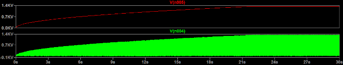
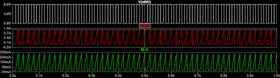
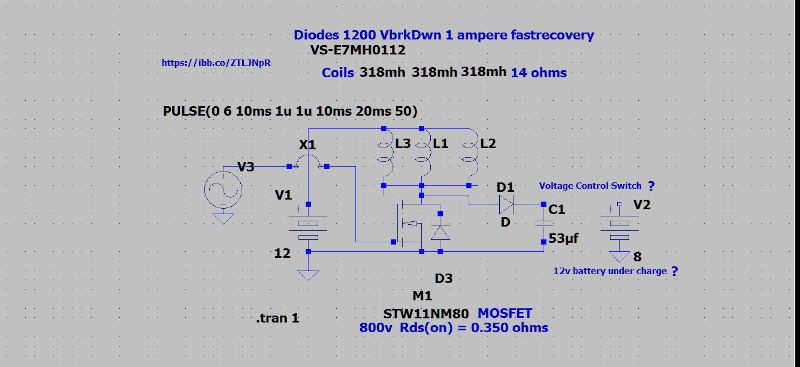
The results from the LTspice simulation. Beware that sometimes the simulators lie. In the first plots the the red line is the voltage across capacitor c1. The green line is the voltage at the mosfet drain. The voltages peaks at 1.34 kv in 24 seconds. The green plot is solid as it is maded up of pulses. The breaks in the red plot are do to the scaling in the Gimp image processing software. In the next three plots; the white plot is the input to the mosfet. 6v peak, 50hz, 20ms high and 20 ms low. The red plot is the current from the mosfet; at 0.905 amperes. While the green plot is the current through one of the coils at 0.301 amperes. Attach is the circuit as used in the simulation. Using components close to the original circuit that the simulator has.
-
I put that circuit into the LTspice circuit simulator but the simulator is not happy with it. I will try later to get it to work. The simulator would give insight into what the currents look like.
-
"After swapping the terminals to the preamp, the hum moved to the other channel." Would not this suggest the problem is in the preamp?
-
Yes, I have had problems uploading with long cables. Never with the short blue cables. I see on Arduino forums others have problems unloading with longer cables also. One has to be aware some "USB" cables are for charging only; they lack the center two data contacts. You can look into the larger connector and see if there are 4 contacts or not.
-
I use the Arduino UNO everyday. It is well supported on the internet at various forums. It is somewhat dated but a good beginners microcomputer. You can download the Arduino IDE 2.0 (integrated development environment ) from arduino.cc The Arduino Cookbook in pdf format is available for download here: Arduino Cookbook If you get an UNO also get the short blue cable; long cables do not often work well.
-
By positive flank you mean on the rising edge of the pulse or the pulse top? What is the nature of the pulse train? Voltage and pulse rates. "Need a circuit that can trigger a relay when movement or stop is detected on a axle." How does that relate to the pulse from the timer being on only 0.5 secs? Does that mean that if the pulse train is off for more than 0.5 seconds (axes stopped turning) the timer drops out resetting the relay? A retriggerable timer would stay on while it is constantly being reset else if not reset after 0.5 secs its output would go low. . For TTL logics datablade books see ebay.com Or even better Forrest Mims's book "Engineer's Note Book !! - A Handbook of Integrated Circuits Applications" is available online in pdf from: IC Book Dated but still the best book ever on ICs. The book has an NE555 circuit for missing pulse detection; which maybe what you need.
-
Will the first circuit here do what you want to do? Fading LED circuit. I tried it in the simulator but I have not got it to work yet; poor connection 🤨
-
 learner6587 reacted to a post in a topic:
A dimmer does the job but is not periodical without the human hand turning up and down the knob constantly.
learner6587 reacted to a post in a topic:
A dimmer does the job but is not periodical without the human hand turning up and down the knob constantly.
-
You say: " one wanted the current to rise lowly from 5 volts to 10 volts each ten seconds," Is 5 volts off for the lamp? Also you all say: "had its light intensity decreasing to zero volts:" That statement is confusing; which is going to zero the light intensity or the applied voltage?