

HarryA
-
Posts
453 -
Joined
-
Last visited
-
Days Won
24
Content Type
Profiles
Forums
Events
Posts posted by HarryA
-
-
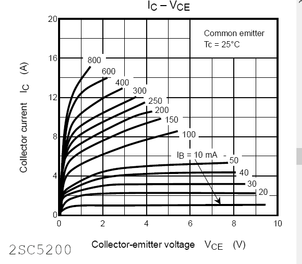
Making your R1 2000 ohms from 1000 ohms improves the output with slightly less output power. What do you expect for output power and what do you have for input voltage?
Also the transistors are large current perhaps some thing smaller? The circuit you are using has a base current of about 1.8 ma for the 2SC5200 at 150 mv peak input that is quite low.
-
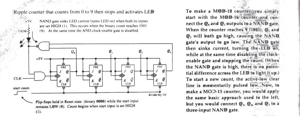
The circuit below is similar to what you want to do. Using a 4 input NAND gate you can connect it to the 4 outputs that represent the valve you want. Your NAND gate output would connect to the clr line.
-
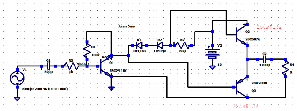
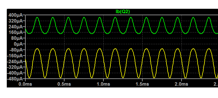
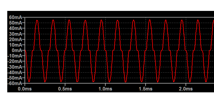
The output looks good in the simulator at 120mv(peak to peak) the current through the 8 ohm resistor is about 500ma pp which is about 1 watt. At 150mv the output is starting to clip on the bottom. This is do to the PNP Q3 having more base current than Q2. Q3 is directly connected to Q1 while Q2 is off from Q1 by the two diodes or 2 * 0.7 volts I would think. The base currents; green is Q3 and yellow is Q2.
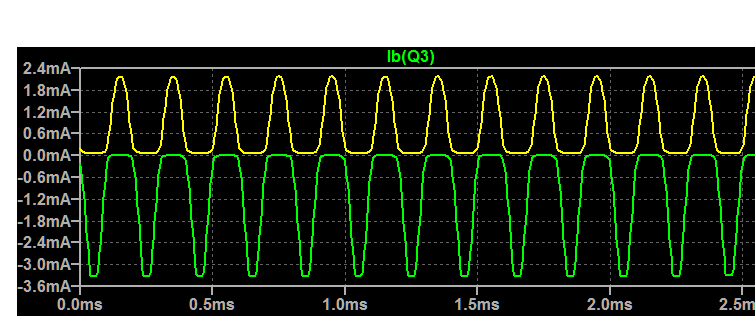
I like this circuit better as it is symmetrical; both transistor get the same amount of base current I would think.
-
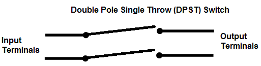
So you have a double pole single throw switch. There are two sets of contacts in the switch. Two of the connectors connects to one set of contacts and the other pair of connectors connect to the other set of contacts. You need to know which pair of connectors connects to each set of contacts. I believe.
-
Do you have a number/ID for the 4 pole switch?
-
Using what I could find for similar transistors in the simulator I used your circuit:
Green trace is the current through the NPN and yellow the PNP. The current through the 8 ohm load looks good inspite of the asymmetry in the transistor currents.
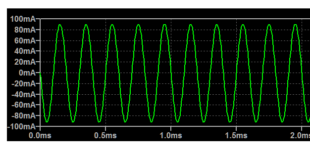
Connecting the PNP between the two diodes removes the asymmetry but changes the output current:
-
What are you connecting it to? Perhaps the impedance is to low?
-
see "Simple Way to Fix Out of sync stepper motors" at:
-
On 7/6/2021 at 5:21 PM, Engr. Philip said:
Which site can I buy good quality electronic components at cheap price and with free shipping
Good quality and cheap price do not go together. I buy cheap from Ebay but not always good. I buy some from Amazon.com because I have prime and can get things quickly. Jameco.com is a good hobbies supplier but they are on the west coast and I am on the east so delivery is slow; also digikey.com is high quality but to slow for me.
-
I believe what you are looking for is an Automatic Transfer Switch. see:
https://en.wikipedia.org/wiki/Transfer_switch
-
The 5 relays on the board are single pole - single throw. You wish to expand the number of contacts with you switch? What type are the switches? You mention schematics? Where does the latching come in?
-
Looks like you will have will have to draw it out yourself. If you have photoshop or The GIMP you can use the photographs and lay one (as a transparent layer) over the other; that helps. Else buy a new one:
https://www.ebay.com/itm/283527434087?hash=item42038d4f67:g:unQAAOSwh4ZfImWk
-
I lost my modem so I am down until this weekend or Monday. I will help answer questions then. I am using the library's wi-fi today.
-
I wonder if you could gleam some useful information from this article; it's for the CS5464.
https://corgitronics.com/2014/06/30/using-the-cirrus-logic-cs5464-for-ac-current-measurement/
-
Try https://github.com/stamp/CS5484.git
At on clicking the [code} button see download ZIP
I see I am now Rank: Newbie(1/14). Does that mean all my past sins have been forgotten?
-
There is a library file ( GOLANG library for SPI ) here that maybe helpful?
https://github.com/stamp/CS5484
I have problems finding the page that has the {code} button to download the file; you may have to dork around with the URL a bit.
-
- There are a number of sellers on Ebay that have 4 channel modules that ship from China. Most have relay outputs or other types of outputs. Not knowing where in the world you are makes it difficult to help you. The RS-485 is also known as the EIA-TIA 485 or TIA-485. See for example:
- https://www.ebay.com/itm/164863960516?
-
How does one edit their Public Profile? I can see it under Profile but not how to change it.
-
My Razor Ecosmart scooter uses a 500 watt motor and the Gyroor Warrior off terrain hover board uses a pair of 350 watt motors for a total of 700 watts. 750 watts equals 1 horsepower. see:
-
- You may find some useful information on Wikipedia here: https://en.wikipedia.org/wiki/Voltage-controlled_oscillator
I believe it is a trade off between the noise created by high frequency VCOs and that introduced by the multipliers. A low frequency VCO has less noise so using a multiplier to get the high frequency gives the best overall performance. But I can not find the literature that discusses that.
-
You do not give enough information to enable one to be very helpful to you. What are your requirements for you off road rover? You may look at similar devices (like electric scooters perhaps) via the internet and see what size motors they use.
Here are some 12 volt motors from 1hp to 1/3 hp. https://www.ebay.com/itm/233312841977?_ if that link does not work search on ebay for "DC MOTOR, 1/3~3HP, 56C, 12/24/90/180V, 1750RPM, TEFC, Permanent Magnet"
-
You can use one series resistor. See "Calculating an LED resistor value" at https://www.electronicsclub.info/leds.htm
resistor =(supply voltage - LED voltage)/LED current = (62 - 2)/0.020 = 3000 ohms which is a standard resistor value.
-
It depends on the area of specialization. See Penn State ( Pennsylvania, USA) for example.
https://www.eecs.psu.edu/students/undergraduate/EECS-Students-Undergrad-EE-Specialization.aspx
-
On 6/9/2021 at 10:47 AM, torpid whale said:
My batter is this one. and I have the correct PD charger. and my boost converter is capable of supporting the needed current.
Can you provide a block diagram of your set up? You speak of "my boost converter" isn't the ZY12PDN a type of boost converter? From the USB_C five volts to various voltages?
Some useful data here: https://www.alexwhittemore.com/notes-on-usb-pd-triggers-and-zy12pdn-instructions/


Advice Please On this amp design
in Electronic Projects Design/Ideas
Posted
This works well in the simulator using the transistors shown: