
Ashish Adhikari
-
Posts
43 -
Joined
-
Last visited
-
Days Won
2


Ashish Adhikari's Achievements
")


-
 A water level indicator detects and indicates the level of water in an overhead tank and relays the information back to a control panel to indicate whether the tank has a high or low water level. In this tutorial, I am going to use the ULN2003 IC to create a simple, inexpensive water level indicator. Using this circuit you can easily control the wastage of water and electricity. Watch this video, for detailed step by step instructions on how to build this circuit and to know how this circuit works. Towards the end of the video I will also discuss whether its really worth building this circuit. Components Required For this tutorial we need: 1 x ULN2003 IC 8 x Different Color LEDs 8 x 1K Resistors 1 x 220Ohm Resistor 1 x Buzzer A Long Ribbon Cable, and A Breadboard or a Custom Built PCB About The ULN2003 IC The notch on the top indicates the starting and stopping points of the numberings of the chip. Starting from left to right going counterclockwise this is the Pin number 1 of the IC. On the left hand side Pin 1 to 7 are the Base Inputs. On the right hand side Pin 10 to 16 are the Collector Outputs. Pin 9 is the Common Cathode node for flyback diodes (required for inductive loads). And, Pin 8 is the Common Emitter shared by all channels of the IC. This pin is typically tied to ground. The UNL2003 IC contains 7 High Voltage, High Current NPN Darlington Transistor Arrays each rated at 50V, 500mA in a 16-pin DIP package. You can connect the IC directly to a digital logic (like Arduino or Raspberry Pi, TTL or 5V CMOS device) without an external dropping resistor. The ULN2003 is known for its high current and high voltage capacity. The Darlington pairs can be "paralleled" for higher current Output. To know more about this IC, please check out my "Tutorial No. 51: All About ULN2003 IC", the link is in the description below. Circuit Diagram The circuit is very simple. I have connected 7 LEDs to the 7 OUT Pins of the IC via 1K Resistors. On my left, are the 7 digital inputs which are connected to a ribbon cable. The other end of the ribbon is submerged in the water tank with exposed terminals at various heights to detect the water levels. Along with the 7 wires, there is an eighth wire that stays at the bottom of the tank and is connected to the +ve terminal. As the tank starts filling up, the water level rises and a conductive path is created between the positive terminal and the base of Darlington Transistor inside the IC. Hence a logic HIGH is sent to the Input Pin of the IC which leads to the corresponding OUT Pin to go LOW lighting up the LEDs one by one starting from the bottom Red to the top Green. The bottom Red LED indicates lack of water and the top Green LED indicates that the tank is 100% full. You can also add a buzzer to the circuit to get an audio indication when the tank is full. If you want to be super funky, you can also add a relay module which can turn on and off the water pump. Breadboard Demo Before assembling the components on a PCB, lets do a quick test on a breadboard to make sure our logic works as expected. For this demo, I am going to fill up a coffee mug with normal tap water. As you can see, the LED indicators go up from bottom Red to the top Green as I keep filling the mug. The buzzer starts buzzing when the mug is 100% full. Hence, our setup is working as expected. The Board So, this is how my board looks like in 2D and 3D. If you want to learn how to design a PCB, please check out my "Tutorial No. 45: Transformers PCB BADGE", the link is in the description below. Component Assembly Now, lets solder the components to the board. Lets first solder all the resistances to the board. Then, lets solder all the LEDs to the board. I am using a 3mm Green LED as the power indicator. Next, I am soldering the IC base to the board. Since I care a lot about my ICs and micro-controllers, I never solder them directly to the board. In case of an ICs, I always try to use an IC bases or if a base is not available I use female pin headers. After soldering the IC base, I am soldering the Buzzer to the board. Now to conclude the setup, I am soldering the Ribbon Cable to the board. For my setup, I am only using half a meter long cable. But in a real-world scenario, you will definitely need a cable longer than this. Final Demo So, this is how the final setup looks like. As the water level rises, a conductive path is created between the positive terminal and the base of Darlington Transistors inside the IC. This triggers a logic HIGH at the Input Pins of the IC and the corresponding OUT Pins goes LOW lighting up the LEDs one by one starting from the bottom Red to the top Green. When the mug is 100% full the top green LED lights up and we also hear a noises of the buzzer. Usability To be very frank, I see more disadvantages than advantages of using this IC in building a liquid level indicator. You may have a different opinion, but my opinion is based on the below facts: The choice of the probes that will remain submerged in the liquid has to be done very carefully as they: Rust, foul and deteriorate due to "corrosion" and "electrolysis" causing the LEDs to slowly fade and finally turn off. Hence the probes need to be cleaned and replaced every 2 - 3 years. This circuit will work well with tap water, however do not use this with salt water or with any flammable liquid. If in your house you get hard-water, there will be salt deposits on the probes and you will have to clean the salt deposits on a regular basis. This circuit will not work if you have a metal tank. Replacing the contact points with something "non-corrosive" may help but I will not put my bet on that. Another option is to have "large electrodes" which will have a low impedance even when covered with impurities. To conclude I would like to say that the ULN2003 is not the best device to use for this application. You might be better using a "CMOS buffer" or inverter which needs less water conductivity to operate and also gives a more sudden output change as the input voltage rises and falls, along with "non-corrosive large electrodes". Thanks Thanks again for checking my post. I hope it helps you. If you want to support me subscribe to my YouTube Channel: https://www.youtube.com/user/tarantula3 Video: View Full Blog Post: View References GitHub: View Gerber: View DataSheet: Download All About ULN2003 IC: View Transformers PCB BADGE: View DIY Relay Module: View Support My Work BTC: 1Hrr83W2zu2hmDcmYqZMhgPQ71oLj5b7v5 LTC: LPh69qxUqaHKYuFPJVJsNQjpBHWK7hZ9TZ DOGE: DEU2Wz3TK95119HMNZv2kpU7PkWbGNs9K3 ETH: 0xD64fb51C74E0206cB6702aB922C765c68B97dCD4 BAT: 0x9D9E77cA360b53cD89cc01dC37A5314C0113FFc3 LBC: bZ8ANEJFsd2MNFfpoxBhtFNPboh7PmD7M2 COS: bnb136ns6lfw4zs5hg4n85vdthaad7hq5m4gtkgf23 Memo: 572187879 BNB: 0xD64fb51C74E0206cB6702aB922C765c68B97dCD4 MATIC: 0xD64fb51C74E0206cB6702aB922C765c68B97dCD4 Thanks, ca gain in my next tutorial.
 -
The UNL2003 IC contains 7 High Voltage, High Current NPN Darlington Transistor Arrays each rated at 50V, 500mA in a 16-pin DIP package. You can connect the IC directly to a digital logic (like Arduino or Raspberry Pi, TTL or 5V CMOS device) without an external dropping resistor. This IC features "common-cathode flyback diodes" for switching inductive loads. The ULN2003 is known for its high current and high voltage capacity. The Darlington pairs can be "paralleled" for higher current Output. The inputs are capable with TTL and 5v CMOS logic. Now, let's deep-dive and check out the internals of the IC and how it can be used in our projects. Pin Configuration and Functions The notch on the top indicates the starting and stopping points of the numberings of the chip. Starting from left to right going counterclockwise this is the Pin number 1 of the IC. * On the left hand side Pin 1 to 7 are the Base Inputs. * On the right hand side Pin 10 to 16 are the Collector Outputs. * Pin 9 is the Common Cathode node for flyback diodes (required for inductive loads). * And, Pin 8 is the Common Emitter shared by all channels of the IC. This pin is typically tied to ground. Detailed Description Inside the IC is the arrays of the 7 NPN "Darlington Transistors". Darlington Transistors were first invented in 1953 by Sidney Darlington. A Darlington pair is a circuit consisting of two Bipolar Transistors with the Emitter of one transistor connected to the Base of the other transistor. In this setup, the current amplified by the first transistor is further amplified by the second transistor. The collectors of both transistors are connected together. This configuration has a much higher current gain than each transistor taken separately. A small base current can make the pair switch to a much higher current. It appears as if it is just a single transistor, with only one base, one collector, and one emitter. Creating a high current gain approximately to the product of the gains of the two transistors: β Darlington = (β 1 * β 2) + β 1 + β 2 Since, β1 and β2 are high enough, we can write the above statement as: β Darlington ≈ β 1 * β 2 This connection creates the effect of a single transistor with a very high-current gain. The 7 outputs are all "Open Collector". By Open Collector, we mean a collector that is not attached to anything. It's just open. In order for an open collector output device to work, the open collector has to receive sufficient power. In order for an NPN transistor to work, the collector and the base both need to receive sufficient power. The base turns the transistor on, and then a much greater current flows from collector to emitter, but only if the collector has sufficient positive voltage. So if you want to connect a load to the Output of the chip with an open-collector-output, you must attach the load to a positive voltage source that is sufficient enough to drive the load. Hence, the +ve side of the load connects to the +ve voltage rail and the -ve side connects to the OUTPUT pin of the IC. Hence, when the Base current goes HIGH, the current flows from the collector to emitter and the Output logic goes LOW turning ON the LED (load) connected to the OUT pin of the IC and vice-versa. The maximum Output Current of a single OUTPUT pin is 500mA and the total emitter-terminal current is 2.5A as per the datasheet. Now, let's have a closer look at a single Darlington pair (internal circuit diagram) of the ULN2003 IC. The GPIO input voltage is converted to base current through a series base 2.7kΩ resistor connected between the Input and Base of the Darlington NPN junction. This allows the IC to connect directly to a digital logic (like Arduino, Raspberry Pi, TTL or 5V CMOS device) without the need of external dropping resistors operating at supply voltages of 5V or 3.3V. The 7.2kΩ and the 3kΩ resistors connected between the Base and the Emitter of each respective NPN transistor acts as pulldown resistors preventing floating states and suppressing the amount of leakage that may occur from the input. To maximize the effectiveness, these units contain "Suppression Diodes" for inductive loads. The diode connected between the OUT pin and the COM pin (PIN 9) is used to suppress the "kick-back voltage" from an inductive load which is generated when the NPN drivers are turned off and the stored energy of the coils causes a reverse flow of current. A reverse biased suppressing diode is also placed between the Base-Emitter and the Collector-Emitter pair to avoid the Parasitic nature of the NPN transistors. Pin 8 is connected to the GND. Device Functional Modes Inductive Load In case of an inductive load, when the COM pin is tied to a coil, the IC is able to drive inductive loads and suppress the kick-back voltage through the internal free-wheeling diodes. Resistive Load When driving a resistive load, a pullup resistor is needed in order for the IC to sink current and maintain a logic HIGH level. In this case the COM pin can be left floating (not connected). This device can operate over a wide temperature range between –40°C to 105°C. Applications Now, lets hook this IC to a circuit. As we know, the ULN2003 IC can easily drive a high-current or high-voltage (or both) device, which a Microcontroller or a Logic Device cannot tolerate. Hence, they are widely used in driving inductive loads like motors, solenoids and relays. 1. In my first example, I am going to light up a few LEDs using this IC I have connected 7 LEDs to the 7 OUT Pins of the IC via 220Ohm resistors. On my left, are the 7 digital inputs directly interfaced to either a Microcontroller or a TTL Digital Logic. When a logic HIGH is sent to the input pin the corresponding OUT pin goes LOW lighting up the LED. 2. In my second example, I am driving a Unipolar Stepper Motor using this IC In this setup, I am using Pin 1~4 for INPUT and Pin 13~16 for OUTPUT. Each OUT pin is rated at 500mA. Pin 9 has the spike suppressor diode, and is connected to the +ve terminal. By sending combinations of 0's and 1's to the 4 input pins we can rotate our stepper motor. I have used this setup in my award winning Video Tutorial: "NodeMCU Based - 3D Printed Indoor Gauge Thermometer" the link is in the description below. 3. In my third example, I am going to light-up a few AC Lightbulbs using this IC For high voltage applications, we can use RELAYS to control motors, heaters, lamps or AC circuits which themselves can draw a lot more electrical voltage/current and therefore power. We can hook up a maximum of 7 Relays to this IC. In my setup, I have connected 4 Relays to the 4 OUT pins of the IC. An AC Lightbulb is connected to the NO-pin of the relay. When we send a Digital HIGH to the INPUT pin the corresponding OUT pin goes LOW and current flows through the coil pulling the armature, completing the circuit and hence lighting up the 220V Light Bulb. Same as the previous setup, Pin 9 with the suppressor diode is tied back to the +ve terminal. 4. In my 4th example, I am going to show you guys how to obtain more than 500mA at the OUTPUT As we know that each of the OUT Pins are rated at 500mA, then how can I drive a 1Amp device? All we have to do is, tie 3 of the OUTPUT pins on the OUT side, and tie 3 of the corresponding INPUT Pins on the INPUT side. Now the 3 INPUT pins act like a single INPUT Pin. So basically, we can parallel the inputs to get a higher amplified value of paralleled output. You may ask, why did I combine 3 INPUTS and OUTPUTS and not just 2? As per the datasheet each pin is rated at 500mA but the total output is 2.5A (*** Page 4 of datasheet ****). Hence, 2.5A / 7 Pins = 0.36 Approx. So, 0.36 * 3 = 1.07Amp Approx. which is what we want. Areas of Application The ULN2003A produced by Texas Instruments can be used for: 1. Driving motors and solenoids 2. Can be used as a Relay Driver for high voltage application (7 relays at the max) 3. To drive high current loads using Digital Circuits 4. To drive high current LED's 5. To create a water level indicator circuit 6. As a LED and Gas Discharge Display Drivers 7. Can also be used as a logic buffer in digital circuits and more... For more information about the packaging and the material used, please have a look at the datasheet. The link is in the description below. Always consult a manufacturer's datasheet before assuming industrial conventions, no matter how intuitive or obvious they may be. "In the face of ambiguity, refuse the temptation to guess." - Zen of Python Thanks Thanks again for checking my post. I hope it helps you. If you want to support me subscribe to my YouTube Channel: https://www.youtube.com/user/tarantula3 Video: Watch Full Blog Post: Visit References DataSheet: Download Darlington transistor: View Open Collector Output: View Transistor–Transistor Logic: View Parasitic Structure: View Related Videos NodeMCU Based - 3D Printed Indoor Gauge Thermometer: View Acronyms TTL: Transistor–Transistor Logic CMOS: Complementary Metal–Oxide–Semiconductor Support My Work BTC: 1Hrr83W2zu2hmDcmYqZMhgPQ71oLj5b7v5 LTC: LPh69qxUqaHKYuFPJVJsNQjpBHWK7hZ9TZ DOGE: DEU2Wz3TK95119HMNZv2kpU7PkWbGNs9K3 ETH: 0xD64fb51C74E0206cB6702aB922C765c68B97dCD4 BAT: 0x9D9E77cA360b53cD89cc01dC37A5314C0113FFc3 LBC: bZ8ANEJFsd2MNFfpoxBhtFNPboh7PmD7M2 COS: bnb136ns6lfw4zs5hg4n85vdthaad7hq5m4gtkgf23 Memo: 572187879 BNB: 0xD64fb51C74E0206cB6702aB922C765c68B97dCD4 MATIC: 0xD64fb51C74E0206cB6702aB922C765c68B97dCD4 Thanks, ca again in my next tutorial.
-
Had some time this weekend and a desire to create something new and interesting, so went ahead and created an Arduino/NodeMCU based indoor dial thermometer. This device displays the temperature in degree centigrade on a D-Shaped Gauge as well as on a 7-Segment display. In addition to that, it also saves the temperature and humidity readings in a MySQL DataBase hosted on a home based Raspberry Pi Server. The data is then displayed using the "Our Smart Home" app. Awards This project got featured on Cults3D and Instructables https://cults3d.com/en/3d-model/gadget/arduino-based-indoor-dial-thermometer https://www.instructables.com/NodeMCU-Based-3D-Printed-Indoor-Gauge-Thermometer/ Components Required For this project we need: 2 x TM1637 Display Modules 1 x DHT22 or DHT11 Module 1 x NodeMCU Microcontroller 1 x 28BYJ-48 Stepper Motor with ULN2003 Driver Board 1 x 10K Resistor A 3D Printer Copper Wire and Some Nuts & Bolts Circuit Diagram The circuit is very simple. Connect the ULN2003 driver board’s IN1, IN2, IN3 and IN4 to the NodeMCUs digital pins D0, D1, D2 and D3. Then connect the OUT Pin of the DHT22 to the D5 Pin of NodeMCU. After that connect the 2 x Display Modules to the microcontroller. We are going to use a Common Clock Pin D4 for both modules. Then connect the DIO of one of the modules to D6 (TEMP) and the other one to D7 (HUM) pins on the NodeMCU. Important: Please avoid using the boot config pins D3, D4, D8 and the RTC pin D0 for the displays. Now, on the D8 Pin we are going to connect the switch. This switch has a very important role in this circuit. This switch acts as the 'home' or the 'starting point' of the stepper motor. When the switch is open Pin D8 is connected to GND through the pull-down resistor and we read a LOW. When the switch is closed, Pin D8 connects to 3.3v pin of NodeMCU and we read a HIGH. When the 'temperature changes' or the 'device boots up', the pointer starts moving 'counterclockwise'. As soon as the pointer hits the home position, Pin D8 reads HIGH and the logic moves the pointer 'clockwise' to display the temperature on the gauge as read by the DHT22 module. The Code The code starts by including all the necessary libraries. Then it defines all the variables needed for setting up the WiFi connection. Next, it assigns a static IP address to the ESP8266 (if you want to use DHCP then go ahead and delete these three lines from the code). After that, it sets up the 2 x URLs that are needed for updating the heartbeat, temperature and humidity. String URLUpdateStatus = "http://192.168.0.7/Arduino/Weather/UpdateStatus.php"; String URLUpdateTemp = "http://192.168.0.7/Arduino/Weather/UpdateTemperature.php"; Before going ahead let's have a quick look at the 2 php files. The "UpdateStutus.php" file uses an UPDATE query to update the timestamp of the device sending the request to the current epoch time and hence updating the heartbeat. <?PHP try { $Token = $_GET["Token"]; $Location = $_GET["Location"]; include "ConnectionStringArduino.php"; // Create connection $sql = 'Update `Status` SET `DateTime`=\''.time().'\',`State`=\'1\' WHERE `Device`=\''.$Location.'\' AND `Token` = \''.$Token.'\';'; $result = $con->query( $sql ); if($result === FALSE) { die(mysqli_error());} mysqli_close($con); } catch (Exception $e) {} ?> The "UpdateTemperature.php" uses an INSERT query to add a new row to the database with the current values of Temperature and Humidity. <?PHP try { $Location = $_GET["Location"]; $TEMP = $_GET["TEMP"]; $HUM = $_GET["HUM"]; include "ConnectionStringArduino.php"; // Create connection $sql = "INSERT INTO `Weather` (`DateTime`,`Temperature`,`Humidity`,`Location`) VALUES ('".time()."','".$TEMP."','".$HUM."','".$Location."');"; $result = $con->query( $sql ); if($result === FALSE) { die(mysqli_error());} mysqli_close($con); } catch (Exception $e) {} ?> This is what is written to the database and can be displayed using Google Charts, in my case, I am using the "Our Smart Home" app to display the data using php and JavaScript. Currently I am only displaying the data from the Study room and the Peg Box. To know more about my award winning "Peg Box" project please have a look at my electronics tutorial no. 34 "Peg Box with Temperature and Humidity Monitor using NodeMCU" (https://youtu.be/elH331NXPsU). After that, I am defining all the variables required for reading and storing the value of temperature and humidity. Next, I am defining all the variables and setting up any additional symbols required for displaying temperature and humidity on the TM1637 Display Module. After that, I am defining the D8 pin of the NodeMCU as the reset switch pin. We will talk about this in detail in the following sections. Next, I am setting up the Steps Per Revolution of the stepper motor as 2038 and then initializing the stepper library through pins D0 to D3. const int stepsPerRevolution = 2038; // Change this to fit the number of steps per revolution of your motor Stepper myStepper(stepsPerRevolution, D0, D2, D1, D3);// Initialize the stepper library on pins D0 through D3 One thing to note: since I need both clockwise and counterclockwise movements, I have to initialize the pins in the order shown on screen. Then in the setup() section, first I am setting up the WiFi connection and then sending a heartbeat to the server. Then I am setting up the brightness of the 7-Segments to their max values followed by starting the dht module and finally setting the pin-mode of the switch to INPUT. void setup() { Serial.begin(115200); // Initialize the serial port /*********** Setup a WiFi connection ***********/ if (WiFi.config(local_IP, gateway, subnet)) { Serial.println("Static IP Configured"); } else { Serial.println("Static IP Configuration Failed"); }; WiFi.mode(WIFI_STA); WiFi.begin(WIFI_SSID, WIFI_PWD); while (WiFi.status() != WL_CONNECTED) { delay(500); Serial.print("."); }; Serial.println("\nWiFi connected"); Serial.print("IP address: "); Serial.println(WiFi.localIP()); SendIamAlive(); // Send the initial wakeup message to the server /**********************************************/ display_TMP.setBrightness(7); // Set the display brightness (0-7) display_HUM.setBrightness(7); // Set the display brightness (0-7) dht.begin(); // Setup the DHT sensor pinMode(SWITCH, INPUT); // Declare the switch pin as input }; Now, in the loop() section I am reading the temperature using the Read_Temp() function and then sending the Temperature and Humidity values every 30 minutes and heartbeat every minute to the home server. void loop() { /** Read the temp and humidity info from ther sensor and display it on the 7-segmnet and Gauge **/ Read_Temp(); /** Sending Humidity and temperature every 30 minutes **/ if((millis() - lastTime) > timerDelay){ Serial.println("Sending Temp and Humidity");SendTemperatureAndHumidity(); lastTime = millis(); }; /** Sending I am alive message every minute **/ if((millis() - StatusCounter) > 60000){ Serial.println("Sending Heartbeat"); SendIamAlive(); StatusCounter = millis(); }; }; Next, you see the definition of the SendIamAlive() and SendTemperatureAndHumidity() functions which utilizes the WiFiConnect() function to send the values using the previously discussed URLs. The Read_Temp() function reads the temperature and humidity and updates the 7-Segment displays and moves the pointer only if there is a change in the values. The Move_Needle() function first sends the pointer to the home position using the Return_Home() function and then looks through and moves the pointer to the correct position until the stepCout is = STEPS. The value of STEPS is calculated based on the "stepsPerRevolution" which we previously set it up as 2038. So, 2038 / 2 (for half circle) = 1019 Now by dividing 1019 by 180 degrees we get the steps required to display each degree centigrade. Now to display each degree centigrade we need 180/60 = 3 divisions. Since our gauge starts from -10 and not 0 we also have to add the first 10 blocks which is (5.661 * 10 * 3) to our calculation. int STEPS = (5.661 * 3 * TEMP) + 169.833; // 5.661 (step resolution) * 3 (steps to display each °C) * TEMP + 169.833 (5.661 * 10 * 3) = since it starts from -10 and not 0) That's it as easy as that. 3D Designing Lets have a quick look at the 3D model of the project. At the front, we have The Pointer, D-Shaped Dial, and the Temperature Scale on the dial. Down at the bottom we have the Enclosure that will house the microcontroller and all other electronics components in it. The enclosure has a Lid to keep the electronic components safe and sound. At the back, we have a pocket to hold the DHT22 Module, 3 x holes for the stepper motor, 2 x groves for the TM1637 Display Module and 2 x L-Shaped Brackets to hold the top Dial to the bottom Enclosure. 3D Printing Once the 3D models were sorted, it was time for me to fire up my 3D printing oven and start printing these 3D models. I used: - 1.75mm Cold White PLA Filament, and printed the models with - 0.2mm - with 0% infill - and with support. As we all know, 3D printing is the process that uses computer-aided design or CAD, to create objects layer by layer. 3D printing is not a new technology, it's been there since the 1980's, when Charles W. Hull invented the process and created the first 3D-printed part. Since then, the field of 3D printing has grown exponentially and holds countless possibilities. The 3D printing process fascinates me a lot and I sometimes love to sit near my printer and watch these layers getting printed. The entire printing process took a little over 5 hours to complete and this is the final result. Alright now, let's start gluing all the printed parts. I first superglued the L-Shaped Brackets to the dial followed by the pocket that will hold the DHT22 module. Then, I went ahead and screwed the bottom enclosure to the top section via the L-Shaped Brackets. Breadboard Demo Before adding the electronic bits to the 3D printed bits, let's do a quick test to make sure everything works as expected. So, this 7-Segment display is displaying the temperature and the other one is displaying the humidity. The needle is currently going round and round in circles as it has no idea where to stop. To stop the needle, and to send it the correct position on the gauge, I need to connect this red jumper cable connected to 3.3v to the D8 Pin of the NodeMCU. Once I short the cable, the needle changes its direction and moves clockwise to display the temperature value read from the DHT22 module. The temperature and humidity values are also sent to the 'Home Server' which are then displayed using the "Our Smart Home" app. Coloring Using Acrylic colors, I painted all the 3D printed parts of the project. Assembling Once the coloring is done, its now time for me to put all the electronic components together. First I screwed the stepper motor to the back of the dial. Then, I gently pushed the DHT22 Module into its pocket at the back of the dial. Now the interesting bit. As per our previous discussion, we are going to use a copper wire as a switch that will move the pointer to its correct position. The copper wire will be fed through these two holes from the back and will loop through this small pipe like structure in the front. A small cut will be made on the top exposed side of the copper wire. Now on the pointer, we need to add a small piece of copper wire. When this copper bit touches the two copper wires on the pipe, it will complete the circuit and will send a HIGH to the system. Next, I am hot gluing the two TM1637 7-Segment Display Modules to the back of the dial. Once done, it's pretty much just a matter of soldering all the sensors to the NodeMCU as per our circuit diagram. Final Demo So, this is how my final setup looks like. Once the device is turned on, the pointer moves counterclockwise until it touches the copper wires that acts like a switch. Upon touching the wires the pointer moves clockwise to display the temperature value read from the DHT22 module on the D-Shaped Gauge. The temperature and humidity values are also displayed using 7-Segment Displays. The values are also sent over WiFi to a Raspberry Pi Home Server and stored in a MySQL database. Using google charts, you can display the data using various different graph options. In my case, I am using the "Our Smart Home" app to display the data using php and JavaScript. Thanks for watching, please comment and let me know if there are any scopes of improvement. Thanks Thanks again for checking my post. I hope it helps you. If you want to support me subscribe to my YouTube Channel: https://www.youtube.com/user/tarantula3 Video: Watch Full Blog Post: Visit Thermometer STLs: Download Peg Box: Watch How To Wire A Pushbutton: View Stepper Motor Specs: View Support My Work BTC: 1Hrr83W2zu2hmDcmYqZMhgPQ71oLj5b7v5 LTC: LPh69qxUqaHKYuFPJVJsNQjpBHWK7hZ9TZ DOGE: DEU2Wz3TK95119HMNZv2kpU7PkWbGNs9K3 ETH: 0xD64fb51C74E0206cB6702aB922C765c68B97dCD4 BAT: 0x9D9E77cA360b53cD89cc01dC37A5314C0113FFc3 LBC: bZ8ANEJFsd2MNFfpoxBhtFNPboh7PmD7M2 COS: bnb136ns6lfw4zs5hg4n85vdthaad7hq5m4gtkgf23 Memo: 572187879 BNB: 0xD64fb51C74E0206cB6702aB922C765c68B97dCD4 MATIC: 0xD64fb51C74E0206cB6702aB922C765c68B97dCD4 Thanks, ca gain in my next tutorial.
-
A Gothic Lantern is a captivating piece of lighting that brings the allure of the Victorian Era into your home. The lantern is adorned with ornate top and bottom ornaments, reminiscent of the Gothic style that was prevalent during the Victorian Era. My curiosity to create something new and interesting got me into this gothic style rechargeable lantern. The design is both nostalgic and timeless, making the Gothic Lantern a perfect fit for homes that cherish a touch of historical charm. Watch this video for detailed step by step instructions on how to build this lantern and for a complete instruction on how the electronic circuit works inside the lantern. Downloading The STL Files I went online and searched for a "Gothic Lantern" and found a very popular design by Shira. The STL files were free to download from "Cults3D.com". It was literally a hard to resist 3D model. So, I went ahead and downloaded the lantern's STL files for my project. Modifying The STL Files The downloaded STL files only comes with the top and the body of the lantern. However, my aim is to add some electronics to the design to turn it into a rechargeable lantern. To achieve this, I created few more 3D models and added them to the design. I created a base that can hold an "18650 battery holder" and an "USB Type-A charging cable". I also created a "LED holder" that will go inside the body of the lantern. The LED holder has 10 x 5mm holes to hold the 10 white LEDs in it. It will also house the "TP4056 18650 Lithium battery charging module". I also created a "ring" that will go on top of the lantern. Holding this ring, you can go anywhere with this lantern. 3D printing Once the 3D models were sorted, it was time for me to fire up my 3D printing oven and start printing these 3D models. I used: - 1.75mm Cold White PLA Filament, and printed the models with - 0.2mm - with 0% infill - and with support. As we all know, 3D printing is the process that uses computer-aided design or CAD, to create objects layer by layer. 3D printing is not a new technology, its been there since 1980's, when Charles W. Hull invented the process and created the first 3D-printed part. Since then, the field of 3D printing has grown exponentially and holds countless possibilities. The 3D printing process fascinates me a lot and I sometimes love to sit near my printer and watch these layers getting printed. The entire printing process took a little over 53 hours and this was the final result. Circuit Diagram The circuit is very simple. A USB Type-A charging cable connects to the input of the TP4056 Module. The 18650 Battery connects to the B+ and B- terminals of the module. And finally, the LEDs connect parallelly to the OUT+ and OUT- terminals of the module with a push button switch connected to the +ve terminal. Using this switch we can turn on or off the lantern. Soldering Lets start by soldering the wires to the LEDs. As previously discussed, all these LEDs will be parallelly connected to each other. Next, I screwed the 18650 battery holder to the base of the lantern. After that, I superglued one of the LED holders to the base, and then one by one slided the LEDs into the holes of the LED holder. After that, I soldered the TP4056 module as per the circuit diagram. To conclude the setup, I pushed the remaining LEDs into the holes of the 2nd half of the LED holder and then superglued it to the base of the lantern. Coloring I wanted to give this lantern a "rustic wooden texture". For that I applied acrylic "Raw Sienna" and "Burnt Umber" to the body of the lantern. Final Assembly I wanted this lantern to have a soft illumination without any harsh light. So, I went ahead and used the white plastic of a milk bottle to give this lantern a defused lighting effect. I used metal pieces and magnets to stick the bottom plate to the base of the lantern. Once all the electronics bits were sorted, I screwed the body of the lantern to the base. Then to conclude the setup, I superglued the top to the body of the lantern, that's it all done. Demo So, this is how my final setup looks like. The red glow inside the lantern (bit hard to see in the bright sunlight), indicates that the battery is charging. Press the push button switch from the base of the lantern to turn it on or off. Do comment, and let me know if there are any scopes of improvement. Thanks Thanks again for checking my post. I hope it helps you. If you want to support me subscribe to my YouTube Channel: https://www.youtube.com/user/tarantula3 Video: Visit Full Blog Post: Visit Solar Battery Charger: Video Gothic Lantern STLs: Github Model inframe: Instagram Support My Work BTC: 1Hrr83W2zu2hmDcmYqZMhgPQ71oLj5b7v5 LTC: LPh69qxUqaHKYuFPJVJsNQjpBHWK7hZ9TZ DOGE: DEU2Wz3TK95119HMNZv2kpU7PkWbGNs9K3 ETH: 0xD64fb51C74E0206cB6702aB922C765c68B97dCD4 BAT: 0x9D9E77cA360b53cD89cc01dC37A5314C0113FFc3 LBC: bZ8ANEJFsd2MNFfpoxBhtFNPboh7PmD7M2 COS: bnb136ns6lfw4zs5hg4n85vdthaad7hq5m4gtkgf23 Memo: 572187879 BNB: 0xD64fb51C74E0206cB6702aB922C765c68B97dCD4 MATIC: 0xD64fb51C74E0206cB6702aB922C765c68B97dCD4 Thanks, ca gain in my next tutorial.
-
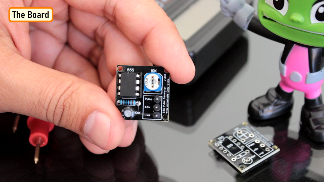
The 555 timer IC is an integrated circuit (IC) that is used in a variety of timer, delay, pulse generator and oscillator circuits. In this tutorial, I am going to show you guys how to make an "Adjustable Delay Timer Circuit" using the 555 timer IC. This circuit can automatically turn on/off any circuit after a fixed duration. This timer circuit is useful when you need to power On/Off any AC Appliances after a pre-defined duration. For example, you can use this circuit to automatically turn off a mobile charger after a certain period of time to avoid over charging, or you can turn on/off a light bulb after a certain period. The time delay of this circuit can be adjusted by using various combinations of resistors and capacitors. Watch this video for detailed step by step instructions on how to build this circuit and to know how this circuit works. Components Required For this tutorial we need: A 555 Timer IC A Push Button Switch A Red And A Green LED 2 x 220Ohm Current Limiting Resistors 1 x 10K Resistor A Breadboard and Few Breadboard Connectors A 5V Power Supply A 470uF Capacitor And Few Combinations Of Resistors Or A Potentiometer 555 Timer IC In Monostable Mode Lets start by putting all the components together and lets understand how the circuit works. In the first example, I am going to show you guys the "on-off timer circuit" with a fixed timing Resistor and Capacitor. The heart of this circuit is the 555 timer IC. Pin No.1 of the IC is connected to GND. By connecting Pin 6 and 7 of the 555 timer IC, we put the IC in "Monostable Mode". In Monostable Mode, the output of the IC is stable in "One State", and it will always return to this state after a certain period of time when it gets pushed out of that state. The output at Pin 3 of the 555 Timer IC in monostable mode is generally LOW - indicated by the green LED. When you trigger the circuit using the push button switch, the output goes HIGH - indicated by the red LED, for a certain period of time before it goes back to its LOW state. The time the circuit stays HIGH is decided by the value of a resistor R1 and a capacitor C1. The higher the values, the longer it stays HIGH (On). To adjust the timer duration "on-the-fly", the timing Resistor R1 can be replaced by a Potentiometer. By changing the value of the resistance of the potentiometer we can either increase or decrease the duration of the timer. Logic Using Circuit Simulation Alright, now I am going to explain how this circuit works with the help of an animation. When Pin 2 of the IC detects voltage LESS than 1/3rd of the supply voltage, it turns ON the output on Pin3. And, when Pin6 detects voltage MORE than 2/3rds of the supply voltage, it turns OFF the output. Whenever the output of the IC is in OFF state, the Discharge Pin (Pin7) acts as ground, as it is internally grounded. This is how the trigger pin (Pin2) and the threshold pin (Pin6) of the 555 timer IC sense voltages and controls the output at Pin3. When we power on the circuit, the output is in OFF state. Hence, the discharge pin (Pin7) will be internally grounded discharging the capacitor. Pressing the push button switch activates the delay timer and the following sequence starts: Trigger Pin (Pin2) gets grounded Since this applied voltage at Pin2 (0V) is less than 1/3rd of the supply voltage (5V), the output at Pin3 turns ON And at the same time, the Discharge Pin (Pin7) disconnects internally from 0V This causes the capacitor to charge via the resistor or potentiometer Now, the voltage across Pin6 starts increasing As soon as the capacitor charges to 2/3rds of the supply voltage, Pin6 turns OFF the output When the output turns OFF, Pin7 gets internally grounded discharging the capacitor. The above steps are repeated each time you push the push button switch. The time period for which the capacitor charges from 0V to 2/3rds of supply voltage is the "delay time". Calculations A discussed earlier, the time period for which the capacitor charges from 0V to 2/3rds of supply voltage is the "delay time". We can calculate this time using the formula: T = 1.1 * R * C Where T is the time period in seconds, R is the value of timing resistor in ohms and C is the value of the capacitor in Farad. In the previous example we used a 33K resistor and 470uF capacitor which gives us a delay period of: T = 1.1 * (33000) * (0.000470) = 17 seconds. The Board To make things easy, I designed a PCB for this setup. So, this is how my PCB looks like in 2D and 3D. You can either add a resistance or a potentiometer to the board to control the delay time. I have created 2 versions of this board: V1: Without A Relay Module V2: With A Relay Module Using the board with the relay module, you can control other DC Circuits or AC Appliances. For a quick reference, I added the delay period calculator on the board. Soldering Alright, now, lets solder the components to the board. In this setup, I am going to solder a potentiometer to the board and hence I will leave the resistor bit as is. So, lets start by soldering all the resistances to the board. Then, lets solder the LEDs to the board followed by the Push Button Switch. After that, lets solder the IC base and the capacitor to the board. As discussed earlier, instead of the resistor I am soldering a Potentiometer to the board. To finalize the setup, I am soldering few male pin headers to the board, that's it all done. The 2nd version of the board with the relay module looks like this. Demo For the demo purpose, I am going to use the board that has the relay module on it. Using this board, I can demo both the operation of the relay and the LEDs. Lets set the resistance of the potentiometer to a desired value and then lets do the quick math to see how long this circuit will stay on. Alright, now that we have all the values, lets start the timer on my mobile and press the push button switch both at the same time............. Bingo, mission accomplished. You can use the relay in either NC or NO state in your project. Uses This Delay Timer Circuit can be used as a: Timer for any robotics project Turning off mobile chargers to prevent overcharging Turning On/Off lights automatically after a set duration In Auto power On/Off circuits using Relays and more.. The possibilities are endless.. Thanks Thanks again for checking my post. I hope it helps you. If you want to support me subscribe to my YouTube Channel: https://www.youtube.com/user/tarantula3 PCBWay 6th Project Design Contest: https://www.pcbway.com/activity/6th-project-design-contest.html Video: Visit Full Blog Post: Visit DIY - Relay Module: Video Schema: Download Circuit: Download Gerber Files: GitHub Support My Work BTC: 1Hrr83W2zu2hmDcmYqZMhgPQ71oLj5b7v5 LTC: LPh69qxUqaHKYuFPJVJsNQjpBHWK7hZ9TZ DOGE: DEU2Wz3TK95119HMNZv2kpU7PkWbGNs9K3 ETH: 0xD64fb51C74E0206cB6702aB922C765c68B97dCD4 BAT: 0x9D9E77cA360b53cD89cc01dC37A5314C0113FFc3 LBC: bZ8ANEJFsd2MNFfpoxBhtFNPboh7PmD7M2 COS: bnb136ns6lfw4zs5hg4n85vdthaad7hq5m4gtkgf23 Memo: 572187879 BNB: 0xD64fb51C74E0206cB6702aB922C765c68B97dCD4 MATIC: 0xD64fb51C74E0206cB6702aB922C765c68B97dCD4 Thanks, ca gain in my next tutorial. Tags ---- on-off timer circuit, Adjustable Delay Timer Circuit, 555 Timer Project, Breadboard Demo, Monostable Mode, astable mode, bistable mode, one-shot circuit, Circuit Simulation, relay Module NC. relay Module NO, 555 Adjustable Delay On Off Timer Circuit, circuit diagram, 555 IC, adjustable on off relay module, delay timer, time delay relay, off delay timer, Odysee: https://odysee.com/@Arduino:7/555-Adjustable-Delay-On-Off-Timer-Circuit:2 Cos: https://cos.tv/videos/play/48667261956559872 Rumble: https://rumble.com/v3w7p5k-555-adjustable-delay-on-off-timer-circuit.html
-
A ton of feature PCBs to be offered
Ashish Adhikari replied to Jolin He's topic in Sell/Buy electronics - Job offer/requests
Nice -
When the full moon is shining and the wolves are howling, it's time for Halloween's spooky spectacle. The snickering grins of jack-o'-lanterns glow from lit porches. Kids skip down the block in spooky costumes, carrying bags full of candy and shouting "Trick or Treat!". The Nightmare Before Christmas is almost here... Do you see dead people??? Alright Enough of that, in this Spooktacular video I am going to create an Arduino based 3D printed Halloween Décor. It's super easy, fun and spooky.... 3D Printing 3D Printing is a highly addictive hobby! This is the very first time I am using my 3D printer to print something electronics related. The STL files used in this project are all downloaded from www.Thingiverse.com. I have uploaded a copy of all the 3D Objects to my GitHub repository, the link is in the description below. 3D printing has changed my life. There are so many things you can do using a 3D printer. From designing 3D Models to printing them using the 3D printer has now become my new hobby. I've been a "maker" since I was 10 years old, and have always constructed and made my own stuff. 3D printing for me is a blessing. I am totally lost in the 3D printing heaven. 3D printing has changed my electronics workshop life forever. Before when I used to order parts, I always used to wonder if the parts would fit into my projects resources... but after I got my 3D printer... it doesn't matter at all, because if it doesn't fit - I could design and print it myself. The 3D printer was definitely "The Missing Piece" from my electronics workshop. Schematic Diagram Now that we have all our 3D Models printed, lets have a look at the component assembly. The assembly is super simple. We just need to connect 4 Yellow LEDs to D2, D3, D4 and D5 pins of Arduino via 220ohm current limiting resistor. Then connect the white LED to Analogue Pin D10 of the Arduino via a current limiting resistor. That's it, as simple as that. The Code Now, lets have a look at the code that will drive the LEDs. Lets start by defining all the variables. Then in the setup section lets define all the pin modes. To flash the LEDs I chose 5 different Flashing patterns: 1. All LEDs Flash Very Fast For 10 Seconds 2. All LEDs Flash Slowly For 10 Seconds 3. 2 LEDs Turn On and 2 LEDs Turn Off for 10 seconds 4. LED Chaser Circuit for 10 seconds 5. One LED Randomly Turn On for 10 seconds The switch statement in the loop() section randomly picks up one of these patterns and runs it for 10 seconds. The white LED also fades in and out after every cycle. At the bottom of the code, I have defined all these 5 LED flashing patter in their respective functions. Demo on Breadboard After loading the code on an Arduino Nano this is how it looks like. The white LED will go inside the Ghost and the Yellow LEDs will go inside the Pumpkins. Humm, that looks promising, isn't it? Assembling Let's start by soldering the wires to the LEDs. Then lets solder the Arduino Nano to a perf-board and then solder all the resistors to the board. Next, lets soldered the LEDs to the D2, D3, D4, D5 and D10 pins of the Arduino via the current limiting resistors. That's all you have to do for the electronics bit. Now, let's hot glue the perf-board inside the coffin, followed by all the LEDs to a wooden block. Before putting the 3D printed components on the LEDs, let's do a quick test to verify everything works as expected. Look at that... Now, one by one lets hot glue the 3D printed components to the plank. To finalize the setup, I added a few dry grass leaves to hide the wirings. That's it all done. Final Demo So this is how my final setup looks like. Do comment and let me know if there are any scopes of improvement. Until then, Happy Halloween.... Thanks Thanks again for checking my post. I hope it helps you. If you want to support me subscribe to my YouTube Channel: https://www.youtube.com/user/tarantula3 Video: Visit Full Blog Post: Visit Code: Download Schema: Download STL Files: Coffin: Download RIP: Download Pumpkins: Download Pikachu: Download Ghost: Download Instructables: https://www.instructables.com/3D-Printed-Arduino-Halloween-Décor/ Support My Work BTC: 1Hrr83W2zu2hmDcmYqZMhgPQ71oLj5b7v5 LTC: LPh69qxUqaHKYuFPJVJsNQjpBHWK7hZ9TZ DOGE: DEU2Wz3TK95119HMNZv2kpU7PkWbGNs9K3 ETH: 0xD64fb51C74E0206cB6702aB922C765c68B97dCD4 BAT: 0x9D9E77cA360b53cD89cc01dC37A5314C0113FFc3 LBC: bZ8ANEJFsd2MNFfpoxBhtFNPboh7PmD7M2 COS: bnb136ns6lfw4zs5hg4n85vdthaad7hq5m4gtkgf23 Memo: 572187879 BNB: 0xD64fb51C74E0206cB6702aB922C765c68B97dCD4 MATIC: 0xD64fb51C74E0206cB6702aB922C765c68B97dCD4 Thanks, ca gain in my next tutorial.
-
Proximity sensing is a very common application in electronics. There are several ways to accomplish this. The most common way is by using a PIR sensor. PIR Sensor senses the change in ambient infrared radiation caused by warm bodies. I have already covered this in my Tutorial No. 5: "PIR Sensor Tutorial - With or Without Arduino". However, since PIR sensors detect movement from living objects, they can generate false alarms. These sensors are also inefficient in hot environments, as they rely on heat signatures. The other common methods of proximity sensing involve, using reflected ultrasonic or light beams. Using these sensors, the intruding object is detected by the reflected beam back to its source. The time delay between transmission and reception is measured to calculate the distance to the object. In this tutorial, we are going to look at another method of proximity sensing using "Microwaves" and "Doppler Effect". In my hand is an inexpensive RCWL-0516 Microwave Radar Motion Sensor. The RCWL-0516 microwave sensor detects "any movement" from "any object" and does not rely on heat, making it more reliable in hot environments. I am going to use this sensor to create a Geo-fence around my house to detect motion and get notifications. What is the Doppler effect? The RCWL-0516 module uses a “Doppler Radar” that makes use of the "Doppler Effect" to detect motion and trigger proximity alerts. So, before understand how the RCWL-0516 sensor works, let’s understand the Doppler Effect. The Doppler effect, is named after the Austrian physicist Christian Doppler, who described this phenomenon in 1842. He described the change in frequency observed by a stationary observer when the source of the frequency is moving. The sound's pitch is higher than the emitted frequency when the sound source approaches the observer as the sound waves are squeezed into shorter distance (bunched together), which can be heard as a higher pitch. The opposite happens when the object moves away from the observer, causing the sound waves to become lower in frequency and lower in pitch (spread out). As a result, the observer can hear a noticeable drop in the pitch as it passes. This holds true for all sorts of waves, such as water, light, radio, and sound. How Does The RCWL-0516 Works? Like the PIR Sensors, these sensors also detects only movements within their detection range. But instead of sniffing the blackbody radiation of a moving object, these sensors uses a “Microwave Doppler Radar” technique to detect a moving object. Doppler microwave detection devices transmit a continuous signal of low-energy microwave radiation at a target area and then analyze the reflected signal. The target’s velocity can be measured by analyzing how the target’s motion altered the frequency of the transmitted signal. Due to Dopplers effect, the frequency of reflected microwave signal is different from the transmitted signal when an object is moving towards or away from the sensor. When a car approaches a speed trap radar, the frequency of the returned signal is greater than the frequency of the transmitted signal, and when the car moves away, the frequency is lower. This is how a speed gun calculates the speed of the car. Technical Specifications The technical specifications of this sensor are listed below: Operating Voltage: 4-28V (typically 5V) Detection Distance: 5-7 Meters Maximum Current Drawn: ~ 2.7 mA Operating Frequency: ~ 3.18 GHz Transmission Power: 20 mW (typical)/30 mW (max) Signal length: ~ 2s Regulated Output: 3.3V, 100mA RCWL-0516 Module Pin outs The RCWL0516 module is a single breakout board with the following connections: 3V3 : it is the "output" from the onboard 3.3V regulator which can be used to power external circuits. Remember, this is not an input pin. This pin can provide up to 100mA of current. GND : is the ground pin. OUT : is the 3.3V TTL logic output. This pin goes HIGH for 2seconds when a motion is detected and goes LOW when no motion is detected. The output of this module is "analog" and can be connected to an analog input of a micro controller and sampled by an ADC. The output voltage is roughly proportional to the distance between the sensor and the object. VIN : provides power to the module. Connect this pin to an input voltage anywhere between 4 to 28V (however, 5V is commonly used). This module consumes less than 3mA of current so, you can easily power this by the 5V output from an Arduino or a Raspberry Pi. CDS : pins are where you attach an optional LDR (light dependent resistor) allowing it to operate only in the dark. You can connect the LDR to the sensor in two ways: * By using the two CDS pads on the top of the module. * Or by connecting one end of the LDR to the CDS pin at the terminal end, and the other end to the ground. We will cover this in the details in the demo section. Remember, this module comes without any connecting pins attached to it. What does CDS stand for? CDS stands for Cadmium Sulphide, which is the photoactive component in LDRs. Because of this, LDRs are sometimes called CDS photoresistors. The RCWL-9196 IC Unlike the PIR sensor, this is an active sensor (Active sensors send out a pulse of energy and detect the changes in the return signal). The module sends out microwaves signals actively at a frequency of about 3.18 GHz and measures the reflected signals. The heart of the module is a doppler radar controller IC "RCWL-9196". This IC is very similar to the BISS0001 IC found in the PIR sensors. The chip also supports "repeat triggers" and has a "360-degree detection area without blind spots". Microwave Antenna and RF Power Amplifier The MMBR941M RF amplifier is a high-speed NPN transistor "Q1" that takes low-power RF signal and boosts it to a higher power level. The antenna is integrated on the PCB. It has a detection range of approximately "7 Meters" while only consuming less than "3mA of current". When triggered, the output (OUT) pin will switches from LOW (0V) to HIGH (3.3V) for 2 to 3 seconds before returning to its idle (LOW) state. The transistor Q1 also acts as a mixer that combines the transmitted and received signal and outputs the difference which is filtered by the low pass filter formed by C9 and R8, and is amplified by the IC. Jumper Settings The module has 3 jumper settings at the back of it. The sensors default settings can be altered, by populating these jumpers with appropriate resistors and capacitors: C-TM : (Pulse length Adjustment) By installing a suitable SMD capacitor you can adjust the repeat trigger time by extending the output pulse length. Default trigger time is 2s. Increasing capacitor's capacity will make repeat trigger time longer. A 0.2µF capacitor extends the output pulse to 50s, while 1µF extends it to 250s. R-GN : (Detection Range Adjustment) By installing a suitable resistor you can reduce the detection range. The default detection range is 7m. If you install a 1M resistor the distance reduces to 5m, while a 270K resistor reduces it to 1.5m. R-CDS : (Light Sensitivity Adjustment) You can use this as an alternative to soldering the LDR. Any resistor between 47K – 100K will suffice. The lower the value, the brighter the light must be in order to disable the trigger. Demo Demo 1: Basic Setup This sensor is capable of working on its own even without a microcontroller. In my first example I am going to show you guys how useful it is on its own. The wiring is very simple, you just need to connect the sensor's VIN and GND to a power supply between 4-28V. Then connect a LED to the OUT pin via a 220Ω current limiting resistor. That’s it, as easy as that. Now, when the module senses motion, the red LED lights up for about two seconds when the OUT pin of the sensor goes “HIGH”. You can replace the LED with a relay module if you want to turn something ON/OFF based on motion. Demo 2: Connecting an LDR The setup is exactly same as the previous one with an addition of an LDR. As discussed earlier, you can either connect the LDR to the two CDS pads on the top of the sensor, or attach one leg of the LDR to the CDS pin at the bottom of the module and the other one to GND. LDRs don't have polarity, so they can be connected in any direction of your choice. When the LDR is exposed to light the resistance of the LDR decreases, and you will notice that the sensor produces no output. However, the sensor resumes normal operation once the room is darkened. This property of the sensor can be used in spotting intruders at night or controlling lights in a room. Demo 3: Connecting an Arduino While this module works well on its own, it also works well as a sensor when hooked up to a microcontroller or a microcomputer. In this example, I am going to light up an LED using an Arduino when the sensor senses a motion. Power the sensor from the 5v pin of the Arduino and connect the OUT pin to pin 2 of the Arduino. Now, connect an LED to pin no 3 of the Arduino via a 220Ω current limiting resistor. Upload the code and swipe your hand over the sensor. The red LED lights up and the serial monitor displays the message "Motion Detected" when the sensor detects a motion. Demo 4: Sending Motion Alerts Over RF or WiFi You can do all sorts of funky stuff using this sensor. You can attach this module to a nodeMCU or a NRF20L01 transceiver module or to a 433MHz RF transmitter/receiver module to send the detected motion information as a notification to a mobile device or save it in a database. Advantage and Disadvantages Advantages Very cheap and compact. The PCB itself is less than 4mm thick They can penetrate through walls and holes allowing them to have a wide detection range Radar signals can penetrate non-conductive materials such as plastic and wood allowing them to be hidden or protected from accidental damage These sensors can work perfectly behind 18mm thick pieces of pine wood, 50mm thick hardback book with no obvious reduction in sensitivity These sensors are safe. They put out very low levels of microwaves at 3.2GHz They are not effected by heat much and have better detection rate than traditional IR sensors They are incredibly sensitive to movement and can detect small movements very easily Disadvantages Since these sensors rely on a Doppler radar system, signal reflections from other nearby objects can interfere with the measurement, making it less reliable and accurate than other sensors These sensor and all its leads needs to be rigidly mounted. If the connecting leads are subject to movement or vibration, they will trigger the sensor These sensors don't work behind normal standard double glazing panels The reflections from metals can also influence the measurements They can be triggered by the wind You can use Aluminum foils to block the microwave signals from the sensor Uses Burglar alarm Intruder detection Smart security devices Human sensing toys Geofencing Halloween props Sensing people/animals through walls even without light Security and motion sensing light switches Thanks Thanks again for checking my post. I hope it helps you. If you want to support me subscribe to my YouTube Channel: https://www.youtube.com/user/tarantula3 Video: Visit Full Blog Post: Visit Code: Download Datasheet: Download Schema: Download Other Links: PIR Sensor Tutorial - With or Without Arduino: YouTube DIY Relay Module: YouTube All About nRF24L01 Modules: YouTube DIY - NodeMCU Development Board: YouTube Contactless Wireless Door Bell Using Arduino: YouTube Doppler Effect: Wikipedia Support My Work BTC: 1Hrr83W2zu2hmDcmYqZMhgPQ71oLj5b7v5 LTC: LPh69qxUqaHKYuFPJVJsNQjpBHWK7hZ9TZ DOGE: DEU2Wz3TK95119HMNZv2kpU7PkWbGNs9K3 ETH: 0xD64fb51C74E0206cB6702aB922C765c68B97dCD4 BAT: 0x9D9E77cA360b53cD89cc01dC37A5314C0113FFc3 LBC: bZ8ANEJFsd2MNFfpoxBhtFNPboh7PmD7M2 COS: bnb136ns6lfw4zs5hg4n85vdthaad7hq5m4gtkgf23 Memo: 572187879 BNB: 0xD64fb51C74E0206cB6702aB922C765c68B97dCD4 MATIC: 0xD64fb51C74E0206cB6702aB922C765c68B97dCD4 Thanks, ca gain in my next tutorial.
-
LED Fader Using 555 Timer IC
Ashish Adhikari replied to Ashish Adhikari's topic in Electronic Projects Design/Ideas
Thanks mate -
 Ashish Adhikari reacted to a post in a topic:
LED Fader Using 555 Timer IC
Ashish Adhikari reacted to a post in a topic:
LED Fader Using 555 Timer IC
-
Ashish Adhikari reacted to a post in a topic:
Transformers PCB BADGE
-
Thanks a lot mate
-
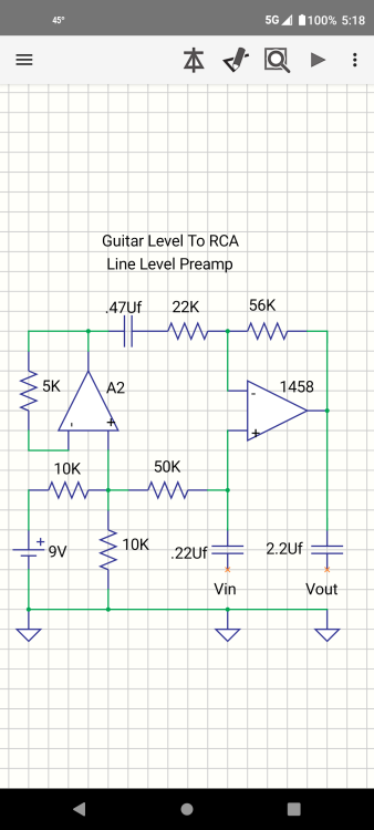
It's been a while, the Autobots have appeared on the silver screen. Finally they are returning to the big screen in their upcoming Transformers movie "Rise of the Beasts". This inspired me in making a PCB Badge to complement my enthusiasm and love towards the Autobots. In this tutorial, I am going to show you guys how to design this "Transformers PCB Badge" and how to solder the components to it. Components Required For this tutorial you need: 1 x 555 Timer IC 1 x 47KΩ Resistor 1 x 220Ω Resistor 1 x BC548 NPN Transistor 1 x 33µF Capacitor, and 1 x Few Blue LEDs Quick Recap In my last tutorial I created a "IC555 Led Fader Module" and explained how the circuit works. In this tutorial, I am going to use the same LED fader circuit to create a fading effect for the eyes of the badge. So before going ahead, lets do a quick recap and find out how the LED fader circuit works with the help of an animation. Circuit Diagram The heart of this circuit is the 555 timer IC. Pin No.1 of the IC is connected to GND. By connecting Pin 2 and 6 of the 555 timer IC, we put the IC in astable mode. In astable mode, the 555 timer IC acts as an oscillator (re-triggering itself) generating square waves [PWM Signals] from the output Pin no. 3. 3 other components connect to this junction. 1st one is the 33µF capacitor. The positive pin of the capacitor connects to the junction and the negative pin is connected to the GND. 2nd one is the 47KΩ resistor. One of its legs connects to the junction and the other leg connects to the Output pin, Pin No.3 of the IC. 3rd one is the Base of the BC548 NPN transistor. The collector of the transistor along with Pin 8 and 4 of the IC connects to the +ve terminal. of the battery. The LED along with its current limiting resistor is connected to the Emitter of the transistor. That's+- How The Circuit Works When Pin 2 of the IC detects voltage LESS than 1/3rd of the supply voltage, it turns ON the output on Pin 3. And, when Pin 6 detects voltage MORE than 2/3rds of the supply voltage, it turns OFF the output. This is how the trigger pin (Pin2) and the threshold pin (Pin6) of the 555 timer IC sense voltages and controls the output at Pin 3. The Capacitor attached to the circuit will be in a discharged state immediately after firing up the circuit. So, the voltage at Pin 2 will be 0v which is less than 1/3rds of the supply voltage, this will turn ON the output on Pin 3. Since Pin 3 is looped back to Pin 2, it will start charging the Capacitor via the 47KΩ resistor. At the same time the base current of the transistor also increases causing the LED to slowly "fade-in". Once the voltage across the capacitor crosses 2/3rds of the supply voltage, Pin 6 turns OFF the output. This causes the capacitor to slowly discharge causing the base current to fall and hence the LED starts "fading-out". Once the voltage across the capacitor falls below 1/3rd of the supply voltage, Pin 2 turns ON the output, and the above cycle continues. You can hook up a multimeter to the circuit to measure the charging and discharging of the capacitor. Designing The PCB Sorting Out Images To start the designing process, I need a transparent PNG image of the "Transformers Logo". So I went online, and did an "image search" and downloaded a black-and-white images of the Transformers Logo. Now, using the "Paint.Net" application I opened up the PNG file. The image onscreen will be used for: 1. Creating the border outline of the badge 2. and also for creating the face on top of the top silk layer To generate the "Border Outline" I need a DXF file. Looking at the image, we can see that the image is split into multiple parts. If I load this to generate a DXF file it will generate multiple pieces of the PCB. And obviously that's not what I am after. So, I joined all the small pieces into a single image. Generating DXF File Then, I uploaded the images to "https://convertio.co/" to generate the DXF files. This website allows 10 free conversions in a day unless you have a paid account with them. Creating the Badge Now, lets go ahead and add a "New PCB" to our project and remove the default board outlines. Then import the DXF files via File > Import > DXF menu. Make sure you have the "BoardOutLine" selected under layers when you import the DXF file. Now, lets import the image that will go on the Top Silk Layer. Select the "TopSilkLayer" and then import the image and move it inside the board outlines. Before going ahead, lets have a look at how the board looks like in 3D. As we can see the eyes and all other holes still have the blue PCB bits inside. So, let go ahead and remove them from our design. To do so, select the "MultiLayer" from the "Layers and Objects" panel. Then select "Solid Region" from the "PCB Tools" panel and start drawing the region you want to exclude from your PCB. That's it as easy as that. Checking the PCB in 3D, we can see that the top bit has now a see-through hole in it. I repeated this step, for all other bits that I wanted to excluded from my PCB design. Once the PCB design was sorted, I added all the electronic components to the board. Since I don't want any hole on my PCB, my choice was to either add SMD components on the board or to design the board in a way that I can solder THT components on it. I chose the second option and added all the THT components "however" without their holes. Instead of the holes I added some rectangles and circles from the "PCB Tools" panel on the "BottomLayer" and then exposed the copper. To finalize the design, I connected all the exposed pads as per the circuit diagram. That's it, all done. So, this is how the final design looks like. The Board So this is what came in the mailbag. Have a look at the quality, its absolutely mind-blowing. At the back of the board are all the exposed copper parts for soldering the electronic components. As mentioned earlier, I could have designed the board with SMD components, however I wanted to design something that someone with "0" SMD soldering knowledge can also do. Soldering Alright, now lets go ahead and solder the components to the board. Lets first soldered the 555 Timer IC to the board, then lets soldered the two resistors to the board. Next, lets soldered the 33µF Capacitor followed by the NPN transistor to the board. To conclude the setup lets soldered the 2 x LEDs to the board. You can power this circuit by providing voltage between 5V to 15Vs. Demo So, this is how the final setup looks like. You can insert the bottom bit of the badge to a wooden-plank and put this on your desk to give your desk a flashy look. Thanks Thanks again for checking my post. I hope it helps you. If you want to support me subscribe to my YouTube Channel: https://www.youtube.com/user/tarantula3 Video: Visit Full Blog Post: Visit LED Fader Using 555 Timer IC: Visit LED Fader - With or Without Arduino: Visit Adjustable Single/Dual LED Flasher Using 555 Timer IC: Visit Other Links: Gerber: Download Github: Visit Simulation: Visit What Is Forward Voltage: Visit Support My Work: BTC: 1Hrr83W2zu2hmDcmYqZMhgPQ71oLj5b7v5 LTC: LPh69qxUqaHKYuFPJVJsNQjpBHWK7hZ9TZ DOGE: DEU2Wz3TK95119HMNZv2kpU7PkWbGNs9K3 ETH: 0xD64fb51C74E0206cB6702aB922C765c68B97dCD4 BAT: 0x9D9E77cA360b53cD89cc01dC37A5314C0113FFc3 LBC: bZ8ANEJFsd2MNFfpoxBhtFNPboh7PmD7M2 COS: bnb136ns6lfw4zs5hg4n85vdthaad7hq5m4gtkgf23 Memo: 572187879 BNB: 0xD64fb51C74E0206cB6702aB922C765c68B97dCD4 MATIC: 0xD64fb51C74E0206cB6702aB922C765c68B97dCD4 Thanks, ca again in my next tutorial.
-
Ashish Adhikari changed their profile photo
-
Wanted to generate a LED fading effect (fade-in and fade-out) for my upcoming video tutorial using the 555 timer IC. I already have a video where I used LM358 Dual Operational Amplifier IC and another one with Arduino to generate the LED fading effect. YouTube, is full of video showing how to generate the fading effect using 555 timer IC. However, none of them produce a true fading effect. Some just fades-in but never fades-out. And there is literally no explanation of how they are generating the fading effect other than just showing how to assemble the components. In this tutorial, I am going to show you guys how to create a true LED fading effect using the 555 timer IC. I will also explain how the circuit works and how changing components change the fading effect of the LEDs. Components Required For this tutorial you need: 1 x 555 Timer IC 1 x 47KΩ Resistor 1 x 220Ω Resistor 1 x BC548 NPN Transistor 1 x 33µF Capacitor, and 1 x Few Blue LEDs Circuit Diagram The heart of this circuit is the 555 timer IC. Pin No.1 of the IC is connected to GND. By connecting Pin 2 and 6 of the 555 timer IC, we put the IC in astable mode. In astable mode, the 555 timer IC acts as an oscillator (re-triggering itself) generating square waves [PWM Signals] from the output Pin no. 3. 3 other components connect to this junction. 1st one is the 33µF capacitor. The positive pin of the capacitor connects to the junction and the negative pin is connected to the GND. 2nd one is the 47KΩ resistor. One of its legs connects to the junction and the other leg connects to the Output pin, Pin No.3 of the IC. 3rd one is the Base of the BC548 NPN transistor. The collector of the transistor along with Pin 8 and 4 of the IC connects to the +ve terminal. of the battery. The LED along with its current limiting resistor is connected to the Emitter of the transistor. That's it as simple as that. Alright, now I am going to demonstrate how this circuit works with the help of an animation. How The Circuit Works When Pin 2 of the IC detects voltage LESS than 1/3rd of the supply voltage, it turns ON the output on Pin 3. And, when Pin 6 detects voltage MORE than 2/3rds of the supply voltage, it turns OFF the output. This is how the trigger pin (Pin2) and the threshold pin (Pin6) of the 555 timer IC sense voltages and controls the output at Pin 3. The Capacitor attached to the circuit will be in a discharged state immediately after firing up the circuit. So, the voltage at Pin 2 will be 0v which is less than 1/3rds of the supply voltage, this will turn ON the output on Pin 3. Since Pin 3 is looped back to Pin 2, it will start charging the Capacitor via the 47KΩ resistor. At the same time the base current of the transistor also increases causing the LED to slowly "fade-in". Once the voltage across the capacitor crosses 2/3rds of the supply voltage, Pin 6 turns OFF the output. This causes the capacitor to slowly discharge causing the base current to fall and hence the LED starts "fading-out". Once the voltage across the capacitor falls below 1/3rd of the supply voltage, Pin 2 turns ON the output, and the above cycle continues. You can hook up a multimeter to the circuit to measure the charging and discharging of the capacitor. Breadboard Demo So, here is a quick demo on a breadboard. In the current setup I have a 33µF Capacitor and a Blue LED on the breadboard. Replacing the 33µF Capacitor with a 100µF Capacitor makes the LED fade in-and-out slower as the 100µF capacitor charges and discharges slower than 33µF Capacitor. Also by replacing the "Blue LED" with a "Red LED", we can make the LED to stay "on" longer than the blue one with the same value of capacitor. This is because the "Forward Voltage" (Vf) of the Blue LED is higher than that of the Red LED. "Forward voltage" is the minimum amount of voltage that is required to allow an electrical component to turn on. The red, green and yellow LEDs have relatively "low" forward voltage ranging from 1.6-2.2V and hence stays on longer when the capacitor slowly charges or discharged. However, blue and white LEDs starts conducting from 2.5-4V and hence, when the discharging capacitor's voltage hits the threshold the LED turns off faster than the other colors. I have provided a link to how the forward voltage works in the description below. If you connect few LEDs in series, the forward voltage adds up and hence it will require more voltage to turn on the LEDs. You need to add a current limiting resistor between the emitter of the transistor and the LED to avoid an internal short-circuiting inside the led. The Board To make it easy for you guys, I have created this tiny little "555 LED Fader Module". After assembling the components, you just need to power this module by providing a voltage between 5v to 15v to fade the LED. So, this is how my board looks like in 2D and 3D. There are 16 breakout boards in this 100cm x 100cm assembly. You can download the gerber file from the link provided in the description below and order it from PCBWay. Soldering Let me quickly show you guys how to assemble the components to this custom made board. Let's start by soldering the IC Base to the board. Then let's solder the two resistors to the board. Next, lets solder the capacitor followed by the transistor to the board. Then, lets solder a blue LED to the board. Once done, let's insert the 555 timer IC to the IC base. To conclude the setup, I soldered 2 x Female pin headers to the board. You can either solder a pair of female pin-header or male pin-header or solder a pair of wires directly to the board to power this module. Demo Cool, so this is how my module finally looks like. You can install female pin-headers in-place of the LED or Capacitor if you plan to use this as a development/testing board instead of a module. Thanks Thanks again for checking my post. I hope it helps you. If you want to support me subscribe to my YouTube Channel: https://www.youtube.com/user/tarantula3 Video: Visit Full Blog Post: Visit LED Fader - With or Without Arduino: Visit Adjustable Single/Dual LED Flasher Using 555 Timer IC: Visit Other Links: Gerber: Download Github: Visit Simulation: Visit What Is Forward Voltage: Visit Support My Work: BTC: 1Hrr83W2zu2hmDcmYqZMhgPQ71oLj5b7v5 LTC: LPh69qxUqaHKYuFPJVJsNQjpBHWK7hZ9TZ DOGE: DEU2Wz3TK95119HMNZv2kpU7PkWbGNs9K3 ETH: 0xD64fb51C74E0206cB6702aB922C765c68B97dCD4 BAT: 0x9D9E77cA360b53cD89cc01dC37A5314C0113FFc3 LBC: bZ8ANEJFsd2MNFfpoxBhtFNPboh7PmD7M2 COS: bnb136ns6lfw4zs5hg4n85vdthaad7hq5m4gtkgf23 Memo: 572187879 BNB: 0xD64fb51C74E0206cB6702aB922C765c68B97dCD4 MATIC: 0xD64fb51C74E0206cB6702aB922C765c68B97dCD4 Thanks, ca again in my next tutorial.
-
When you mix creativity with electronics, it becomes a masterpiece. Producing something original and worthwhile leads to the creation of a number of great new useful household products. In this video, I am going to show you guys how to create this Arduino based touchless concrete clock. 3D Design I always love to generate a 3D model of my product before creating it in real. This not only gives me a better view of what the final product is going to look like, but also helps me in finding the correct measurements of the final product. So, I went ahead and used the free "Windows 3D-builder" to generate this 3D model. The onscreen, black bar is where the TM1637 Digital Clock Module will sit. The gap in the circular concrete frame will house the 5 Blue LEDs that can be turned on or off my moving your hand over the IR Module. These two holes are for the IR Sensor Module. The concrete base bar will house all the remaining electronics components in it. The Template Based on my 3D-Model I designed this 2D-Template. You can download the template from the link provided in the description below and print it on a A4 paper. Template: Download Schematic Diagram Before going ahead, lets have a look at the schematic diagram of the digital clock. The heart of this circuit is an Arduino Nano. The TM1637 Digital Clock Module connects to D4 and D5 pin of the Arduino. The DS1302 RTC Module connects to the A1, A2 and A3 pin of the Arduino. The two White LEDs displayed on both sides of the digital clock connects to the D11 pin of the Arduino. These two LEDs flash 3 times every hour when the minutes counter is reset to "00". The IR module is connected to the D6 pin of the Arduino and controls the blue cluster of LEDs connected to D12 pin of the Arduino. My initial plan was to have 2 to 3 push button switches connected to D2 and D3 pin of Arduino to set the time of the clock. However in the final version, I did that by adding an extra line of code to my program. I will explain this in full details when we discuss the code. Preparing The Top - Concrete Using cardboard I created all the concrete molds. Cardboard was my first choice as it is very easy for me to cut and bend it into any shape of my choice. These holes in the mold you see are for the ribbon cables. Sticking this semi-circular piece on the left side of the inner circle will create the gap for the blue LED cluster when we pore the concrete into the mold. Alright, so this is how it looks like after putting all the pieces of cardboard mold together. Now, lets pour some "Brickies Sand" in-and-around the mold to hold it nice and tight when I pour the liquid concrete. Making the sand a bit wet, will make it firm and will also remove all the unwanted air from the sand. Cool, now lets go ahead and pour the concrete into the mold. Don't forget to compress the concrete mixture as you pour it. This way the concrete will reach all the necessary places and will also remove the unwanted air bubble from the mixture. I also added few "Nails" inside the mixture to give it a bit more firmness. This step was absolutely necessary, as my first design completely collapsed because it was not very sturdy. Once the setup dried up I removed all the sand and extracted the piece of art from it. Preparing The Top - Electronics Alright, now lets start installing the electronic components to the top section of the clock. The 4-Digit LED clock module will sit inside this gap. I will cover it up using a black plastic film which I extracted from a wrapping paper. For the back, I am using a compressed wood board. Based on my initial design I am going to make some holes in the board and install 3 x push button switches to it. The blue LED cluster will be hot-glued in the gap at the back of the circular section. I used a plastic cutout from a milk bottle to cover the Blue LED clusters. The white color of the plastic gave it a gloomy look, which was absolutely super awesome. I hot glues the two white LEDs to the backplate before putting it against the concrete. Frankly speaking, it was an absolute challenge for me to hot-glue the backplate on the camera. After struggling for a bit, I did that properly behind the scene. Preparing The Base - Concrete Now that we are done with the top section, lets start working on the base of the clock. For the base, I prepared 2 x cardboard boxes with open top one slightly shorter in height than the other. The 2 x straws you see on-screen will create the hole for the IR module. The hole on the side is for the AC power cable. The cardboard block I just added is to create a hole on the top of the base, where the circular-top will sit. Then it was just a matter of pouring the sand inside and outside of the cardboard molds followed by pouring the concrete mixture into it. Same as before I added some nails to give the structure some additional firmness. Once the concrete dried up, I extracted the concrete base from the sand and carefully sanded the structure to give it a nice and smooth texture. Preparing The Base - Electronics Okie-dokie, now lets install the rest of the electronic components inside the base of the clock. I used the same compressed wooden board to create the baseplate and then one by one soldered and hot-glued all the electronics components to it. The IR module I used in this project is one of my self made DIY IR modules. If you want to know more about the module, please checkout my Tutorial No 21 - All About IR Modules and how to make your own DIY IR Module. Joining The Base To The Top Now that we have top and the bottom ready, lets go ahead and join them together. I created this cardboard thing to hold the concrete, when I pour the concert in the hole. This cardboard block will also prevent me from poring excessive concrete inside the hole. The flap in the middle is to hold the wires preventing them from getting mixed up with the concrete. After pouring the concrete I left it of drying for almost 2 days. Code While the concrete was drying up, I complied and uploaded the code to the Arduino. For this project you need include the "ArduinoRTClibrary" and the "TM1637Display" libraries in your code. You can download them from github from the link provided in the description below. Lets start the code by creating an instance of the RTC module followed by defining the variables used by the RTC module. Then, define all the LED pins followed by creating an instance of the TM1637 module and defining all the variables used by the module. Next, define the pins used by the IR module. In the setup section, the 1st two lines can be used to attach an interrupt to the code, if you are planning to use the push button switches. However, in my code I am not using the buttons, so I commented them out. Next, I have set the brightness of the display to the max value = 7 and added the "showNumberDecEx" function to include the colon in the code. Next, I defined all the pin modes used by the attached components in the code. The code below can be used to set the time of the clock. Set the correct time, uncomment and then load the code. Once loaded, comment the lines and then load the rest of the code. // Set the current date, and time in the following format: // seconds, minutes, hours, day of the week, day of the month, month, year //myRTC.setDS1302Time(00, 39, 21, 7, 20, 1, 2023); In the loop section, all we are doing is - reading the hour and minutes from the RTC module and displaying it on the 7-Segment display. myRTC.updateTime(); // This allows for the update of variables for time or accessing the individual elements minutes = myRTC.minutes; // Get the current minutes from the RTC Module hours = myRTC.hours; // Get the current hours from the RTC Modules timeData = hours * 100 + minutes; This code block is used to toggle the colon on and off. // Code block that blinks the colon of the TM1637 module if (ctr == 200) { if (blinkToggle) { display.showNumberDecEx(timeData, 0x40, true); blinkToggle = false; } else { display.showNumberDecEx(timeData, 0, true); blinkToggle = true; }; ctr = 0; };ctr++; delay(5); This section is used to read the value of the IR sensor and either turn on or turn off the blue LED clusters. // Code block that turns on or off the Blue LED Cluster int Sensordata = digitalRead(IRSensor); // Set the GPIO as Input if (Sensordata != 0) { if (millis() - timestamp>500) { // This is to avoid multiple obstacle detection timestamp = millis(); if (IRtoggler == 0) {digitalWrite(LED_BLUE, HIGH);IRtoggler = 1;} else {digitalWrite(LED_BLUE, LOW); IRtoggler = 0;} }; }; This bit of the code, is to flash the white led when the minute counter resets to 0. // Flash the white LEDs if minutes = 0 if ((int)minutes == 0) { if (blinkCTR==0 || blinkCTR==40 || blinkCTR==100 || blinkCTR==140 || blinkCTR==200 || blinkCTR==240 || blinkCTR==300 || blinkCTR==340) digitalWrite(LED_WHITE, HIGH); if (blinkCTR==20 || blinkCTR==60 || blinkCTR==120 || blinkCTR==160 || blinkCTR==220 || blinkCTR==260 || blinkCTR==320 || blinkCTR==360) digitalWrite(LED_WHITE, LOW); blinkCTR++; }; if ((int)minutes == 1) blinkCTR = 0; // Reset blinkCTR for the next cycle of flashing If you are planning to use the 2 x push button switches to set the time or to set an alarm, go ahead and uncomment this bit of the code and add your code block to it. // Pressing this button puts the clock in setup mode //void Button_1_Pressed(){}; // Pressing this button increments the values on the display //void Button_2_Pressed(){}; Final Demo So this is how it finally looks like. Do comment and let me know if there are any scopes of improvement. Thanks Thanks again for checking my post. I hope it helps you. If you want to support me subscribe to my YouTube Channel: https://www.youtube.com/user/tarantula3 Video: https://youtu.be/AQhBpQrfmg8 Full Blog Post: https://diy-projects4u.blogspot.com/2023/02/ArduinoClock.html Other Links: Template: Download 3D Model: Download Github: Visit ArduinoRTClibrary: Download TM1637Display Library: Download Support My Work: BTC: 1Hrr83W2zu2hmDcmYqZMhgPQ71oLj5b7v5 LTC: LPh69qxUqaHKYuFPJVJsNQjpBHWK7hZ9TZ DOGE: DEU2Wz3TK95119HMNZv2kpU7PkWbGNs9K3 ETH: 0xD64fb51C74E0206cB6702aB922C765c68B97dCD4 BAT: 0x9D9E77cA360b53cD89cc01dC37A5314C0113FFc3 LBC: bZ8ANEJFsd2MNFfpoxBhtFNPboh7PmD7M2 COS: bnb136ns6lfw4zs5hg4n85vdthaad7hq5m4gtkgf23 Memo: 572187879 BNB: 0xD64fb51C74E0206cB6702aB922C765c68B97dCD4 MATIC: 0xD64fb51C74E0206cB6702aB922C765c68B97dCD4 Thanks, ca again in my next tutorial.
-
Ashish Adhikari reacted to a post in a topic:
DIY - ARDUINO BASED CAR PARKING ASSISTANT
-
Created a small "PCB Christmas Forest" which is going to light up my study table this Christmas. In this video, I am going to show you guys how to design these PCBs and assemble them to create a small PCB Christmas Forest. Designing The PCBs Sorting Out Images To start the designing process, I need transparent PNG images of the Christmas Tree, Star, Snowflake, Candy Cane etc. So I went online, and did an "image search" and downloaded few black-and-white images of all the items that I need to design these PCBs. Using the good old "MS Paint" I edited all these PNG files. I removed the rounded base and made the base flat so that it easily sits on the base plate. Then I removed a small portion from the bottom to expose a bit of copper. Pouring a blob of solder on this plate will hold the PCB nice and tight from the front side on the baseplate. In my design I have 3 different sizes of the trees. If you look closely, they are all extracted from the same tree by removing the bottom layer each time and hence generating a new size of the tree. Generating DXF File For the customized shapes of the PCBs, we need to generate "DXF files" to set the "Board Outlines". I am using the "paint.net" application to fill in the white spaces of the tress as I only need the borders and nothing else from the original images. Then, I uploaded the images to "https://convertio.co/" and generated the DXF files. This website allows 10 free conversions in a day unless you have a paid account with them. Creating the Trees Now, lets add a "New PCB" to our project and remove the default board outlines. Then import the DXF files via File > Import > DXF menu. Make sure you have the "BoardOutLine" selected under layers when you import the dxf file. Now lets import the image that will go on the Top Silk Layer. Put the image over the board outline and move it to the "TopSilkLayer". Then lets go ahead and decorate our tree. Once all set, lets hide the Top Silk Layer so that we can work on the rest of items. Using the Rectangle tool from the "PCB Tools Plate" I added a rectangle to the bottom of the PCB. I exposed the copper, so that I can use this to hold the tree on the baseplate by poring a blob of solder on it. Next I randomly added few LEDs here and there at the bottom side of the board. Then I added few exposed copper rectangles at the back side of the board and connected them the LEDs. Remember this is just an example, the attached gerber is totally different from what you see onscreen. So, this is how the tree looks like in 3D. Creating the Baseplate Now to create the baseplate, we again need to add a "New PCB" to our project and remove the default board outlines. Then go to Tools > Set Board Outline.. and select the "Round Rectangular" from the "Type" selection. Specify the height, width and the radius of the edge and hit the "Apply" button. Then go-ahead and add the rest of the components one by one either to the "TopLayer" or the "BottomLayer" of the board and connect them using wires. I grabbed the back and the front exposed rectangles from the tree and added them to the baseplate. This way the spacings will remain intact when we solder the trees on the baseplate. That's it easy as that. Now just go ahead and download your gerber file and send it for fabrication. So, this is how my baseplate looks like. Bit complex, but it has the exact same logic that I just showed you guys. Ordering Process Once I had my design ready, I just had to upload the gerber file to the PCBWay's website and select the type, color and any other customization that I want and then just send it for fabrication. For my project, I choose the black, red and the green colors. The Code The code I wrote is very simple. I have just turned on and off the LEDs after a 500ms delay. The top white LEDs turn on and off in the opposite order to the rest of the LEDs. This code is just an example, you can write all sorts of funky stuff and load it to your Arduino board. Testing on Breadboard I tested my code on a breadboard before soldering the LEDs to the board. I wanted to see if the Arduino Nano can handle that many LEDs at once and I also wanted to check if combining different color LEDs on a same pin of Arduino will have any adverse effect. The result was pretty promising: - I was able hook up 3 LEDs without any issues to all the Digital (except D13) and Analogue pins of the Arduino. - I was "not" able to combine yellow and orange LEDs with any other color on the same pin of Arduino. Soldering So, this is what came in the mailbag. Have a look at the quality, its absolutely mind-blowing. Based on my design, the black one will stay at the back, the green one on right and the red one on the left hand side of the baseplate. Please make sure when you solder the trees, solder the small (red) one first, then the green one and finally the big black one at the back. This way, you will be able to solder them very easily, without going over or under the trees. Now, lets start soldering. Lets start by soldering the LEDs on the trees. Since the front side of the plate has all the decorations on it, I placed all the component markings at the back side of the plate. I then one by one soldered all the LEDs on the front side of the plates. Please be careful while adding the colors, as mentioned earlier you cannot hook up yellow and orange with any other color on the same pin of an Arduino. Please follow my final coloring patter. Now lets get the baseplate sorted. Lets start by soldering all the resistances to the board. Then, lets solder 2 x female pin headers to the board. These pin headers will house the Arduino Microcontroller in it. After that, lets solder the 2 pin micro-USB port to the board. Next, its time to solder the trees to the board. With lots of flux and very little solder this is what I ended up creating. Since a lot of the LEDs were getting hidden behind the trees, I ended up removing a lot from the final version. Just follow the onscreen color pattern and you will have a small Christmas forest sitting on your table in less than 30 minutes. Merry Christmas and Happy New Year... Thanks Thanks again for checking my post. I hope it helps you. If you want to support me subscribe to my YouTube Channel: https://www.youtube.com/user/tarantula3 Video: Video Link Full Blog Post: Blog Post Code: Download Image Resources : Download Gerber Base : Download Gerber Small Tree : Download Gerber Medium Tree : Download Gerber Big Tree : Download GitHub : Visit Support My Work: BTC: 15cNh9hup8jidCVPwa1DTcxeoh2FPijVrX LTC: LbquH9Ku78vHtcm3LZnWXpD1JQWdKzeV4v DOGE: DEB2QBAihnBRhGsaB8P7kz559TDiucQhX6 ETH: 0x5d8c9ba0e54d8354d4af81871db26daa190d2194 BAT: 0x939aa4e13ecb4b46663c8017986abc0d204cde60 LBC: bZ8ANEJFsd2MNFfpoxBhtFNPboh7PmD7M2 COS: bnb136ns6lfw4zs5hg4n85vdthaad7hq5m4gtkgf23 Memo: 572187879 BNB: 0x5d8c9ba0e54d8354d4af81871db26daa190d2194 Thanks, ca again in my next tutorial.
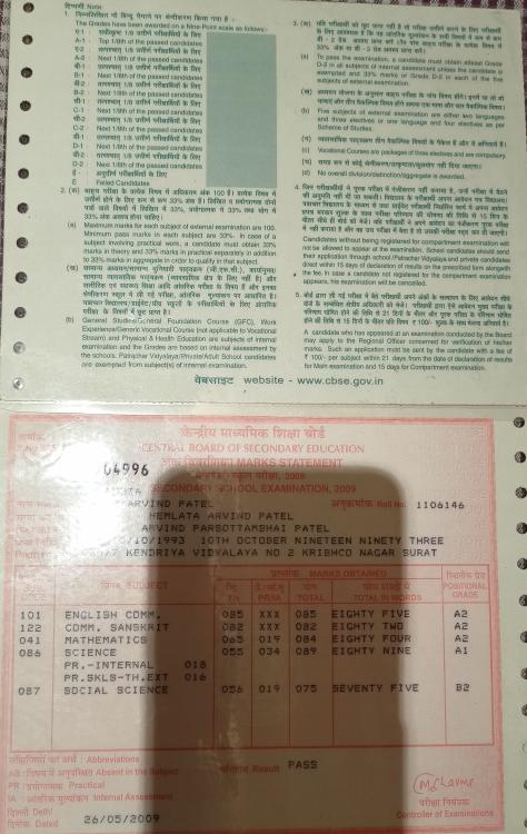


-
Intro In my hand is a 4-Digit 7-Segment display module. The heart of this module is an inexpensive Serial LED Driver from Titan Micro Electronics called the TM1637. In this tutorial, I am going to show you guys how to control the TM1637 4-Digit 7-Segment displays using an Arduino. If you want to displays sensor data, temperature and humidity, or want to design a clock, timer or counter, you will need this 4-Digit Seven-Segment Display. Topics Covered In this tutorial we are going to talk about: The Basics of a 7-Segment Display Hardware Overview and Pinout of The TM1637 Module TM1637 Library Installation Interfacing TM1637 Module with an Arduino Loading The Basic Arduino Code (that comes with the TM1637 library) Then we will have a look at some of these quick examples: Example 1: Displaying String and a Number Example 2: Displaying Scrolling and Blinking Text Example 3: Creating a 4 Digit Counter Example 4: Displaying Temperature & Humidity using DHT11/DHT22 Example 5: Creating an Arduino Based Digital Clock And finally we will have a look at some common errors. 7-Segment Display Basics A 7-Segment Displays consists of 7 LEDs making the shape of decimal number 8. These LEDs are called segments, because when they light up, each segments contributes in the formation of part of a decimal or hex digit. These individual segments are labeled from ‘a’ to ‘g’ representing each individual LED. By setting a particular segment HIGH or LOW, a desired character pattern can be generated. Hardware Overview and Pinout of TM1637 Module The module comes with 4 right angle male pin headers. I find it a bit annoying to have the pin headers on the top side of the board. However, you can always unsolder and put them at the bottom of the board. Now lets have a look at the GPIO pins: CLK - is the clock input pin. You can connect it to any digital pin of an Arduino. DIO - is the Data I/O pin. This can also connect to any digital pin of an Arduino. VCC - Connects to 3.3V to 5V power supply. GND - is the ground pin. CLK and DIO pins can be connected to any digital pin of an Arduino. This gives us an opportunity to hook up a lot of these modules to an Arduino, as long as each instance has a pin pair of its own. When writing the code, we just need to specify the pin pair and then just go ahead and use them in your project. If you run out of pins on your Arduino board you can use a GPIO Pin Extenders like the PCF8574. Please check out my tutorial on the Extender module, the link is in the description below. PCF8574 GPIO Extender: https://diyfactory007.blogspot.com/2018/12/pcf8574-gpio-extender-with-arduino-and.html The module has 4 x 0.36 segment 7-Segment Displays and a ‘colon’ at the center for creating clock or time-based projects. A bare four digit 7-Segment Displays usually requires 12 connection pins but the TM1637 LED Driver removes the need of the extra wiring for the 7-Segments and the entire setup can be controlled just by using 2 wires (DIO and CLK) and two more for power reducing the total wires to 4. These modules communicate with the processor using "I2C-like protocol". The implementation is pure software emulation and doesn't make use of any special hardware (other than GPIO pins). The module operates between 3.3v to 5v with a current consumption of 80ma and allows adjusting the brightness of the LEDs at the software level. They are available in few different colors. TM1637 Library Installation There are many libraries available for the TM1637 module. For this tutorial, we are going to use the "TM1637Display Library" written by "Avishay Orpaz". You can download the library using the library manager or from Github, the link is in the description below. To install the library using "Library Manager", navigate to Sketch > Include Library > Manage Libraries… Search for "TM1637" and look for the one by "Avishay Orpaz". Hit the "Install" button to install the library on your device. TM1637Display Library: Download Interfacing TM1637 Module with an Arduino Hooking up the TM1637 module to an Arduino is very easy. You just need to connect four wires: 2 for power and other 2 for controlling the display. You can connect the VCC of the module to either 3.3v or 5v pin of the Arduino. So, connect: CLK - Pin 2 of Arduino DIO - Pin 3 of Arduino VCC - 5V of Arduino GND - GND of Arduino As previously advised, you can use any pin combination for the CLK and DIO on the Arduino board. Just make sure you change the pin numbers in the code to reflect the change of wiring. So far, based on my experience I have only found one disadvantage. This module is unable to display floating points or dots between numbers. However, you can use the "HT16K33 module" for displaying floating points. Loading The TM1637Test Example Before going ahead, lets have a look at the example that comes with the TM1637 Library. Navigate to File > Examples > TM1637 and load the "TM1637Test" example. The sketch starts by including the "TM1637Display.h" library. Then it defines the CLK and the DIO pins that will be used to connect the TM1637 display. In this example Pin-2 of Arduino is used for CLK and Pin-3 for DIO. Next, you need to create a new instance of the "TM1637Display" class by passing the CLK and the DIO Pin values to it. Then, the code shows us 2 ways of displaying data on the individual segments by creating arrays of texts. a. 1st by passing "hexadecimal numbers" to the individual displays Passing "0xff" to all the 4 displays will turn them all ON, and passing "0x00" will turn them all OFF. Using the "display.encodeDigit()" function you can display digits between 1 and 15. This will display F___ on the display. b. 2nd by individually specifying the segments that you want to turn on. The below creates an array that sets the individual segments values and displays "dOnE" on the display. Now, to display these arrays, you need to pass them to the "display.setSegments()" function. The setSegments function accepts 3 arguments Data = The data to display Length = number of digits to be updated (0–4). Ex. for "dOnE", it will be 4, for the "°C" it will be 2. Position = determines the position from which you want to print (0-leftmost, 3-rightmost). Remember, the LEDs once turned on stays on until they are turned off. So, you always have to clear the previous value before displaying the new one. This can be done by passing 4 lots of 0xffto the "display.setSegments()" function or by using "display.clear()" function. The brightness of the display can be adjusted using the "setBrightness()" function. The function accepts values between 0 (lowest) to 7 (highest). The "display.showNumberDec()" function is the function that you are going to use the most to display numbers on the module. The first argument is a number that you want to display on the screen. The rest of the arguments are all optional. Syntax: Number = The number that you want to display on the screen. Values up to 9999 (type integer). Leading_Zeros = True/false. Setting it to True will add leading zeroes. Default value is false. Length = number of digits to be updated (0–4). Ex. for "dOnE", it will be 4, for the "°C" it will be 2. Position = determines the position from which you want to print (0-leftmost, 3-rightmost). Example: Template For the rest of the examples, I am going to use this template to write the code. I will only show you guys the bit which is different in each code. Example 1: Displaying Strings and Numbers In this example you can see letter "TEST" and a randomly generated number is alternating and getting displayed on the screen. To display the letter TEST, I am first clearing the screen and then lighting up the individual segments to display the characters. To display a number, I am first generating a random number between 0 and 9999 and then displaying it using the "display.showNumberDec()" function. Example1: Download Example 2: Displaying Scrolling and Blinking Text Now, to display a scrolling text, I am incrementing the position of the text by 1 and then displaying it from the new position. You need to pad the display with any character or it will end up showing random characters on the display. Blinking a text is super easy. All you have to do is display the text, add a delay, clear the screen and then again add a delay before displaying the text again. Example2: Download Example 3: Creating a 4 Digit Counter To display a counter, I am looping from 0 to 9999 and displaying the incremented value every time on the 7-Segments. You can also add a push button switch to start and stop the counter. Example3: Download Example 4: Displaying Temperature & Humidity using DHT11/DHT22 Connect the OUT pin of the DHT11/DHT22 sensor to Pin-5 of the Arduino. Then in the code include the "DHT.h" library and define the DHTPIN and the DHTTYPE. Next, create a DHT object and in the setup section initialize the DHT sensor using the "dht.begin()" function. Next in the loop section read the sensor data using the "dht.readTemperature()" function and display it on the 7-Segments. Example4: Download Example 5: Creating an Arduino Based Digital Clock You can also create an alarm clock using either the DS3231 or DS1302 RTC Module and display the data using this TM1637 module. I will cover that in full details in my next video. Common Errors Now lets have a look at some off the common errors: Display showing parts of the previous data. You always have to clear the previous value before displaying the new one. You can either use: or Display data going out of the display or showing partially Check the positioning of the display data. These are few of the issues that I came across while playing around with these displays. Do comment and let me know if you have any more to add to the list. Thanks Thanks again for checking my post. I hope it helps you. If you want to support me subscribe to my YouTube Channel: https://www.youtube.com/user/tarantula3 Links: Video: Video Link https://youtu.be/Ob9mrq_Lj9k Full Blog Post: Blog Post Datasheet: Download Schema: Download TM1637Display Library: Download Thingiverse : Download PCF8574 GPIO Extender: Blog Post Code: Example1: Download Example2: Download Example3: Download Example4: Download TM1637Test: Download Template: Download Support My Work: BTC: 15cNh9hup8jidCVPwa1DTcxeoh2FPijVrX LTC: LbquH9Ku78vHtcm3LZnWXpD1JQWdKzeV4v DOGE: DEB2QBAihnBRhGsaB8P7kz559TDiucQhX6 ETH: 0x5d8c9ba0e54d8354d4af81871db26daa190d2194 BAT: 0x939aa4e13ecb4b46663c8017986abc0d204cde60 LBC: bZ8ANEJFsd2MNFfpoxBhtFNPboh7PmD7M2 COS: bnb136ns6lfw4zs5hg4n85vdthaad7hq5m4gtkgf23 Memo: 572187879 BNB: 0x5d8c9ba0e54d8354d4af81871db26daa190d2194 Thanks, ca again in my next tutorial.