
sam.moshiri
-
Posts
60 -
Joined
-
Last visited
-
Days Won
2
Content Type
Profiles
Forums
Events
Posts posted by sam.moshiri
-
-
The key part of any electronic device is the power supply. Any instability or malfunction of the power supply part causes the device to stop working or demonstrate weird behavior. In this article/video, I introduced an AC-to-DC flyback Switching power supply that converts 85V-260VAC to 5VDC-2.5A, which can be used in various applications. The 5V selection for the output makes it friendly for linear regulators that convert 5VDC to lower voltages.
The maximum power delivery of this power supply is around 12W, which means it can handle 2.5A at 5V output. The controller chip is DK1203, which does not need any external supply, a startup resistor, or an auxiliary winding on the transformer. The ferrite core of the transformer is EE20. A potentiometer allows you to adjust the output voltage and set it exactly at 5.0V.
To design the schematic and PCB, I used Altium Designer 23 and shared the PCB project with my friends for feedback and updates using Altium-365. The fast component search engine, Octopart, proved invaluable in quickly obtaining component information and generating the Bill of Materials (BOM). To ensure high-quality fabricated boards, I sent the Gerber files to PCBWay.
I tested the board for voltage drop, current delivery, and output noise. I used Siglent SDL1020X-E DC Load and Siglent SDS2102X Plus oscilloscope to perform all tests. I am confident that building this circuit enhances your knowledge regarding switching power supply design, except for using it for real applications.Schematic + PCB + Transformer: https://www.pcbway.com/blog/technology/85V_260VAC_to_5VDC_2_5A_Flyback_Switching_Power_Supply_b7f49beb.html
References
[1]: DK1203: https://grupoautcomp.com.br/wp-content/uploads/2016/11/Specification-IC-DK1203.pdf
[2]: 500mA Fuse: https://octopart.com/39211000440-littelfuse-39590771?r=sp
[3]: 07D471 Varistor: https://octopart.com/mov-07d471ktr-bourns-19184728?r=sp
[4]: 100nF X2: https://octopart.com/r463i310050m1k-kemet-50550056?r=sp
[5]: UU9.8 Choke: https://octopart.com/7355-h-rc-bourns-12614152?r=sp
[6]: MB6M Bridge: https://octopart.com/mb6m-e3%2F45-vishay-42761003?r=sp
[7]: 22uF-400V: https://octopart.com/eca2ghg220-panasonic-3578224?r=sp
[8]: RS1M Diode: https://octopart.com/rs1m-13-f-diodes+inc.-333072?r=sp
[9]: PC817 Optocoupler: https://octopart.com/pc817xnnsz1b-sharp-80823687?r=sp
[10]: TL431 Shunt: https://octopart.com/tl431acdbvr-texas+instruments-521839?r=sp
[11]: SS54 Schottky Diode: https://octopart.com/ss54-multicomp-18903925?r=sp
[12]: 470R-1206: https://octopart.com/cr1206-jw-471elf-bourns-3872844?r=sp
-
-
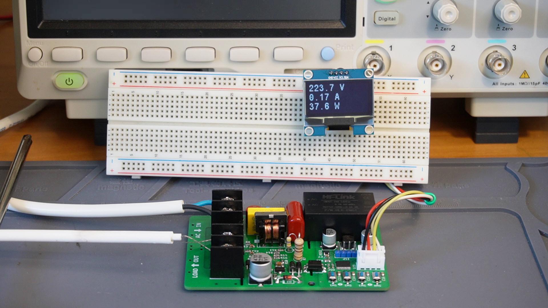
Dealing with the 110V/220V AC mains voltage and measuring the AC load parameters are regarded as a challenge for electronic designers, both in circuit design and calculations. The situation becomes more complex when dealing with inductive loads because they cause a phase shift between voltage and current and alter the sine-wave shape of the AC signal (resistive loads do not). The power factor of resistive loads is theoretically equal to 1.
In this article/video, I introduce a circuit that can measure AC RMS voltage, RMS current, active power, power factor, and energy consumption (KWh) of the loads. I used a low-cost STM32 Microcontroller and provided four push buttons for initial calibration. The device can independently measure the parameters and display the results on a bright 1.3-inch OLED display. The measurement error rate is around 0.5% or lower.
For the schematic and PCB design, I use Altium Designer 23. I shared the PCB project with my colleague for feedback and edits through Altium 365's secure cloud space. The Octopart component search engine proves invaluable for obtaining component information and generating the Bill-of-Materials (BOM). To ensure the production of high-quality fabricated boards, I forwarded the Gerber files to PCBWay. I used the Siglent SDM3045X benchtop multimeter to calibrate the circuit. That’s a quick and easy process.
It's a cool device for everyday electronics, so let’s get started! 🙂
References
Schematic + PCB + BOM: https://www.pcbway.com/blog/technology/Digital_AC_Energy_Measurement_Circuit_V2_RMS_Voltage_RMS_Current_Real_Power_P_a1bf4da8.html
[1]: Littelfuse 500mA: https://octopart.com/37005000410-littelfuse-39623899?r=sp
[2]: MOV-07D471K: https://octopart.com/mov-07d471ktr-bourns-19184728?r=sp
[3]: Bourns 7355-H-RC: https://octopart.com/7355-h-rc-bourns-12614152?r=sp
[4]: 100nF-X2: https://octopart.com/r46kf310000p1m-kemet-20074740?r=sp
[5]: 470nF-630V: https://octopart.com/ecw-fa2j474j-panasonic-22311695?r=sp
[6]: 1N4007: https://octopart.com/ecw-fa2j474j-panasonic-22311695?r=sp
[7]: 78L05 SOT89: https://octopart.com/ua78l05acpk-texas+instruments-525167?r=sp
[8]: HLK-PM01: https://octopart.com/hlk-pm01-hi-link-122345845?r=sp
[9]: SPX3819M5: https://octopart.com/spx3819m5-l-3-3%2Ftr-maxlinear-94414540?r=sp
[10]: PC817: https://octopart.com/pc817x1nip1b-sharp-80968503?r=sp
[11]: STM32G030F6: https://octopart.com/stm32g030f6p6-stmicroelectronics-103773023?r=sp
[12]: 16MHz XO: https://octopart.com/ecs-3225mv-120-cn-tr-ecs+international-95544585?r=sp
[13]: 2N7002: https://octopart.com/2n7002-diotec-109206764?r=sp
-
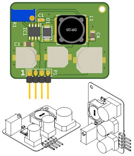
DC-to-DC buck converters are utilized ubiquitously in electronic devices. Three major types of non-isolated DC-to-DC converters are introduced: Buck, Boost, and Buck-Boost. The most frequently employed type is the Buck converter. In this article/video, I introduce a compact buck converter board, capable of accepting input voltages ranging from 8V to 95V and handling 5V-1A at the output.
The selected controlling chip is the MP9486. It is a high-frequency and somewhat sensitive controller chip as some users reported encountering instability issues. However, I have applied a few modifications to the circuit and as a result, you can utilize this circuit, PCB, or assembled board without any issues. The circuit offers consistent regulation within the defined input voltage range, effectively managing the maximum output current.
For the schematic and PCB design, I utilized Altium Designer 23. I shared the project with my colleague for feedback and edits through Altium 365's secure cloud space. The Octopart component search engine proved invaluable for obtaining component information and generating the Bill of Materials (BOM). To ensure the production of high-quality fabricated boards, I forwarded the Gerber files to PCBWay.
I tested the circuit's performance for a range of input voltage, output current, stability, and output noise. This comprehensive testing was conducted using the Siglent SDL1020X-E DC Load, the SDM3045M multimeter, and the SDS2102X Plus oscilloscope.
I am confident that this circuit fulfills your requirements for a compact high-voltage buck converter board.
References
Schematic + PCB: https://www.pcbway.com/blog/technology/8_100V_to_5V_1A_DC_to_DC_Buck_Converter_using_MP9486_5a0e0270.html[1]: MP9486: https://octopart.com/mp9486agn-z-monolithic+power+systems-89568395?r=sp
[2]: SS110 SMA: https://octopart.com/ss110b-multicomp-18903920?r=sp
[3]: 33uH TDK: https://octopart.com/slf7045t-330m1r1-h-tdk-7629956?r=sp
[4]: 0805 R LED: https://octopart.com/150080rs75000-wurth+elektronik-29717781?r=sp -
433MHz/315MHz remote controls are everywhere around us, used to control devices such as turning ON/OFF the lights or a TV, or in applications such as opening/closing parking or villa entrance, … etc. Such remotes are available in the market in various shapes and sizes; however, most are equipped with four buttons. In this article/video, I introduce a full-featured four channels wireless switcher device that can be paired with the majority of 433MHz or 315MHz wireless remotes in the market. The board can store up to 80 remote control buttons/codes (20 remotes with four buttons) in its EEPROM memory. You can easily record, delete, decode, and assign any individual remote-control button.
The board is compact and equipped with a small 2*8-character LCD, enhancing the user experience. Any remote-control button can be assigned to any of the four relays to activate and deactivate the devices. An ATMega8 microcontroller is the heart of the circuit. I used the Arduino IDE to develop the code. The most challenging part of this project was dealing with EEPROM memory. Eventually, I decided to use the structures to tackle it. Powering the board is as simple as connecting a 9V-1A power adapter.
For the schematic and PCB design, I utilized Altium Designer 23 and shared the project with my friends for feedback and edits using Altium-365's secure cloud space. The fast component search engine, Octopart, proved invaluable in quickly obtaining component information and generating the Bill of Materials (BOM). To ensure high-quality fabricated boards, I sent the Gerber files to PCBWay. I am confident that this circuit meets your requirements for a compact switcher board.
References
schematic + pcb + code: https://www.pcbway.com/blog/technology/433MHz_4_Channels_Wireless_Switcher_Circuit_a1dc8b5e.html
[1]: ATMega8-16PU: https://octopart.com/atmega8-16pu-microchip-77760540?r=sp
[2]: L7805, TO-263: https://octopart.com/l7805abd2t-tr-stmicroelectronics-526655?r=sp
[3]: 78L05, SOT-898: https://octopart.com/ua78l05acpk-texas+instruments-525167?r=sp
[4]: Ferrite Bead: https://octopart.com/blm31pg121sn1l-murata-368354?r=sp
[5]: 16MHz Crystal: https://octopart.com/hc49sm-16-30-50-60-16-atf-multicomp-8601779?r=sp
[6]: LM1-5D Relay: https://octopart.com/lm1-5d-rayex-53719411?r=sp
[7]: 1N4007, DO-214AC: https://octopart.com/1n4007+smd-multicomp-104895004?r=sp
[8]: Si2302 MOSFET: https://octopart.com/si2302cds-t1-e3-vishay-44452855?r=sp
-
The most important part of any electronic device is the power supply section. Any instability or malfunction in this part causes the device to stop its operation or show weird behavior. In this article/video, I introduced an AC to DC Flyback Switching power supply that converts 220V-AC to 8V-DC, which can be used in a variety of applications. The 8V selection for the output makes this supply friendly for any type of linear regulator.
The maximum power delivery of this power supply is 24W, which means it can handle 3A at 8V output. The controller chip is DK125, which does not need any external supply, a startup resistor, or even an auxiliary winding on the transformer. The transformer's ferrite core is RM8, which differs from most supplies using EE or EI cores. A small potentiometer allows you to adjust the output voltage and set it to 7.5 to 8V.
For the schematic and PCB design, I utilized Altium Designer 23 and shared the project with my friends for feedback and updates using Altium-365. The fast component search engine, Octopart, proved invaluable in quickly obtaining component information and generating the Bill of Materials (BOM). To ensure high-quality fabricated boards, I sent the Gerber files to PCBWay.
I tested the board for voltage drop and current delivery, output noise, and load step response. I used the Siglent SDL1020X-E DC Load, Siglent SDS2102X Plus oscilloscope, Siglent SDM3045X multimeter, and Siglent CP4020 current probe to perform all tests. I am confident that this circuit will meet your requirements for a compact and efficient power supply, providing reliable performance on your electronics bench.
References
[1]: DK125: https://datasheet.lcsc.com/lcsc/2111241030_Shenzhen-DongKe-Semicon-DK125_C171868.pdf
[2]: 100nF-X2: https://octopart.com/r463i310050m1k-kemet-50550056?r=sp
[3]: 10mH CM Choke: https://octopart.com/7355-h-rc-bourns-12614152?r=sp
[4]: DB107 BR: https://octopart.com/db107g-genesic+semiconductor-19909514?r=sp
[5]: 22uF-400V: https://octopart.com/db107g-genesic+semiconductor-19909514?r=sp
[6]: RM8 Core: https://octopart.com/b65811j0160a087-epcos-66666588?r=sp
[7]: 0805 Yellow LED: https://octopart.com/150080ys75000-wurth+elektronik-29717784?r=sp
[8]: TL431ACDB: https://octopart.com/tl431acdbzr%2C215-nexperia-78742091?r=sp
[9]: PC817: https://octopart.com/pc817x1nip1b-sharp-80968503?r=sp
-
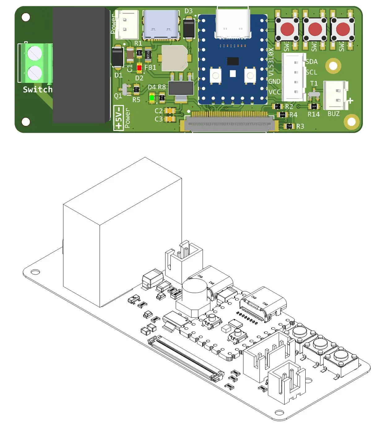
In this article/video, I used an RP2040 Zero board, a VL53L0X Laser time-of-flight ranging sensor, and a 2.4” TFT display to build a graphical laser rangefinder unit that can be used to monitor the distance, check the liquid level, etc. The board is also equipped with a relay and a buzzer that allow the user to provide distance-related acoustic signals or activate/deactivate an external device, such as a pump, brake, etc.
Source: https://resources.altium.com/p/rp2040-zero-powered-laser-range-finder-gui-and-24-tft-display
-
On 6/4/2023 at 6:10 AM, loribennms said:
It sounds like you have put a lot of effort into designing and implementing your power supply using the TPS54202 buck converter. Your choice of components, such as input and output filters, along with PCB design techniques, demonstrates your commitment to achieving low noise levels and high performance. Utilizing Altium Designer 23 and Altium-365 for schematic and PCB design collaboration is a smart choice. Octopart's component search engine and generating the Bill of Materials (BOM) streamlined your component selection process. Sending the Gerber files to PCBWay ensures high-quality fabrication. Testing the circuit for output noise and load step response using Siglent oscilloscope and DC load adds credibility to your design's functionality. Overall, your dedication to creating a compact and efficient power supply for electronics applications is commendable. It seems like you have taken all the necessary steps to ensure reliable performance on your electronics bench.
Yes I put a fat amount of effort for my content
-
A power supply is an essential tool on every electronics bench. The TPS54202 is a highly efficient 2A synchronous buck converter with a wide 28V input voltage range and low EMI figures, making it suitable for various applications. These features make the TPS54202 an excellent choice for building a power supply.
To achieve a low noise level and ensure high performance, I implemented a variety of input and output filters, along with following several PCB design techniques. The chip operates at a switching frequency of 500KHz and is equipped with internal loop compensation. Setting up the power supply is simple—just connect the input to a step-down AC transformer (e.g., 220V to 15V) and use a multiturn potentiometer to adjust the output voltage to your desired level.
For the schematic and PCB design, I utilized Altium Designer 23 and shared the project with my friends for feedback and updates using Altium-365. The fast component search engine, Octopart, proved invaluable in quickly obtaining component information and generating the Bill of Materials (BOM). To ensure high-quality fabricated boards, I sent the Gerber files to PCBWay.
I tested the circuit for output noise and load step response using Siglent SDS2102X Plus oscilloscope and Siglent SDL1020X-E DC load. I am confident that this circuit will meet your requirements for a compact and efficient power supply, providing reliable performance on your electronics bench.
References
Schematic + PCB + Gerber: https://www.pcbway.com/blog/technology/Adjustable_Low_EMI_Switching_Power_Supply_9611437d.html
[1]: TPS54202: https://octopart.com/tps54202ddct-texas+instruments-71538129?r=sp
[2]: 470uF-35V: https://octopart.com/eee-fk1v471aq-panasonic-44406255?r=sp
[3]: 22uH-3A: https://octopart.com/etqp5m220yfm-panasonic-24904108?r=sp
[4]: 5K Potentiometer: https://octopart.com/ss34a-multicomp-18903924?r=sp
[5]: SS34: https://octopart.com/ss34a-multicomp-18903924?r=sp
-
In this project, I have introduced a compact stereo digital FM transmitter circuit that operates in the frequency range of 87MHz to 108MHz. The frequency can be adjusted using two tactile push-buttons, with a 0.1MHz step size. The heart of the circuit is an ATMega8 microcontroller, which communicates with a 0.96-inch SPI OLED display and the KT0803L FM transmitter chip via an I2C interface. You can directly connect a microphone or an AUX cable to the board to broadcast your desired sound, such as playing a piece of music from your cellphone, computer, … etc. After conducting some tests, it was found that the circuit operates quite stable, and the received sound is clear and sharp.
To design the schematic and PCB, I used Altium Designer 23 and shared the project with my friends to get their feedback and updates using Altium-365. The fast component search engine (Octopart) allowed me to quickly consider components’ information and also generate the BOM. To get high-quality fabricated boards, I sent the Gerber files to PCBWay. I am confident that utilizing this circuit will be an enjoyable and fulfilling experience for you.
References
Schematic + PCB + Code: https://www.pcbway.com/blog/technology/Stereo_Digital_FM_Transmitter_Circuit_64d799f3.html
[1]: TLV1117-5.0: https://octopart.com/tlv1117-50cdcyr-texas+instruments-669252?r=sp
[2]: TLV1117-3.3: https://octopart.com/tlv1117-33idcyr-texas+instruments-669250?r=sp
[3]: MMBT304: https://octopart.com/mmbt3904lt1htsa1-infineon-21387159?r=sp
[4]: 2N7002: https://octopart.com/2n7002-7-f-diodes+inc.-335069?r=sp
[5]: KT0803L: http://radio-z.ucoz.lv/kt_0803/KT0803L_V1.3.pdf
[6]: ATmega8-AU: https://octopart.com/atmega8u2-au-microchip-77760652?r=sp
-
On 3/2/2023 at 8:16 AM, bidrohini said:
Thanks for sharing the design and the video. I came across this design and found it good too:
https://www.pcbway.com/project/shareproject/power_supply_0_30V_2mA_3A_version2_28ca8ff0.html
But your power supply has a bigger voltage and current rating I can see.
That is a linear supply, but what I posted here is switching and very small, you can embed it in whatever enclosure and control the voltage using the potentiometer
-
A DC-to-DC converter is one of the most commonly used circuits in electronics, especially in power supply applications. There are three major types of DC-to-DC converters (non-isolated): Buck, Boost, and Buck-Boost. Sometimes a buck converter is also called a step-down converter and a boost converter is also called a step-up converter.
In this article/video, I introduce an adjustable 5A DC-to-DC converter circuit that uses an advanced chip, made by Texas Instruments, which is TPS5450. It’s a high-frequency and efficient buck converter chip that provides tight voltage regulation. I have followed several PCB design rules to ensure low noise, low EMI, and high stability of the output voltage.
To design the schematic and PCB, I used Altium Designer 23 and shared the project with my friends using Altium-365. The fast component search engine (Octopart) allowed me to quickly consider components’ information and also generate the BOM. To get high-quality fabricated boards, I sent the Gerber files to PCBWay and tested the circuit for output stability and noise, using a DC load, a multimeter, and an oscilloscope. Soon later, I will also perform the step-response test and demonstrate the results.
Specifications
Input Voltage: 5.5V to 36V
Output Voltage: 1.22Vmin to 31Vmax (variable)
Output Current (continuous): 5A
Output Current (peak, short time): 6A
Maximum Output Drop: 22mV (5A load)
Output Noise: 14mVp-p (no load), 50mVp-p (5A load), 20MHz-BWReferences
Full Article, Downloading PCB, Direct Order: https://www.pcbway.com/project/shareproject/5A_35V_Adjustable_Switching_Power_Supply_760ba488.html
[1]: TPS5450: https://octopart.com/tps5450ddar-texas+instruments-7105511?r=sp
[2]: SS56: https://octopart.com/ss56bf-hf-comchip-107339894?r=sp
[3]: 3590-S2: https://octopart.com/3590s-2-502l-bourns-112621?r=sp
-
On 2/4/2023 at 12:27 PM, bidrohini said:
Really useful product.
Thanks, build one and have fun
-
Are you tired of dealing with the damaging effects of inrush currents on your industrial devices? Look no further than an AC inrush current limiter (soft starter). Inrush current, also known as surge current, is the large amount of current that flows into a load at start-up. This can cause damage to equipment, reduce its lifespan, and lead to costly downtime. But with an AC inrush current limiter, you can eliminate these problems. Simply, a soft starter works by limiting the initial current flow, ensuring a smooth and efficient start-up, while protecting your equipment from damage.
So I decided to design this AC soft starter that is equipped with a fail-safe mechanism. During start-up, the inrush current passes through a power resistor, and after a delay (adjustable between 1ms to 1s), a 30A power Relay shorts the resistor and applies the full power to the load. If this Relay fails for whatever reason, the power resistor won’t melt everything; the logic circuit activates the fail-safe Relay that turns OFF the load to prevent any damage. 3 LEDs indicate the Supply, Normal, and Fault conditions. I selected the cheap ATTiny13 MCU as a controller.
To design the schematic and PCB, I used Altium Designer 23. The fast component search engine (Octopart) allowed me to quickly consider components’ information and also generate the BOM. To get high-quality fabricated boards, I sent the Gerber files to PCBWay. I used the Arduino IDE to write the MCU code, so it is pretty easy to follow and understand.
Let’s get started 🙂
[Main] Full Documentation, Schematic, PCB, Direct Order
[1]: ATTiny13 MCU: https://octopart.com/attiny13a-ssur-microchip-77761976?r=sp
[2]: 10D561K MOV: https://octopart.com/mov-10d561k-bourns-19184788?r=sp
[3]: HLK-PM12: https://datasheet.lcsc.com/szlcsc/1909111105_HI-LINK-HLK-PM24_C399250.pdf
[4]: 78L05 SOT-89: https://octopart.com/ua78l05acpk-texas+instruments-525167?r=sp
[5]: Si2302 Mosfet: https://octopart.com/si2302cds-t1-ge3-vishay-43172315?r=sp
[6]: M7 Diode: https://octopart.com/m7-diotec-30502012?r=sp
-
On 1/17/2023 at 2:35 AM, loribennms said:
exactly looking for this
Glad that it was helpful
-
Nowadays home automation is a trending topic among electronic enthusiasts and even the mass population. People are busy with their life challenges, so an electronic device should take care of the home instead! The majority of such devices need internet or Wi-Fi for connectivity or they don’t offer a user-friendly GUI, but I decided to design a standalone wireless monitoring/controlling unit that can be adjusted using a graphical and touch-controlled LCD display.
The device consists of a panelboard and a mainboard that communicate using 315MHz (or 433MHz) ASK transceivers. The panel side is equipped with a high-quality 4.3” capacitive-touch Nextion Display. The user can monitor the live temperature values and define the action threshold (to activate/deactivate the heater or cooler), humidity (to activate/deactivate the humidifier or dehumidifier), and ambient light (to turn ON/OFF the lights). The mainboard is equipped with 4 Relays to activate/deactivate the aforementioned loads.
To design the schematic and PCB, I used Altium Designer 23. The fast component search engine (octopart) allowed me to quickly consider components’ information and also generate the BOM. To get high-quality fabricated boards, I sent the Gerber files to PCBWay. I used the Arduino IDE to write the MCU code, so it is pretty easy to follow and understand. Designing a GUI using the Nextion tools was a pleasant experience that I will certainly follow for similar projects in the future. So let’s get started 🙂
Specifications
Connectivity: Wireless ASK, 315MHz (or 433MHz)
Parameters: Temperature, Humidity, Ambient Light
Wireless Coverage: 100 to 200m (with Antennas)
Display: 4.3” Graphical, Capacitive-Touch
Input Voltage: 7.5 to 9V-DC (power adaptor connector)
References
[1]: L7805: https://octopart.com/l7805cp-stmicroelectronics-526753?r=sp
[2]: SMBJ5CA: https://octopart.com/rnd+smbj5ca-rnd+components-103950670?r=sp
[3]: 78L05: https://octopart.com/ua78l05cpk-texas+instruments-525289?r=sp
[4]: ATMega328: https://octopart.com/atmega328pb-anr-microchip-77760227?r=sp
[5]: Si2302: https://octopart.com/si2302cds-t1-e3-vishay-44452855?r=sp
[6]: LM1-5D: https://octopart.com/lm1-5d-rayex-53719411?r=sp
[7]: Altium Designer: https://www.altium.com/yt/myvanitar
[8]: Nextion Display: https://bit.ly/3dY30gw
-
Flyback is the most common circuit topology to build galvanically isolated AC to DC or DC to DC converters. Flyback circuit is cheap and relatively easy to manufacture, therefore nowadays the majority of home or industrial appliances are powered using AC to DC Flyback converters. In general, a Flyback converter is suitable for low-power applications, mostly below 100W.
In this article/video, I designed a cheap AC-to-DC flyback converter using a DK124 IC that can deliver up to 18W continuously. I calculated the transformer to handle 12V at the output which can be easily modified to reach other output voltages as well. The DK124 chip does not need any auxiliary winding or even an external startup resistor. The 220V Mains input has been protected using a MOV, an NTC, and a Fuse. The PCB board is single-layer and all components are through-hole.
To design the schematic and PCB, I used Altium Designer 22. The fast component search engine (octopart) allowed me to quickly consider components’ information and also generate the BOM. To get high-quality fabricated boards, I sent the Gerber files to PCBWay. To test the power supply, I used Siglent an SDL1020X-E DC Load, an SDM3045X Multimeter, and an SDS1104X-E/SDS2102X Plus oscilloscope.
Specifications
Input Voltage Range: 85 to 265V-AC
Output Power: 18W Continuous
Output Voltage: 12V-DC
Switching Frequency: 65KHz
Reference: https://www.pcbway.com/blog/technology/220V_AC_to_12V_DC_18W_Switching_Power_Supply_81665a6c.html
[1]: DK124: https://grupoautcomp.com.br/wp-content/uploads/2016/11/Specification-IC-DK124.pdf
[2]: 10D561: https://octopart.com/mov-10d561k-bourns-19184788?r=sp
[3]: PC817: https://octopart.com/pc817x1j000f-sharp-39642331?r=sp
[4]: TL431: https://octopart.com/tl431aclpr-texas+instruments-521800?r=sp
-
The Full-Bridge (H-Bridge) is the most popular driver circuit to control brushed DC motors. The main advantage of a full bridge driver is the ability to change the rotation direction of the motor, without manually reversing the supply wires. I’ve already published the Half-bridge and H-bridge driver circuits before; however, I was receiving many requests and comments for a standalone H-Bridge driver to control the DC motors, without using any external board or a controller.
Therefore, I introduced a cheap, compact, and standalone H-Bridge DC motor driver that can be embedded in a variety of mechatronic devices. A cheap ATTiny13 microcontroller controls everything and I used the Arduino IDE to write the microcontroller code. All components, except for the connectors, are SMD.
The motor can be controlled in three modes: Forward, Stop, and Reverse. The user can adjust the rotation speed of the motor separately in the forward or reverse direction, using two panel-mounting potentiometers. The low ON-Resistance of the Mosfets allows you to use this circuit in high currents.
To design the schematic and PCB, I used Altium Designer 22. The fast component search engine (octopart) allowed me to quickly collect the components’ data and generate the BOM as well. To get high-quality fabricated boards, I sent the Gerber files to PCBWay. To test the driver board, I disassembled an electric toy car and used its powerful 775 DC motor (plus the gearbox).
It’s a cool experience, just build one and have fun!
Specifications
Input Voltage (Motor): 8-40VDC
Supply Voltage (Controller): 12VDC
PWM Frequency: 25KHz
Motor Control: Forward-Stop-Reverse
Motor Speed: [0 to 100%] Forward, [0 to 100%] Reverse
References
Article: https://www.pcbway.com/blog/technology/A_Standalone_Full_Bridge_DC_Motor_Driver_2c7c2086.html
[1]: ATTiny13 MCU: https://octopart.com/attiny13a-ssur-microchip-77761976?r=sp
[2]: 78L05 SOT89: https://octopart.com/ka78l05aimtf-onsemi-84329328?r=sp
[3]: IRF3205 D2PACK: https://octopart.com/irf3205strlpbf-infineon-65873335?r=sp
[4]: IR2104: https://octopart.com/ir2104spbf-infineon-65872813?r=sp
[5]: MicroCore Arduino Package: https://github.com/MCUdude/MicroCore
[6]: Complied HEX file: https://drive.google.com/file/d/1_FEbxj3XtWoZCNCxfpgcvCwcf9j8cqj-/view?usp=sharing
-
any question/comment is welcome
-
Raspberry Pi Pico is a cute piece of hardware. It is equipped with a powerful dual-core RP2040 microcontroller that offers 2M (up to 16M) Flash and 264K SRAM memories. Such specifications make it suitable for a variety of hobby and industrial applications.
In this article/video, I used a Pico board, a digital SHTC3 sensor, and a 2.4” colorful TFT display to build a graphical temperature and humidity measurement/control unit that can be used to monitor the home, workplace, indoor garden, devices … etc. The board was also equipped with two Relays that allow the user to set the cooling/heating limits and adjust the parameters in the GUI.
The trickiest part of this project was the Pico code. I used the Pico C/C++ SDK library and invested a significant amount of time in designing the GUI and debugging the code. I should confess it was not an easy task.
To design the schematic and PCB, I used Altium designer 22 and installed the missing component libraries using Altium’s manufacturer part search. By using the Octopart website, I was able to quickly gather the necessary component information and generate the BOM. Finally, to get high-quality fabricated boards, I sent the Gerber files to PCBWay.
It's a cool piece of hardware for anyone, so let’s get startedReferences
[1]: 78M05: https://octopart.com/l78m05acdt-stmicroelectronics-2280839?r=sp
[2]: TLV1117-33C: https://octopart.com/tlv1117-33cdcyr-texas+instruments-669251?r=sp
[3]: Raspberry Pi Pico: https://octopart.com/sc0915-raspberry+pi-116090189?r=sp
[4]: LM1-5D: https://octopart.com/lm1-5d-rayex-53719411?r=sp
[5]: 2N7002: https://octopart.com/2n7002-t1-e3-vishay-55433894?r=sp
-
Dealing with the 220V-AC mains voltage and measuring the AC loads' true power, voltage, and current parameters are always considered a big challenge for electronic designers, both in circuit design and calculations. The situation gets more complex when we deal with the inductive loads because inductive loads alter the sine-wave shape of the AC signal (resistive loads don’t).
In this article/video, I introduced a circuit that can measure the AC voltage, RMS current, active power, apparent power, power factor, and energy consumption (KWh) of the loads. I used an Arduino-Nano board as a processor to make this more educational-friendly and attractive even for beginners. The device independently measures the aforementioned parameters and displays the results on a 4*20 LCD. The measurement error rate is around 0.5% or lower.
To design the schematic and PCB, I used Altium designer 22 and installed the missing component libraries using Altium’s manufacturer part search. The Octopart website allowed me to quickly gather information about the components and make a BOM for the project. To get high-quality fabricated boards, I sent the Gerber files to PCBWay and used the Siglent SDM3045X benchtop multimeter to calibrate the board.
It's a cool device to be used in everyday electronics, so let’s get started 🙂
References
[1]: Arduino-Nano: https://octopart.com/a000005-arduino-20172777?r=sp
[2]: HLW8032 English datasheet: https://github.com/MyVanitar/HLW8032/blob/main/DS_HLW8032_EN_Rev1.5.pdf
[3]: TS2937CW50 (LM2937): https://octopart.com/ts2937cw50+rpg-taiwan+semiconductor-58281876?r=sp
[4]: HLW8032 Arduino Library: https://github.com/MyVanitar/HLW8032
-
-
A DC-to-DC converter is one of the most commonly used circuit topologies in electronics, especially in power supply applications. There are three major types of DC-to-DC converters (non-isolated): Buck, Boost, and Buck-Boost. Sometimes a buck converter is also called a step-down converter and a boost converter is also called a step-up converter.
In this article/video, I introduce an adjustable buck converter circuit that uses an advanced converter chip, made by Texas Instruments, which is TPS5430. It’s a high-frequency and 95% efficient chip. In the PCB layout design of such converters, several PCB design rules should be followed, otherwise, the circuit might generate a significant amount of radiated emission and suffer output instability.
To design the schematic and PCB, I used Altium Designer 22 and used the manufacturer part search feature to directly import the components into the PCB project. Then, generated the BOM list using the free OctoPart services. To get high-quality fabricated boards, I sent the Gerbers to PCBWay and tested the circuit for output stability and noise, using a DC load, A multimeter, and an oscilloscope. Soon later, I will also perform the step-response test and demonstrate the results. Stay connected!
Specifications
Input Voltage: 5.5V to 36V
Output Voltage: 1.22Vmin (variable)
Output Current (continuous): 3A
Output Current (peak): 4A
Maximum output voltage drop: 10mV (3A load)
Output Noise: 12mVp-p (no load), 43mVp-p (3A load), 20MHz-BW
References
[1]: TPS5430: https://octopart.com/tps5430mddarep-texas+instruments-12192395?r=sp
[2]: B360B-13-F (or SS34, SMB package): https://octopart.com/b360b-13-f-diodes+inc.-325834?r=sp
-
Proper thermal dissipation is an essential rule for nowadays electronics. The best operating temperature for the electronic components is 25 degrees (standard room temperature). Thermal dissipation in some commercial devices is not done properly which affects the lifetime and performance of the devices. So, embedding a compact automatic cooling Fan controller board would be useful. Also, it can be used to protect your own designed circuits and their power components, such as regulators, Mosfets, power transistors … etc.
Previously, I had introduced a circuit to control the cooling fans, however, my intention was not to use any microcontroller and keep it as simple as possible. So, the device was a simple ON/OFF switch for the FAN, depending on the defined temperature threshold. This time, I decided to design a complete and more professional circuit to control the majority of the standard FANs (25KHz PWM) using an LM35 temperature sensor and an ATTiny13 microcontroller.
I used SMD components and the PCB board is compact. It can control one or several standard 3-wires or 4-wires FANs, connected in parallel, such as CPU Fans. Moreover, the target device/component can be protected against over-temperature using a Relay. The user is also notified by visual/acoustic warnings (a flashing LED and a Buzzer).
To design the schematic and PCB, I used Altium Designer 22 and the SamacSys component libraries (Altium plugin). To get high-quality fabricated PCB boards, you can send the Gerbers to PCBWay and purchase original components using the componentsearchengine.com. I initially tested the circuit on a breadboard. I used the Siglent SDM3045X multimeter to accurately examine the voltages and the Siglent SDS1104X-E oscilloscope to examine the shape, duty cycle, and frequency of the PWM pulse.
References
[1]: ATTiny13 datasheet: https://componentsearchengine.com/Datasheets/1/ATtiny13-20SSU.pdf
[2]: 78L05 datasheet: https://www.st.com/resource/en/datasheet/l78l.pdf
[3]: 2N7002 datasheet: https://datasheet.datasheetarchive.com/originals/distributors/Datasheets-26/DSA-502170.pdf
[4]: 2N7002 schematic symbol, PCB footprint, 3D model: https://componentsearchengine.com/part-view/2N7002/Nexperia
[5]: L78L05 schematic symbol, PCB footprint, 3D model: https://componentsearchengine.com/part-view/L78L05ABD13TR/STMicroelectronics
[6]: ATTiny13 schematic symbol, PCB footprint, 3D model: https://componentsearchengine.com/part-view/ATTINY13-20SSU/Microchip
[7]: Electronic designing CAD software plugins: https://www.samacsys.com/library-loader-help
[8]: Altium Designer plugin: https://www.samacsys.com/altium-designer-library-instructions
[9]: MicroCore board manager: https://github.com/MCUdude/MicroCore#analog-pins
[10]: Siglent SDS1104X-E oscilloscope: https://siglentna.com/product/sds1104x-e-100-mhz/
Low Noise 45V-4A Dual Rail Power Supply Using Enhanced Capacitance Multiplier
in Electronic Projects Design/Ideas
Posted
The core element of any electronic device is the power supply. Any instability or malfunction of the power supply causes the device to malfunction or demonstrate weird behavior. In some sensitive applications, we need a dual voltage-rail power supply to prepare a high current and low noise voltage at the output. In this article/video, I introduced a low-noise AC-to-DC power supply that can handle up to 4A continuously and accept input voltages up to 35V-AC.
To design this power supply, I decided to use an enhanced capacitance multiplier circuit. I paid high attention to good grounding, assigned the top layer of the PCB to the ground, and drew power planes instead of tracks to carry high currents. As a result, I could not detect any noise or ripple at the output even at the maximum output current! The PCB board has two layers and to ensure high-quality fabricated boards, I sent the Gerber files to PCBWay.
I tested the board for voltage drop, current delivery, and output noise. I used Siglent SDL1020X-E DC Load and Siglent SDS2102X Plus oscilloscope to perform all tests. I’m confident that this design satisfies your needs in many applications.
Schematic + PCB + Full Detail: https://www.pcbway.com/blog/technology/Low_Noise_45V_4A_Dual_Rail_Power_Supply_Using_Enhanced_Capacitance_Multiplier_8a031b5e.html
Specifications
Input Voltage (max): 35V-AC
Output Current: 4A Continuous
Output Noise/Ripple: Very Low
Output Voltage: 45V-DC (maximum safe, under no load)