Search the Community
Showing results for tags 'circuit'.
Found 8 results
-
 The core element of any electronic device is the power supply. Any instability or malfunction of the power supply causes the device to malfunction or demonstrate weird behavior. In some sensitive applications, we need a dual voltage-rail power supply to prepare a high current and low noise voltage at the output. In this article/video, I introduced a low-noise AC-to-DC power supply that can handle up to 4A continuously and accept input voltages up to 35V-AC. To design this power supply, I decided to use an enhanced capacitance multiplier circuit. I paid high attention to good grounding, assigned the top layer of the PCB to the ground, and drew power planes instead of tracks to carry high currents. As a result, I could not detect any noise or ripple at the output even at the maximum output current! The PCB board has two layers and to ensure high-quality fabricated boards, I sent the Gerber files to PCBWay. I tested the board for voltage drop, current delivery, and output noise. I used Siglent SDL1020X-E DC Load and Siglent SDS2102X Plus oscilloscope to perform all tests. I’m confident that this design satisfies your needs in many applications. Schematic + PCB + Full Detail: https://www.pcbway.com/blog/technology/Low_Noise_45V_4A_Dual_Rail_Power_Supply_Using_Enhanced_Capacitance_Multiplier_8a031b5e.html Specifications Input Voltage (max): 35V-AC Output Current: 4A Continuous Output Noise/Ripple: Very Low Output Voltage: 45V-DC (maximum safe, under no load)
 -
The key part of any electronic device is the power supply. Any instability or malfunction of the power supply part causes the device to stop working or demonstrate weird behavior. In this article/video, I introduced an AC-to-DC flyback Switching power supply that converts 85V-260VAC to 5VDC-2.5A, which can be used in various applications. The 5V selection for the output makes it friendly for linear regulators that convert 5VDC to lower voltages. The maximum power delivery of this power supply is around 12W, which means it can handle 2.5A at 5V output. The controller chip is DK1203, which does not need any external supply, a startup resistor, or an auxiliary winding on the transformer. The ferrite core of the transformer is EE20. A potentiometer allows you to adjust the output voltage and set it exactly at 5.0V. To design the schematic and PCB, I used Altium Designer 23 and shared the PCB project with my friends for feedback and updates using Altium-365. The fast component search engine, Octopart, proved invaluable in quickly obtaining component information and generating the Bill of Materials (BOM). To ensure high-quality fabricated boards, I sent the Gerber files to PCBWay. I tested the board for voltage drop, current delivery, and output noise. I used Siglent SDL1020X-E DC Load and Siglent SDS2102X Plus oscilloscope to perform all tests. I am confident that building this circuit enhances your knowledge regarding switching power supply design, except for using it for real applications. Schematic + PCB + Transformer: https://www.pcbway.com/blog/technology/85V_260VAC_to_5VDC_2_5A_Flyback_Switching_Power_Supply_b7f49beb.html References [1]: DK1203: https://grupoautcomp.com.br/wp-content/uploads/2016/11/Specification-IC-DK1203.pdf [2]: 500mA Fuse: https://octopart.com/39211000440-littelfuse-39590771?r=sp [3]: 07D471 Varistor: https://octopart.com/mov-07d471ktr-bourns-19184728?r=sp [4]: 100nF X2: https://octopart.com/r463i310050m1k-kemet-50550056?r=sp [5]: UU9.8 Choke: https://octopart.com/7355-h-rc-bourns-12614152?r=sp [6]: MB6M Bridge: https://octopart.com/mb6m-e3%2F45-vishay-42761003?r=sp [7]: 22uF-400V: https://octopart.com/eca2ghg220-panasonic-3578224?r=sp [8]: RS1M Diode: https://octopart.com/rs1m-13-f-diodes+inc.-333072?r=sp [9]: PC817 Optocoupler: https://octopart.com/pc817xnnsz1b-sharp-80823687?r=sp [10]: TL431 Shunt: https://octopart.com/tl431acdbvr-texas+instruments-521839?r=sp [11]: SS54 Schottky Diode: https://octopart.com/ss54-multicomp-18903925?r=sp [12]: 470R-1206: https://octopart.com/cr1206-jw-471elf-bourns-3872844?r=sp
-
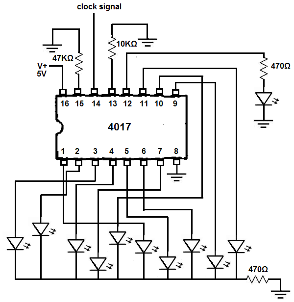
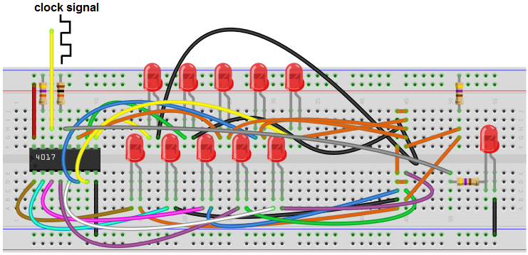
 A decade counter circuit operates by sequentially activating each of its output channels, one at a time, in a consecutive manner. For instance, if we construct a circuit featuring a decade counter along with 10 Light Emitting Diodes (LEDs), the decade counter will illuminate one LED at a time until all 10 LEDs are alight. This is the fundamental function of a decade counter. Essentially, it counts from one to ten, which aligns with its designation as a "decade" counter, signifying that it counts up to 10 (akin to a decade being comprised of 10 years). In this specific circuit, we will establish connections between 10 LEDs and our decade counter chip. The LEDs will activate individually, in sequence, until all of them are illuminated. Subsequently, the counter restarts the sequence, perpetually repeating this cycle. A decade counter is indeed an intriguing chip, owing to its versatility and the array of applications it accommodates. For this circuit, we will employ the widely used 4017 decade counter chip. A comprehensive description, encompassing its pin configuration, is provided below. Components Required: 4017 Decade Counter Chip 2 x 470 Ohm resistors 47 Kilohm resistor 10 Kilohm resistor 10 LEDs The 4017 is a readily available 16-pin integrated circuit, and it can be easily procured from various online distributors. A cost-effective source for this chip includes Jotrin Electronics, where you can also access a detailed guide via the following link: Jotrin Electronics - 4017 Decade Counter IC. The pinout for the 4017 is shown below. Out of the 16 pins on the 4017 chip, 10 are designated for output. These output pins are where we connect the components we want the chip to activate. In our case, we are using LEDs, with each LED attached to one of these output pins. The output pins are numbered from 0 to 9, and when the circuit is operational, they light up sequentially from 0 to 9. Two of the pins are used for power supply. V+ and GND are responsible for providing power to the 4017 chip. The chip operates at a 5V power supply. Therefore, we connect V+ to a 5V power source. The remaining pins include Reset, Clock, Enable, and Carry Out. Reset: This pin resets the count back to output 0. Normally, it is grounded, which means the reset function is inactive. When it is set to a HIGH voltage, it is triggered. So, if the circuit is in the process of counting up and reaches output 7, triggering the reset will take it back to output 0 once reset returns to a LOW state from a HIGH. Reset is active HIGH but is typically in a LOW state. Holding reset HIGH will keep the output at 0 and prevent the count from advancing. Clock: The clock is a crucial aspect of the 4017's operation. Without a clock signal, the 4017 chip remains idle. It progresses from one output to the next on the positive (rising) edge of a clock signal. As the clock transitions from LOW to HIGH, the 4017 chip commences and activates the next output. In essence, the chip's operation is synchronized with the clock signal. A faster clock signal results in quicker execution. If you're running the clock at 1Hz, the outputs will switch on with 1-second intervals. Increasing the clock speed to 5Hz means the intervals are now 200ms. At 5V, the maximum clock frequency is 2.5MHz, or 5.5MHz if you supply V+ with 15V. For this circuit, clock frequencies of about 1 to 10Hz are adequate for visual observation. Enable: The Enable pin is active low, which means it is typically connected to ground, rendering it active. When held LOW, the circuit counts up and operates. Setting this pin to HIGH halts all operation. Carry Out: The Carry Out pin goes HIGH once output 9 is reached and remains HIGH for outputs 0 to 4. It goes LOW for outputs 5 to 9. We can connect an LED to the Carry Out pin to observe this behavior. This covers all the pins' functionalities. The 4017 chip is quite straightforward and not challenging to understand or use. It's essential to note that only one output is active at any given time and turns off before the subsequent output activates. This sequence continues for all 10 outputs offered by the 4017 chip. So, when lighting up LEDs, all 10 LEDs illuminate one after the other until all have lit up. Then the decade counter resets, going from 0 to 9 again, repeating this process indefinitely. Its name, "decade counter," is due to its ability to count up to 10, from output 0 to output 9. 4017 Decade Counter Circuit The schematic diagram for the decade counter using the 4017 chip is shown below. Below is the breadboard layout for the circuit mentioned above. The initial step involves supplying power to the 4017 chip. Pin 16 of the chip receives a 5V input, while pin 8 is grounded. This action provides the necessary power for the chip to operate effectively. Subsequently, LEDs are connected to each of the outputs and the carryout pin. To prevent LED burnout, a 470Ω resistor is employed for the 10 LEDs connected to the outputs and the carryout pin. Both the reset and enable pins are kept at a LOW state during normal circuit operation. However, for testing purposes, these pins can be temporarily rewired from ground to the positive voltage rail to observe their impact. When the reset pin is briefly set to HIGH and then returned to a LOW state, the count resets to output 0 and then increments. Essentially, it restarts from the beginning. Setting the enable pin to HIGH will freeze the count. To enable this circuit to function correctly, a clock signal is essential. The most straightforward way to obtain this signal is by utilizing a function generator. With a function generator, you can effortlessly generate digital square wave signals and adjust the frequency as needed. In this scenario, we'd set it to 1Hz, which corresponds to one cycle per second. Consequently, there will be one low and one high signal per second. Consequently, you will witness a new LED lighting up every second. Afterward, you can fine-tune the frequency higher or lower. Increasing the frequency will accelerate the cycle. Consequently, the outputs will advance more rapidly, causing the LEDs to illuminate more quickly. Conversely, if you reduce the frequency to, say, 0.5Hz, the period (T) becomes T= 1/f= 1/0.5Hz= 2 seconds. As a result, there will be a 2-second interval between each LED activation. In the absence of a function generator, an alternative option is to construct a voltage-controlled oscillator to generate the clock signal. This can be achieved using a 4046 phase-locked loop chip, which, when correctly configured, produces digital square waves at pin 4. As a result, pin 4 of the VCO circuit should be connected to pin 14 of the 4017 chip. Upon activation, each LED should illuminate sequentially, commencing from output 0 and progressing up to output 9. This sequence repeats infinitely.
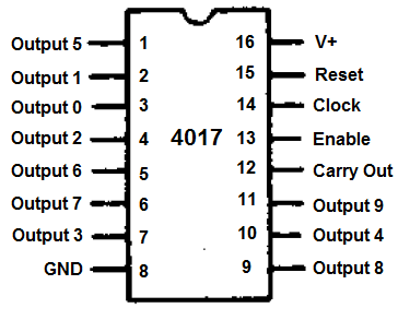
-
Infrared remote controllers are everywhere around us. The majority of home appliances are controlled using infrared remote controls. In this article/video, we learn to build a device that can decode (almost) any IR remote control and use the instructions to switch the relays (loads). So we can use this feature in a variety of applications without buying a new IR remote control and expensive hardware, such as turning ON/OFF the lights, opening/closing the curtains, ... etc. I have used an ATTiny85 microcontroller as the heart of the circuit. The device can record up to three IR codes in the EEPROM memory and switch 3 separate devices. Each relay can handle the currents up to 10A. The load switching mechanism (momentary ON/OFF, toggling, .. etc) can be programmed by the user. I used Altium Designer 21.4.1 and the SamacSys component libraries (SamacSys Altium Plugin) to design the Schematic and PCB. I also used the Siglent SDS2102X Plus/SDS1104X-E to analyze the IR signals. The device works stable and reacts well to the transmitted IR signals. So let’s get started and build this puppy! References Article: https://www.pcbway.com/blog/technology/Infrared_Remote_Control_Decoder___Switcher_Board.html [1]: L7805 datasheet: https://www.st.com/resource/en/datasheet/l78.pdf [2]: TS2937CW-5.0 datasheet: http://www.taiwansemi.com/products/datasheet/TS2937_E15.pdf [3]: VS1838 infrared receiver module datasheet: https://www.elecrow.com/download/Infrared%20receiver%20vs1838b.pdf [4]: FDN360P datasheet: https://www.onsemi.com/pdf/datasheet/fdn360p-d.pdf [5]: ATTiny85-20SUR datasheet: http://ww1.microchip.com/downloads/en/DeviceDoc/Atmel-2586-AVR-8-bit-Microcontroller-ATtiny25-ATtiny45-ATtiny85_Datasheet.pdf [6]: Si2302 datasheet: https://www.vishay.com/docs/63653/si2302dds.pdf [7]: Altium Designer electronic design CAD software: https://www.altium.com/altium-designer [8]: SamacSys Altium plugin: https://www.samacsys.com/altium-designer-library-instructions [9]: ATTiny85 schematic symbol, PCB footprint, 3D model: https://componentsearchengine.com/part-view/ATTINY85-20SUR/Microchip [10]: TS2937-5.0 schematic symbol, PCB footprint, 3D model: https://componentsearchengine.com/part-view/TS2937CW-5.0%20RP/Taiwan%20Semiconductor [11]: L7805 schematic symbol, PCB footprint, 3D model: https://componentsearchengine.com/part-view/L7805CV/STMicroelectronics [12]: SI2302 schematic symbol, PCB footprint, 3D model: https://componentsearchengine.com/part-view/SI2302DDS-T1-GE3/Vishay [13]: FDN360P schematic symbol, PCB footprint, 3D model: https://componentsearchengine.com/part-view/FDN360P/ON%20Semiconductor [14]: ATTinyCore: https://github.com/SpenceKonde/ATTinyCore [15]: IRRemote library: https://github.com/Arduino-IRremote/Arduino-IRremote [16]: Siglent SDS2102X Plus oscilloscope: https://siglentna.com/products/digital-oscilloscope/sds2000xp-series-digital-phosphor-oscilloscope [17]: Siglent SDS1104X-E oscilloscope: https://siglentna.com/digital-oscilloscopes/sds1000x-e-series-super-phosphor-oscilloscopes
-
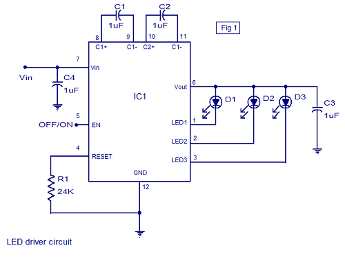
Circuit Diagram is given below: The circuit diagram of a three channel LED driver circuit using MAX7219 is shown below (Fig 1). C4 is an input filter capacitor. R1 is the resistor used for programming the output current. C3 is the output filter capacitor. C1 and C2 are the storage capacitors of the internal charge pump circuit. A logic high at pin 5 will enable the IC and a logic low on the same pin will drive the IC into shutdown mode. In the shutdown mode, the quiescent current is almost equal to zero. With the used value of R1, the LED current per channel will be 25mA. When powered up the MAX7219 operates in 1X mode i.e, the output voltage will be equal to the input voltage. If this output voltage is enough to regulate the current through all LEDs, the IC remains 1X mode. If the output voltage is not sufficient enough to regulate the desired current through the LEDs, the device automatically switches to the 1.5X mode where the output voltage is 1.5 times the input voltage. This process is repeated when ever the IC is powered up or awaken from shutdown mode. Can this circuit work? Actually,the LED driver in this circuit is CAT3063,however,I can't found this mode. I would like to use MAX7219 instead of CAT3063. Please give me some help! Appreciating!
-
I want to charge a LiPo battery via the ballance plugs. So it's a ballanced charge, and I don't run into any problems, day in and day out.The light can be very small, but I want it to be bright. So even using a couple LEDs would make a really nice and bright mailbox light.I want the light to last all night long. So that means I need to know the current draw of the LEDs to the capacity of the LiPo batteries.etc.I need help on this. I need help with the fact how to use an Op Amp to shut the light off when it's daylight out.. or a specific amount of light is sensed.Light Sensed : Start charging, and turn off the LED lights.Light Sensed : Set the Op Amp to detect 4.2vdc. When it does, shut down the charging, &LED's stay off until darkness is detected.That's my idea of a mailbox light, with very long battery life, and high current solar charging abilities.Can anyone help me with this kind of circuit? Here is where my LED come from http://www.kynix.com/Search/led.html
-
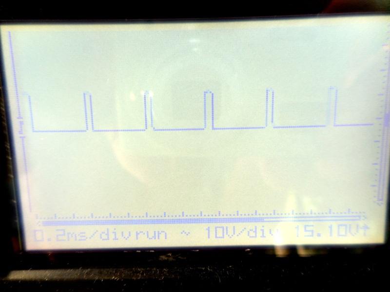
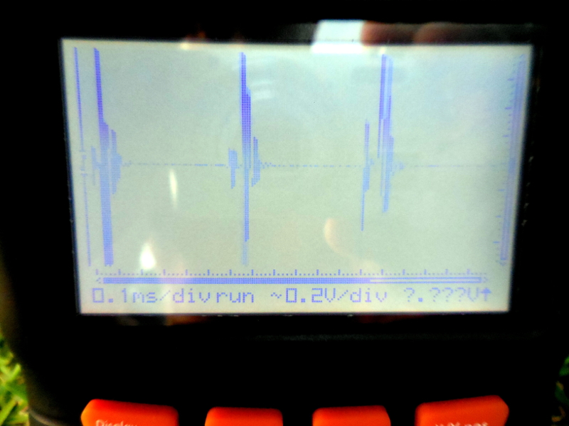
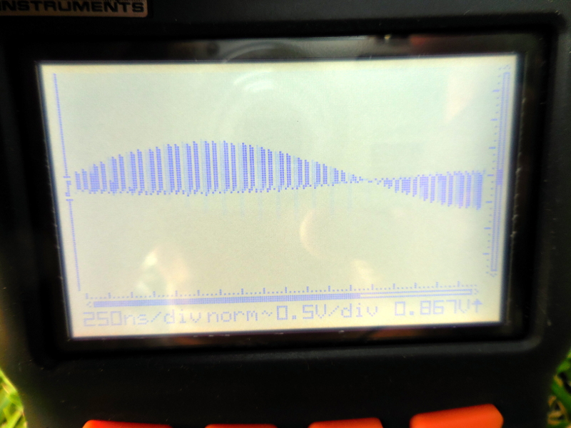
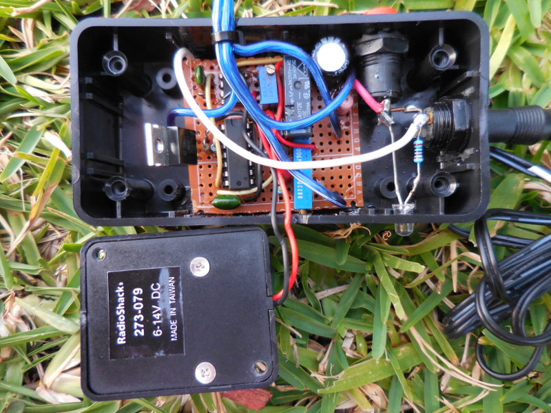
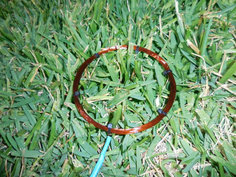
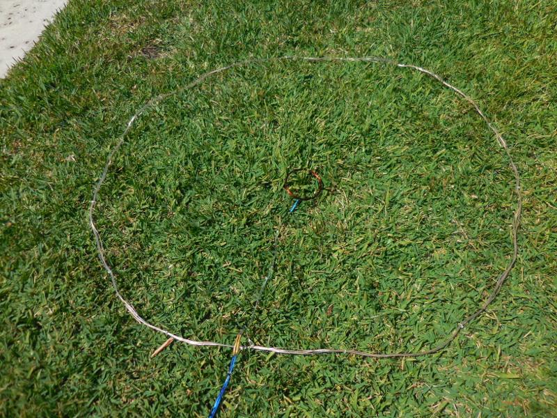
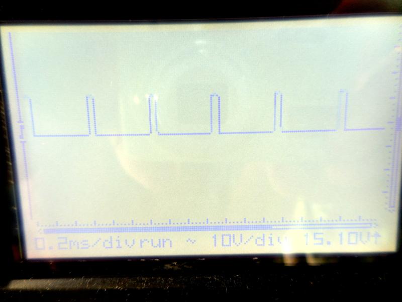
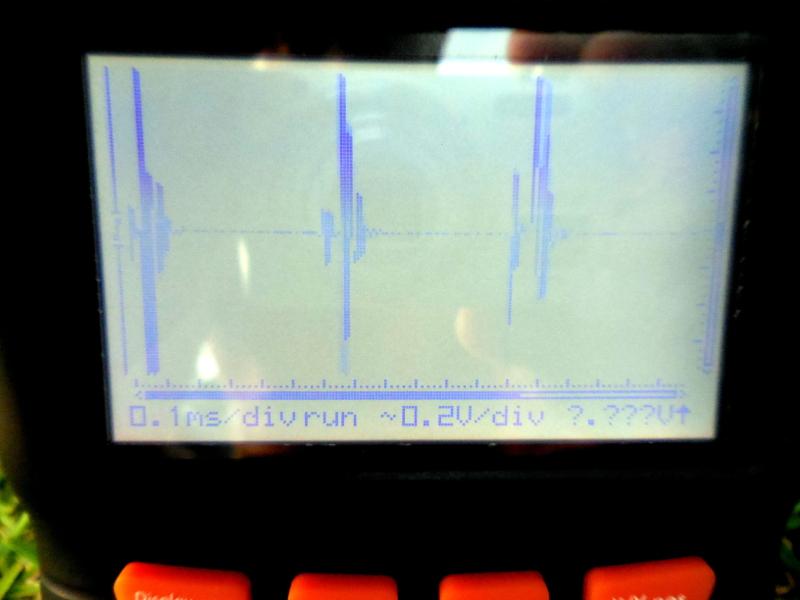
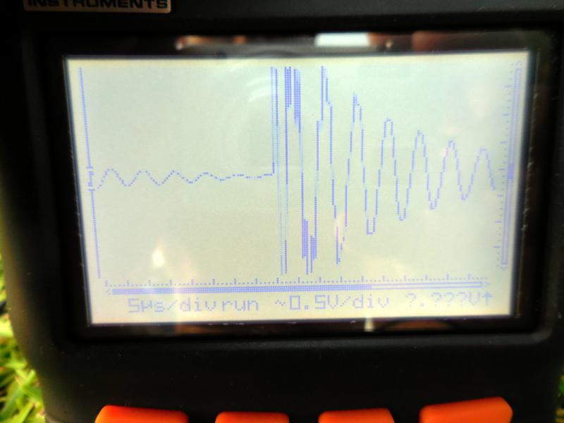
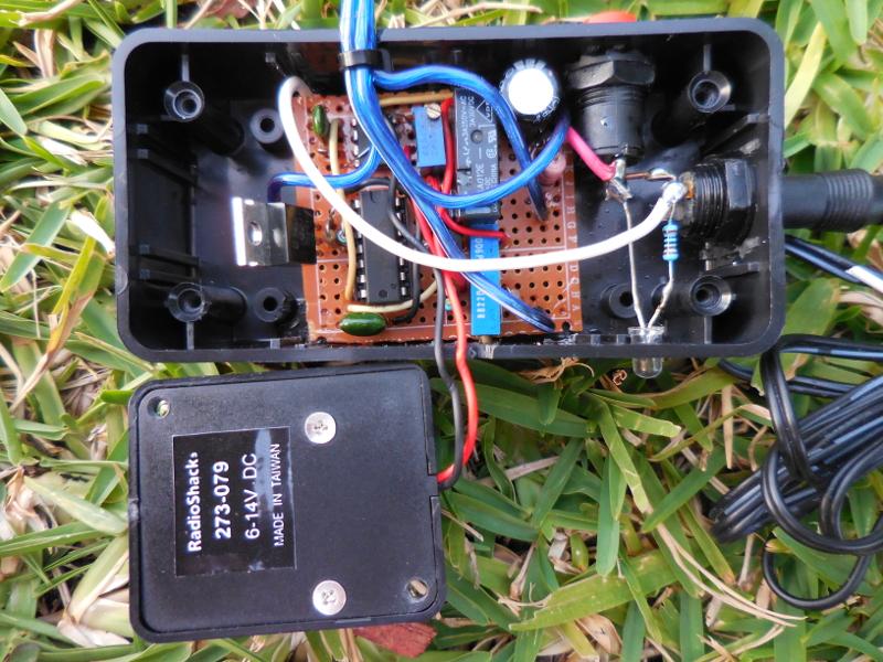
Hello. I made this circuit below: http://www.diy-electronic-projects.com/p270-Everything-that-moves-ALARM The circuit does not appear to be working properly, and I would like to get it working. To be honest with you, I never heard of a human body detector using eddy currents. The first image shows the pulses on the gate of the mosfet. They appear to be low duty cycle(around 15-20%). The other images show the pulses received by the smaller coil(5"/100T/26ga enamel wire) placed in the center of the 24ga speaker wire/5 foot diameter (5T) TX loop. The circuit can be set, but you cannot get it to trigger unless you actually touch/move the RX coil.The RX signal on the scope is more or less sinusoidal. Operating voltage is around 13.5vdc. Hopefully you can assist me. There is a 1000uF electrolytic capacitor across the power rail. Pins 4/8 on the cmos 555 and pin #14 of the 4093 are connected together to the + rail. Thanks,Doug

-
This simple, one-transistor amplifier provides a voltage gain over 1000 (60 dB) for driving a high impedance ceramic (crystal) earphone. The high gain is achieved by replacing the traditional collector resistor with an unusual constant-current diode that supplies 1/2 mA yet exhibits a very high resistance to the audio. This amplifier will give excellent battery life, drawing only 500 uA. Below is a typical application using it with the first crystal radio circuit. The amplifier provides good volume with a modest antenna. You may want a volume control as with the TL431 project! Or use the Crystal Radio RF Amplifier directly above for even more sensitivity with less than 2 mA current drain.