Search the Community
Showing results for tags 'dht11'.
Found 4 results
-
 This project will allow you to monitor environmental conditions in your home automation setup. Here are the steps to achieve this: Integrating DHT11 with Beetle ESP32 C3 and Home Assistant 1. Components Required Before we begin, gather the necessary components: BeetleESP32C3 development board DHT11 temperature and humidity sensor Jumper wires USB cable for programming A computer with the Arduino IDE or ESPHome installed Get PCBs for Your Projects Manufactured You must check out PCBWAY for ordering PCBs online for cheap! You get 10 good-quality PCBs manufactured and shipped to your doorstep for cheap. You will also get a discount on shipping on your first order. Upload your Gerber files onto PCBWAY to get them manufactured with good quality and quick turnaround time. PCBWay now could provide a complete product solution, from design to enclosure production. Check out their online Gerber viewer function. With reward points, you can get free stuff from their gift shop. Also, check out this useful blog on PCBWay Plugin for KiCad from here. Using this plugin, you can directly order PCBs in just one click after completing your design in KiCad. 2. Flashing ESPHome to Beetle ESP32 C3 Install ESPHome on your computer. You can follow the instructions in my previous blog. Create an ESPHome configuration file (e.g., dht11.yaml) with the following content: sensor: - platform: dht pin: 0 model: dht11 temperature: name: "Living Room Temperature" humidity: name: "Living Room Humidity" update_interval: 5 s Replace placeholders (YourWiFiSSID, YourWiFiPassword, etc.) with your actual values. Compile and upload the configuration to your Beetle ESP32 C3 using the ESPHome CLI. 3. Integrating with Home Assistant Open Home Assistant. Click on Configuration (bottom left) and go to Integrations. Click the + button and select ESPHome. Enter the IP address of your ESP32 (leave the port as 6053) and click Finish. 4. Viewing Temperature and Humidity Once integrated, Home Assistant will discover the Beetle ESP32 C3 module and create entities for temperature and humidity. You can access these entities in Home Assistant’s dashboard and display them as cards or graphs. And that’s it! You’ve successfully integrated the DHT11 sensor with your Beetle ESP32 C3 and Home Assistant. Feel free to customize and expand this project based on your needs. Happy monitoring! 🌡️💧🏠
 -
 Had some time this weekend and a desire to create something new and interesting, so went ahead and created an Arduino/NodeMCU based indoor dial thermometer. This device displays the temperature in degree centigrade on a D-Shaped Gauge as well as on a 7-Segment display. In addition to that, it also saves the temperature and humidity readings in a MySQL DataBase hosted on a home based Raspberry Pi Server. The data is then displayed using the "Our Smart Home" app. Awards This project got featured on Cults3D and Instructables https://cults3d.com/en/3d-model/gadget/arduino-based-indoor-dial-thermometer https://www.instructables.com/NodeMCU-Based-3D-Printed-Indoor-Gauge-Thermometer/ Components Required For this project we need: 2 x TM1637 Display Modules 1 x DHT22 or DHT11 Module 1 x NodeMCU Microcontroller 1 x 28BYJ-48 Stepper Motor with ULN2003 Driver Board 1 x 10K Resistor A 3D Printer Copper Wire and Some Nuts & Bolts Circuit Diagram The circuit is very simple. Connect the ULN2003 driver board’s IN1, IN2, IN3 and IN4 to the NodeMCUs digital pins D0, D1, D2 and D3. Then connect the OUT Pin of the DHT22 to the D5 Pin of NodeMCU. After that connect the 2 x Display Modules to the microcontroller. We are going to use a Common Clock Pin D4 for both modules. Then connect the DIO of one of the modules to D6 (TEMP) and the other one to D7 (HUM) pins on the NodeMCU. Important: Please avoid using the boot config pins D3, D4, D8 and the RTC pin D0 for the displays. Now, on the D8 Pin we are going to connect the switch. This switch has a very important role in this circuit. This switch acts as the 'home' or the 'starting point' of the stepper motor. When the switch is open Pin D8 is connected to GND through the pull-down resistor and we read a LOW. When the switch is closed, Pin D8 connects to 3.3v pin of NodeMCU and we read a HIGH. When the 'temperature changes' or the 'device boots up', the pointer starts moving 'counterclockwise'. As soon as the pointer hits the home position, Pin D8 reads HIGH and the logic moves the pointer 'clockwise' to display the temperature on the gauge as read by the DHT22 module. The Code The code starts by including all the necessary libraries. Then it defines all the variables needed for setting up the WiFi connection. Next, it assigns a static IP address to the ESP8266 (if you want to use DHCP then go ahead and delete these three lines from the code). After that, it sets up the 2 x URLs that are needed for updating the heartbeat, temperature and humidity. String URLUpdateStatus = "http://192.168.0.7/Arduino/Weather/UpdateStatus.php"; String URLUpdateTemp = "http://192.168.0.7/Arduino/Weather/UpdateTemperature.php"; Before going ahead let's have a quick look at the 2 php files. The "UpdateStutus.php" file uses an UPDATE query to update the timestamp of the device sending the request to the current epoch time and hence updating the heartbeat. <?PHP try { $Token = $_GET["Token"]; $Location = $_GET["Location"]; include "ConnectionStringArduino.php"; // Create connection $sql = 'Update `Status` SET `DateTime`=\''.time().'\',`State`=\'1\' WHERE `Device`=\''.$Location.'\' AND `Token` = \''.$Token.'\';'; $result = $con->query( $sql ); if($result === FALSE) { die(mysqli_error());} mysqli_close($con); } catch (Exception $e) {} ?> The "UpdateTemperature.php" uses an INSERT query to add a new row to the database with the current values of Temperature and Humidity. <?PHP try { $Location = $_GET["Location"]; $TEMP = $_GET["TEMP"]; $HUM = $_GET["HUM"]; include "ConnectionStringArduino.php"; // Create connection $sql = "INSERT INTO `Weather` (`DateTime`,`Temperature`,`Humidity`,`Location`) VALUES ('".time()."','".$TEMP."','".$HUM."','".$Location."');"; $result = $con->query( $sql ); if($result === FALSE) { die(mysqli_error());} mysqli_close($con); } catch (Exception $e) {} ?> This is what is written to the database and can be displayed using Google Charts, in my case, I am using the "Our Smart Home" app to display the data using php and JavaScript. Currently I am only displaying the data from the Study room and the Peg Box. To know more about my award winning "Peg Box" project please have a look at my electronics tutorial no. 34 "Peg Box with Temperature and Humidity Monitor using NodeMCU" (https://youtu.be/elH331NXPsU). After that, I am defining all the variables required for reading and storing the value of temperature and humidity. Next, I am defining all the variables and setting up any additional symbols required for displaying temperature and humidity on the TM1637 Display Module. After that, I am defining the D8 pin of the NodeMCU as the reset switch pin. We will talk about this in detail in the following sections. Next, I am setting up the Steps Per Revolution of the stepper motor as 2038 and then initializing the stepper library through pins D0 to D3. const int stepsPerRevolution = 2038; // Change this to fit the number of steps per revolution of your motor Stepper myStepper(stepsPerRevolution, D0, D2, D1, D3);// Initialize the stepper library on pins D0 through D3 One thing to note: since I need both clockwise and counterclockwise movements, I have to initialize the pins in the order shown on screen. Then in the setup() section, first I am setting up the WiFi connection and then sending a heartbeat to the server. Then I am setting up the brightness of the 7-Segments to their max values followed by starting the dht module and finally setting the pin-mode of the switch to INPUT. void setup() { Serial.begin(115200); // Initialize the serial port /*********** Setup a WiFi connection ***********/ if (WiFi.config(local_IP, gateway, subnet)) { Serial.println("Static IP Configured"); } else { Serial.println("Static IP Configuration Failed"); }; WiFi.mode(WIFI_STA); WiFi.begin(WIFI_SSID, WIFI_PWD); while (WiFi.status() != WL_CONNECTED) { delay(500); Serial.print("."); }; Serial.println("\nWiFi connected"); Serial.print("IP address: "); Serial.println(WiFi.localIP()); SendIamAlive(); // Send the initial wakeup message to the server /**********************************************/ display_TMP.setBrightness(7); // Set the display brightness (0-7) display_HUM.setBrightness(7); // Set the display brightness (0-7) dht.begin(); // Setup the DHT sensor pinMode(SWITCH, INPUT); // Declare the switch pin as input }; Now, in the loop() section I am reading the temperature using the Read_Temp() function and then sending the Temperature and Humidity values every 30 minutes and heartbeat every minute to the home server. void loop() { /** Read the temp and humidity info from ther sensor and display it on the 7-segmnet and Gauge **/ Read_Temp(); /** Sending Humidity and temperature every 30 minutes **/ if((millis() - lastTime) > timerDelay){ Serial.println("Sending Temp and Humidity");SendTemperatureAndHumidity(); lastTime = millis(); }; /** Sending I am alive message every minute **/ if((millis() - StatusCounter) > 60000){ Serial.println("Sending Heartbeat"); SendIamAlive(); StatusCounter = millis(); }; }; Next, you see the definition of the SendIamAlive() and SendTemperatureAndHumidity() functions which utilizes the WiFiConnect() function to send the values using the previously discussed URLs. The Read_Temp() function reads the temperature and humidity and updates the 7-Segment displays and moves the pointer only if there is a change in the values. The Move_Needle() function first sends the pointer to the home position using the Return_Home() function and then looks through and moves the pointer to the correct position until the stepCout is = STEPS. The value of STEPS is calculated based on the "stepsPerRevolution" which we previously set it up as 2038. So, 2038 / 2 (for half circle) = 1019 Now by dividing 1019 by 180 degrees we get the steps required to display each degree centigrade. Now to display each degree centigrade we need 180/60 = 3 divisions. Since our gauge starts from -10 and not 0 we also have to add the first 10 blocks which is (5.661 * 10 * 3) to our calculation. int STEPS = (5.661 * 3 * TEMP) + 169.833; // 5.661 (step resolution) * 3 (steps to display each °C) * TEMP + 169.833 (5.661 * 10 * 3) = since it starts from -10 and not 0) That's it as easy as that. 3D Designing Lets have a quick look at the 3D model of the project. At the front, we have The Pointer, D-Shaped Dial, and the Temperature Scale on the dial. Down at the bottom we have the Enclosure that will house the microcontroller and all other electronics components in it. The enclosure has a Lid to keep the electronic components safe and sound. At the back, we have a pocket to hold the DHT22 Module, 3 x holes for the stepper motor, 2 x groves for the TM1637 Display Module and 2 x L-Shaped Brackets to hold the top Dial to the bottom Enclosure. 3D Printing Once the 3D models were sorted, it was time for me to fire up my 3D printing oven and start printing these 3D models. I used: - 1.75mm Cold White PLA Filament, and printed the models with - 0.2mm - with 0% infill - and with support. As we all know, 3D printing is the process that uses computer-aided design or CAD, to create objects layer by layer. 3D printing is not a new technology, it's been there since the 1980's, when Charles W. Hull invented the process and created the first 3D-printed part. Since then, the field of 3D printing has grown exponentially and holds countless possibilities. The 3D printing process fascinates me a lot and I sometimes love to sit near my printer and watch these layers getting printed. The entire printing process took a little over 5 hours to complete and this is the final result. Alright now, let's start gluing all the printed parts. I first superglued the L-Shaped Brackets to the dial followed by the pocket that will hold the DHT22 module. Then, I went ahead and screwed the bottom enclosure to the top section via the L-Shaped Brackets. Breadboard Demo Before adding the electronic bits to the 3D printed bits, let's do a quick test to make sure everything works as expected. So, this 7-Segment display is displaying the temperature and the other one is displaying the humidity. The needle is currently going round and round in circles as it has no idea where to stop. To stop the needle, and to send it the correct position on the gauge, I need to connect this red jumper cable connected to 3.3v to the D8 Pin of the NodeMCU. Once I short the cable, the needle changes its direction and moves clockwise to display the temperature value read from the DHT22 module. The temperature and humidity values are also sent to the 'Home Server' which are then displayed using the "Our Smart Home" app. Coloring Using Acrylic colors, I painted all the 3D printed parts of the project. Assembling Once the coloring is done, its now time for me to put all the electronic components together. First I screwed the stepper motor to the back of the dial. Then, I gently pushed the DHT22 Module into its pocket at the back of the dial. Now the interesting bit. As per our previous discussion, we are going to use a copper wire as a switch that will move the pointer to its correct position. The copper wire will be fed through these two holes from the back and will loop through this small pipe like structure in the front. A small cut will be made on the top exposed side of the copper wire. Now on the pointer, we need to add a small piece of copper wire. When this copper bit touches the two copper wires on the pipe, it will complete the circuit and will send a HIGH to the system. Next, I am hot gluing the two TM1637 7-Segment Display Modules to the back of the dial. Once done, it's pretty much just a matter of soldering all the sensors to the NodeMCU as per our circuit diagram. Final Demo So, this is how my final setup looks like. Once the device is turned on, the pointer moves counterclockwise until it touches the copper wires that acts like a switch. Upon touching the wires the pointer moves clockwise to display the temperature value read from the DHT22 module on the D-Shaped Gauge. The temperature and humidity values are also displayed using 7-Segment Displays. The values are also sent over WiFi to a Raspberry Pi Home Server and stored in a MySQL database. Using google charts, you can display the data using various different graph options. In my case, I am using the "Our Smart Home" app to display the data using php and JavaScript. Thanks for watching, please comment and let me know if there are any scopes of improvement. Thanks Thanks again for checking my post. I hope it helps you. If you want to support me subscribe to my YouTube Channel: https://www.youtube.com/user/tarantula3 Video: Watch Full Blog Post: Visit Thermometer STLs: Download Peg Box: Watch How To Wire A Pushbutton: View Stepper Motor Specs: View Support My Work BTC: 1Hrr83W2zu2hmDcmYqZMhgPQ71oLj5b7v5 LTC: LPh69qxUqaHKYuFPJVJsNQjpBHWK7hZ9TZ DOGE: DEU2Wz3TK95119HMNZv2kpU7PkWbGNs9K3 ETH: 0xD64fb51C74E0206cB6702aB922C765c68B97dCD4 BAT: 0x9D9E77cA360b53cD89cc01dC37A5314C0113FFc3 LBC: bZ8ANEJFsd2MNFfpoxBhtFNPboh7PmD7M2 COS: bnb136ns6lfw4zs5hg4n85vdthaad7hq5m4gtkgf23 Memo: 572187879 BNB: 0xD64fb51C74E0206cB6702aB922C765c68B97dCD4 MATIC: 0xD64fb51C74E0206cB6702aB922C765c68B97dCD4 Thanks, ca gain in my next tutorial.
 -
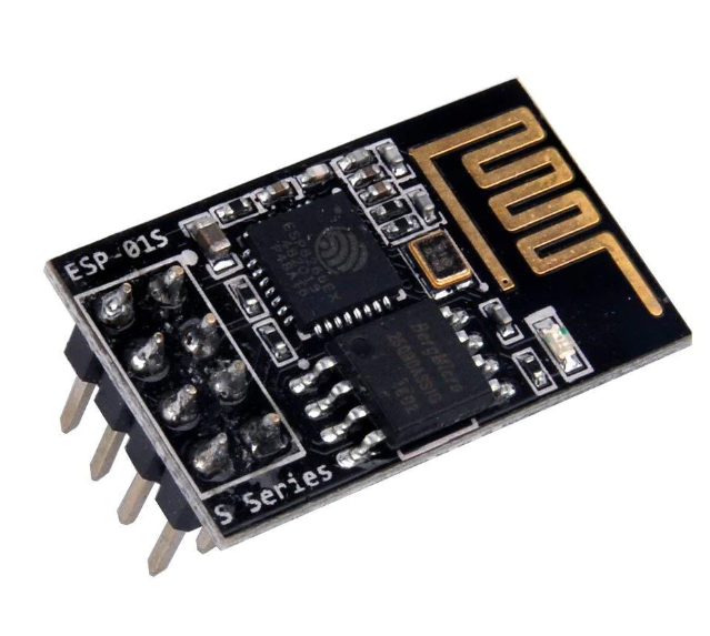
Introduction: The ESP-01 is a popular and versatile Wi-Fi module that can be easily programmed and interfaced with various sensors. In this project, we will use the ESP-01 along with the DHT11 temperature and humidity sensor to create a simple weather station. We will measure temperature and humidity readings and display them on a web server hosted by the ESP-01. Materials Required: ESP-01 module DHT11 temperature and humidity sensor USB to TTL converter Breadboard and jumper wires 3.3V power supply Arduino IDE and ESP8266 board support package Circuit Diagram: Steps: Setting up Arduino IDE: Open Arduino IDE and go to File > Preferences. Add the following URL to the Additional Board Manager URLs: http://arduino.esp8266.com/stable/package_esp8266com_index.json Go to Tools > Board > Boards Manager, search for "ESP8266" and install the package. Connecting ESP-01: Connect the ESP-01 to the USB to TTL converter as follows: ESP-01 VCC to 3.3V, GND to GND, TX to RX, and RX to TX. Enable GPIO0 and GPIO2 by connecting them to VCC with a 10k resistor. Connect the DHT11 sensor to the ESP-01 as follows: DHT11 VCC to 3.3V, GND to GND, and data pin to GPIO2. Coding: Open Arduino IDE and select the ESP8266 board from Tools > Board menu. Use the following code to read temperature and humidity from the DHT11 sensor and host a web server to display the readings: #include <ESP8266WiFi.h> #include <ESP8266WebServer.h> #include <DHT.h> const char* ssid = "your-ssid"; const char* password = "your-password"; DHT dht(2, DHT11); ESP8266WebServer server(80); void handleRoot() { float temperature = dht.readTemperature(); float humidity = dht.readHumidity(); String message = "Temperature: " + String(temperature) + "°C\nHumidity: " + String(humidity) + "%"; server.send(200, "text/plain", message); } void setup() { Serial.begin(115200); WiFi.begin(ssid, password); while (WiFi.status() != WL_CONNECTED) { delay(1000); Serial.println("Connecting to WiFi..."); } Serial.println("WiFi connected"); dht.begin(); server.on("/", handleRoot); server.begin(); Serial.println("Web server started"); } void loop() { server.handleClient(); } Replace your-ssid and your-password with your Wi-Fi network credentials. Testing: Upload the code to the ESP-01. Open the serial monitor to view the ESP-01's IP address. Enter the IP address in a web browser to see the temperature and humidity readings. Conclusion In this project, we successfully built a weather station using the ESP-01 and DHT11 sensor. This project can be further expanded by adding more sensors or incorporating data logging capabilities. The ESP-01's flexibility and ease of use make it an ideal choice for IoT projects.
-
Story A NeoPixel ring controlled by a DHT11 sensor and an Arduino Nano can be a fascinating project that combines temperature sensing with visual feedback. This article will guide you through the process of building such a system. Materials Needed Arduino Nano DHT11 Temperature and Humidity Sensor Neo Pixel Ring Jumper Wires Get PCBs For Your Projects Manufactured You must check out PCBWAY for ordering PCBs online for cheap! You get 10 good-quality PCBs manufactured and shipped to your doorstep for cheap. You will also get a discount on shipping on your first order. Upload your Gerber files onto PCBWAY to get them manufactured with good quality and quick turnaround time. PCBWay now could provide a complete product solution, from design to enclosure production. Check out their online Gerber viewer function. With reward points, you can get free stuff from their gift shop. Also, check out this useful blog on PCBWay Plugin for KiCad from here. Using this plugin, you can directly order PCBs in just one click after completing your design in KiCad. Step 1: Connecting the Hardware First, connect the DHT11 sensor and the Neo Pixel ring to the Arduino Nano. The DHT11 sensor can be connected to any digital pin on the Arduino Nano. The Neo Pixel ring should be connected to the D2 pin of the Arduino Nano. Step 2: Installing the Libraries You will need to install the DHT library and the Adafruit Neo Pixel library in your Arduino IDE. These libraries contain the necessary functions to interact with the DHT11 sensor and the Neo Pixel ring. First Navigate to Sketch > Include Library > Manage Libraries... In the Library Manager, there is a search box. Type “DHT sensor library” into the search box. In the search results, find the library named “DHT sensor library” by Adafruit. Click on it, then click the “Install” button. And that’s it! You’ve successfully installed the DHT11 sensor library in Arduino IDE. This library should now be available for inclusion in your sketches. Step 3: Programming the Arduino The next step is to program the Arduino Nano. The program should read the temperature from the DHT11 sensor and change the color of the Neo Pixel ring based on the temperature. For example, you could program the Neo Pixel ring to display a blue color when the temperature is below a certain threshold. A green color when the temperature is within a comfortable range, and a red color when the temperature is above a certain threshold. Step 4: Testing the System After programming the Arduino Nano, it’s time to test the system. Power up the Arduino and observe the color of the Neo Pixel ring. Try changing the temperature around the DHT11 sensor (for example, by blowing hot or cold air onto the sensor) and see if the color of the Neo Pixel ring changes accordingly. #include <Adafruit_NeoPixel.h> #include <Adafruit_Sensor.h> #include <DHT.h> #include <DHT_U.h> #define DHTTYPE DHT11 // DHT 11 #define DHTPIN 3 DHT_Unified dht(DHTPIN, DHTTYPE); #define PIN 2 // Neo Adafruit_NeoPixel strip = Adafruit_NeoPixel(8, PIN, NEO_GRB + NEO_KHZ800); void setup() { Serial.begin(115200); dht.begin(); sensor_t sensor; strip.begin(); strip.setBrightness(100); strip.show(); } void loop() { sensors_event_t event; dht.temperature().getEvent(&event); Serial.print(F("Temperature: ")); float temp1 = event.temperature; Serial.print(temp1); Serial.println(F("°C")); dht.humidity().getEvent(&event); Serial.print(F("Humidity: ")); float hum1 = event.relative_humidity; Serial.print(hum1); Serial.println(F("%")); if (temp1 >= 28 && temp1 < 31) { strip.clear(); // Set all pixel colors to 'off' for (int i = 0; i < 12; i++) { // For each pixel... strip.setPixelColor(i, strip.Color(0, 150, 0)); strip.show(); } } else if (temp1 < 28) { strip.clear(); for (int i = 0; i < 12; i++) { // For each pixel... strip.setPixelColor(i, strip.Color(0, 0, 150)); strip.show(); } } else { strip.clear(); for (int i = 0; i < 12; i++) { // For each pixel... strip.setPixelColor(i, strip.Color(150, 0, 0)); strip.show(); } } } Conclusion Building a DHT11-controlled Neo Pixel ring with an Arduino Nano is a fun and educational project combining temperature sensing and visual feedback. With this system, you can visually monitor the temperature in a room and get a sense of whether the temperature is within a comfortable range.