Search the Community
Showing results for tags 'raspberry pi'.
Found 24 results
-
 With the possibility of 3D hardware graphic acceleration on Raspberry Pi, it becomes much easier to play great PC Games on RPi. Thanks to OpenGL and new ExaGear emulator feature. Learn more from the article above.
 -
 How to Track the ISS Location with Node-RED Node-RED is a visual programming tool that allows you to create flows of data and logic using nodes. In this article, we will use Node-RED to track the location of the International Space Station (ISS) and display it on a world map. What You Need To follow this tutorial, you will need the following: A computer with Node-RED installed. You can download and install Node-RED from here. An internet connection to access the ISS location API and the world map node. Two Node-RED nodes: node-red-contrib-iss-location and node-red-contrib-web-worldmap. You can install them from the Node-RED palette or by running the following commands in your Node-RED user directory, typically ~/.node-red: npm install node-red-contrib-web-worldmap Get PCBs for Your Projects Manufactured You must check out PCBWAY for ordering PCBs online for cheap! You get 10 good-quality PCBs manufactured and shipped to your doorstep for cheap. You will also get a discount on shipping on your first order. Upload your Gerber files onto PCBWAY to get them manufactured with good quality and quick turnaround time. PCBWay now could provide a complete product solution, from design to enclosure production. Check out their online Gerber viewer function. With reward points, you can get free stuff from their gift shop. Also, check out this useful blog on PCBWay Plugin for KiCad from here. Using this plugin, you can directly order PCBs in just one click after completing your design in KiCad. The Flow The flow we will create consists of four nodes: An inject node that triggers the flow every 10 seconds. An HTTP-request node that queries the ISS location API and returns the current latitude and longitude of the ISS. A function node that formats the location data into a message object that the world map node can use. A worldmap node that displays a world map and a marker for the ISS location. The flow looks like this: The Nodes Let’s take a closer look at each node and how to configure them. The Inject Node The inject node is used to trigger the flow at regular intervals. To configure it, double-click on it and set the following properties: Name: Every 10 seconds Repeat: interval Every: 10 seconds This will make the node send a timestamp message every 10 seconds. The HTTP Request Node The ISS location node is used to query the ISS location API and return the current latitude and longitude of the ISS. To configure it, double-click on it and set the following properties: Name: ISS Location URL: api.open-notify.org/iss-now.json This will make the node send a message object with the following properties: This node will return the following payload: the return payload contains thefollowing properties: latitude: a string indicating the current latitude of the ISS in degrees. longitude: a string indicating the current longitude of the ISS in degrees. The Function Node The function node is used to format the location data into a message object that the world map node can use. To configure it, double-click on the JSON node and set the following properties. Next, set the following properties on the change node: This will make the node send a message object with the same properties as the original message, except for the payload, which will be an object suitable for the world map node. Here is the final transformed payload that the map node can understand. The World Map Node The world map node displays a world map and a marker for the ISS location. To configure it, double-click on it and set the following properties: This will make the node display a world map widget on the dashboard, with various options to customize the view. The node will also listen for incoming messages with location data and display a marker on the map accordingly. The Result To see the result, deploy the flow and open the dashboard. You should see a world map with a blue globe icon indicating the current location of the ISS. The icon will move as the ISS orbits the Earth. You can also click on the icon to see the name and the coordinates of the ISS. Conclusion In this article, we have learned how to use Node-RED to track the location of the ISS and display it on a world map. We have used node-red-contrib-web-worldmap to query the ISS location API and display the map widget. We have also used a function node to format the location data into a message object that the world map node can use. We hope you have enjoyed this tutorial and learned something new. If you want to learn more about Node-RED and its nodes, you can check out these web pages: Node-RED node-red-contrib-iss-location (node) - Node-RED node-red-contrib-web-worldmap (node) - Node-RED Happy coding!
 -
Telegram is a popular messaging app that offers end-to-end encryption, cloud-based storage, and a variety of features for communication. One of these features is the ability to create and interact with bots, which are automated programs that can perform tasks or provide information. In this blog post, I will show you how to use Telegram bots to control your home automation system with Node-RED, a visual programming tool that allows you to connect and orchestrate devices, services, and APIs. Get PCBs For Your Projects Manufactured You must check out PCBWAY for ordering PCBs online for cheap! You get 10 good-quality PCBs manufactured and shipped to your doorstep for cheap. You will also get a discount on shipping on your first order. Upload your Gerber files onto PCBWAY to get them manufactured with good quality and quick turnaround time. PCBWay now could provide a complete product solution, from design to enclosure production. Check out their online Gerber viewer function. With reward points, you can get free stuff from their gift shop. Also, check out this useful blog on PCBWay Plugin for KiCad from here. Using this plugin, you can directly order PCBs in just one click after completing your design in KiCad. 1. What You Need: To follow this tutorial, you will need: A Telegram account and a smartphone with the Telegram app installed. A Node-RED instance running on a device that can access your home automation system. You can use a Raspberry Pi, a computer, or a cloud service. For more information on how to install and run Node-RED, see here. The node-red-contrib-telegrambot node provides Telegram bot nodes for Node-RED. You can install it from the Node-RED palette manager or by running the following command in your Node-RED directory: npm install node-red-contrib-telegrambot A Telegram bot token is a unique identifier for your bot. You can create a bot and get its token by talking to the @BotFather bot on Telegram. For more details. A chat ID is a unique identifier for the chat between you and your bot. You can get your chat ID by sending a message to your bot. 2. How It Works: The basic idea is to use Node-RED to create a flow that receives messages from your Telegram bot, parses them to extract commands or queries, and then sends commands or responses back to your bot. The node-red-contrib-telegrambot node provides two main nodes for this purpose: the receiver node and the sender node. The receiver node listens for messages from your bot and outputs a message object with the following properties: msg.payload.chatId: The chat ID of the sender. msg.payload.type: The type of the message, such as “message”, “photo”, “location”, etc. msg.payload.content: The content of the message, such as a text string, a file ID, or an object with additional data. The sender node takes a message object as input and sends it to your bot. The message object should have the following properties: msg.payload.chatId: The chat ID of the recipient. msg.payload.type: The type of the message, such as “message”, “photo”, “location”, etc. msg.payload.content: The content of the message, such as a text string, a file ID, or an object with additional data. You can use other nodes in between the receiver and sender nodes to process the messages and perform actions on your home automation system. For example, you can use a switch node to route messages based on their type or content, a function node to write custom logic in JavaScript, or an HTTP request node to call external APIs. 3. A little recap of the previous blog: In the previous blog, we have seen how to use the telegram bot with node-red to trigger the temperature data. In this blog, we are going to see how to automate and trigger the Telegram bot to control the GPIO. 4. Telegram to Node-Red: In the last article, we have seen how to trigger the sensor readings from Node-Red to Telegram, now let's see how to trigger and get the sensor data from Telegram Bot. First, we need to use the telegram receiver node. And configure the node with your bot credentials. Then add a debug block. Next, just try to send some messages to your bot and look at the response in the debug console. Now, you can see your texts are coming under payload.content. So, we are going to filter the content then based on the content we are going to trigger the actions. Here are my complete blocks. In this, I have tried to filter the contents as Green, Red, Blue, Off, and Env. Based on the contents we are going to trigger the neo pixels with certain colors. Finally, just deploy the flow, open the telegram bot, and test out the connections. Let's try out the neo pixels. [ { "id": "eb8f9c0d054be30c", "type": "tab", "label": "Flow 2", "disabled": false, "info": "", "env": [] }, { "id": "ea63aa67.c972f", "type": "template", "z": "eb8f9c0d054be30c", "name": "", "field": "payload", "fieldType": "msg", "format": "handlebars", "syntax": "mustache", "template": "{\"chatId\": 5379039379,\n\"type\":\"message\",\n\"content\":\"Temperature : {{payload}}, Humidity : {{humidity}}\"}", "output": "json", "x": 660, "y": 360, "wires": [ [ "9e00d0a7.d5ccf", "600063bd96d765e6" ] ] }, { "id": "9e00d0a7.d5ccf", "type": "debug", "z": "eb8f9c0d054be30c", "name": "", "active": true, "tosidebar": true, "console": false, "tostatus": false, "complete": "payload", "targetType": "msg", "statusVal": "", "statusType": "auto", "x": 830, "y": 300, "wires": [] }, { "id": "600063bd96d765e6", "type": "telegram sender", "z": "eb8f9c0d054be30c", "name": "roboerto_bot", "bot": "ae1a60539b8e5308", "haserroroutput": true, "outputs": 2, "x": 830, "y": 380, "wires": [ [], [] ] }, { "id": "f2f9819ae972ae60", "type": "rpi-dht22", "z": "eb8f9c0d054be30c", "name": "", "topic": "rpi-dht22", "dht": "11", "pintype": 1, "pin": "7", "x": 500, "y": 380, "wires": [ [ "ea63aa67.c972f" ] ] }, { "id": "e4b8f2dd860a7973", "type": "telegram receiver", "z": "eb8f9c0d054be30c", "name": "", "bot": "ae1a60539b8e5308", "saveDataDir": "", "filterCommands": false, "x": 290, "y": 200, "wires": [ [ "ea58984a24ea493e" ], [] ] }, { "id": "ea58984a24ea493e", "type": "switch", "z": "eb8f9c0d054be30c", "name": "", "property": "payload.content", "propertyType": "msg", "rules": [ { "t": "eq", "v": "Green", "vt": "str" }, { "t": "eq", "v": "Red", "vt": "str" }, { "t": "eq", "v": "Off", "vt": "str" }, { "t": "eq", "v": "Blue", "vt": "str" }, { "t": "eq", "v": "Env", "vt": "str" }, { "t": "eq", "v": "Rainbow", "vt": "str" } ], "checkall": "true", "repair": false, "outputs": 6, "x": 450, "y": 140, "wires": [ [ "b410ed94340bb528" ], [ "13aa73e421c429c7" ], [ "4ed36e19be451327" ], [ "db816a1f10392614" ], [ "f2f9819ae972ae60" ], [] ] }, { "id": "b0edb6e1c2807920", "type": "rpi-neopixels", "z": "eb8f9c0d054be30c", "name": "Neo Pixel", "gpio": "18", "pixels": "8", "bgnd": "", "fgnd": "", "wipe": "60", "mode": "pixels", "rgb": "rgb", "brightness": "100", "gamma": true, "x": 660, "y": 100, "wires": [] }, { "id": "13aa73e421c429c7", "type": "function", "z": "eb8f9c0d054be30c", "name": "Red Led", "func": "\nmsg.payload = \"255,0,0\"\nreturn msg;\n\n\n", "outputs": 1, "timeout": "", "noerr": 0, "initialize": "", "finalize": "", "libs": [], "x": 660, "y": 200, "wires": [ [ "b0edb6e1c2807920", "0d73aa1efdf96848" ] ] }, { "id": "b410ed94340bb528", "type": "function", "z": "eb8f9c0d054be30c", "name": "Green Led", "func": "\nmsg.payload = \"0,255,0\"\nreturn msg;\n\n\n", "outputs": 1, "timeout": "", "noerr": 0, "initialize": "", "finalize": "", "libs": [], "x": 670, "y": 160, "wires": [ [ "b0edb6e1c2807920", "c173db3cc3868fe8" ] ] }, { "id": "4ed36e19be451327", "type": "function", "z": "eb8f9c0d054be30c", "name": "Off", "func": "\nmsg.payload = \"0,0,0\"\nreturn msg;\n\n\n", "outputs": 1, "timeout": "", "noerr": 0, "initialize": "", "finalize": "", "libs": [], "x": 650, "y": 240, "wires": [ [ "b0edb6e1c2807920", "02e43d4dd4523371" ] ] }, { "id": "db816a1f10392614", "type": "function", "z": "eb8f9c0d054be30c", "name": "Blue Led", "func": "\nmsg.payload = \"0,0,255\"\nreturn msg;\n\n\n", "outputs": 1, "timeout": "", "noerr": 0, "initialize": "", "finalize": "", "libs": [], "x": 660, "y": 280, "wires": [ [ "b0edb6e1c2807920", "15dcd2ff9b951c47" ] ] }, { "id": "c173db3cc3868fe8", "type": "template", "z": "eb8f9c0d054be30c", "name": "", "field": "payload", "fieldType": "msg", "format": "handlebars", "syntax": "mustache", "template": "{\"chatId\": 5379039379,\n\"type\":\"message\",\n\"content\":\"Green LED Triggered\"}", "output": "json", "x": 860, "y": 80, "wires": [ [ "62f3360544d9ca11", "4abe16519bcdcaca" ] ] }, { "id": "62f3360544d9ca11", "type": "debug", "z": "eb8f9c0d054be30c", "name": "", "active": true, "tosidebar": true, "console": false, "tostatus": false, "complete": "payload", "targetType": "msg", "statusVal": "", "statusType": "auto", "x": 1030, "y": 80, "wires": [] }, { "id": "4abe16519bcdcaca", "type": "telegram sender", "z": "eb8f9c0d054be30c", "name": "roboerto_bot", "bot": "ae1a60539b8e5308", "haserroroutput": true, "outputs": 2, "x": 1030, "y": 120, "wires": [ [], [] ] }, { "id": "0d73aa1efdf96848", "type": "template", "z": "eb8f9c0d054be30c", "name": "", "field": "payload", "fieldType": "msg", "format": "handlebars", "syntax": "mustache", "template": "{\"chatId\": 5379039379,\n\"type\":\"message\",\n\"content\":\"Red LED Triggered\"}", "output": "json", "x": 860, "y": 120, "wires": [ [ "4795fb81ce5c47a6", "12c1a78b02583d94" ] ] }, { "id": "4795fb81ce5c47a6", "type": "debug", "z": "eb8f9c0d054be30c", "name": "", "active": true, "tosidebar": true, "console": false, "tostatus": false, "complete": "payload", "targetType": "msg", "statusVal": "", "statusType": "auto", "x": 1030, "y": 180, "wires": [] }, { "id": "12c1a78b02583d94", "type": "telegram sender", "z": "eb8f9c0d054be30c", "name": "roboerto_bot", "bot": "ae1a60539b8e5308", "haserroroutput": true, "outputs": 2, "x": 1030, "y": 220, "wires": [ [], [] ] }, { "id": "15dcd2ff9b951c47", "type": "template", "z": "eb8f9c0d054be30c", "name": "", "field": "payload", "fieldType": "msg", "format": "handlebars", "syntax": "mustache", "template": "{\"chatId\": 5379039379,\n\"type\":\"message\",\n\"content\":\"Blue LED Triggered\"}", "output": "json", "x": 860, "y": 160, "wires": [ [ "751fda5416547778", "46ea1f39f11d1b65" ] ] }, { "id": "751fda5416547778", "type": "debug", "z": "eb8f9c0d054be30c", "name": "", "active": true, "tosidebar": true, "console": false, "tostatus": false, "complete": "payload", "targetType": "msg", "statusVal": "", "statusType": "auto", "x": 1030, "y": 280, "wires": [] }, { "id": "46ea1f39f11d1b65", "type": "telegram sender", "z": "eb8f9c0d054be30c", "name": "roboerto_bot", "bot": "ae1a60539b8e5308", "haserroroutput": true, "outputs": 2, "x": 1030, "y": 320, "wires": [ [], [] ] }, { "id": "02e43d4dd4523371", "type": "template", "z": "eb8f9c0d054be30c", "name": "", "field": "payload", "fieldType": "msg", "format": "handlebars", "syntax": "mustache", "template": "{\"chatId\": 5379039379,\n\"type\":\"message\",\n\"content\":\"LED Off\"}", "output": "json", "x": 860, "y": 220, "wires": [ [ "e9aaa495e9c42799", "0730f1a37c585783" ] ] }, { "id": "e9aaa495e9c42799", "type": "debug", "z": "eb8f9c0d054be30c", "name": "", "active": true, "tosidebar": true, "console": false, "tostatus": false, "complete": "payload", "targetType": "msg", "statusVal": "", "statusType": "auto", "x": 1030, "y": 380, "wires": [] }, { "id": "0730f1a37c585783", "type": "telegram sender", "z": "eb8f9c0d054be30c", "name": "roboerto_bot", "bot": "ae1a60539b8e5308", "haserroroutput": true, "outputs": 2, "x": 1030, "y": 420, "wires": [ [], [] ] }, { "id": "e30abb1d7e9afcb0", "type": "inject", "z": "eb8f9c0d054be30c", "name": "Green", "props": [ { "p": "payload" }, { "p": "topic", "vt": "str" } ], "repeat": "", "crontab": "", "once": false, "onceDelay": 0.1, "topic": "", "payload": "", "payloadType": "date", "x": 290, "y": 280, "wires": [ [ "b410ed94340bb528" ] ] }, { "id": "4a2a01d9556ad50f", "type": "inject", "z": "eb8f9c0d054be30c", "name": "Blue", "props": [ { "p": "payload" }, { "p": "topic", "vt": "str" } ], "repeat": "", "crontab": "", "once": false, "onceDelay": 0.1, "topic": "", "payload": "", "payloadType": "date", "x": 290, "y": 360, "wires": [ [ "db816a1f10392614" ] ] }, { "id": "3f3ce5ea96251201", "type": "inject", "z": "eb8f9c0d054be30c", "name": "Red", "props": [ { "p": "payload" }, { "p": "topic", "vt": "str" } ], "repeat": "", "crontab": "", "once": false, "onceDelay": 0.1, "topic": "", "payload": "", "payloadType": "date", "x": 290, "y": 320, "wires": [ [ "13aa73e421c429c7" ] ] }, { "id": "3f2c1cebdde09f03", "type": "inject", "z": "eb8f9c0d054be30c", "name": "Off", "props": [ { "p": "payload" }, { "p": "topic", "vt": "str" } ], "repeat": "", "crontab": "", "once": false, "onceDelay": 0.1, "topic": "", "payload": "", "payloadType": "date", "x": 290, "y": 400, "wires": [ [ "4ed36e19be451327" ] ] }, { "id": "26b87a7af5f875cc", "type": "inject", "z": "eb8f9c0d054be30c", "name": "Env", "props": [ { "p": "payload" }, { "p": "topic", "vt": "str" } ], "repeat": "", "crontab": "", "once": false, "onceDelay": 0.1, "topic": "", "payload": "", "payloadType": "date", "x": 290, "y": 440, "wires": [ [ "f2f9819ae972ae60" ] ] }, { "id": "ae1a60539b8e5308", "type": "telegram bot", "botname": "roboerto_bot", "usernames": "", "chatids": "", "baseapiurl": "", "updatemode": "polling", "pollinterval": "300", "usesocks": false, "sockshost": "", "socksprotocol": "socks5", "socksport": "6667", "socksusername": "anonymous", "sockspassword": "", "bothost": "", "botpath": "", "localbotport": "8443", "publicbotport": "8443", "privatekey": "", "certificate": "", "useselfsignedcertificate": false, "sslterminated": false, "verboselogging": false } ] 5. Conclusion: In this blog post, I showed you how to use Telegram bots to control your home automation system with Node-RED. You can use this method to create your own custom interface for your smart home devices and services. You can also extend the functionality of your bot by adding more nodes and logic to your flow. For example, you can use the command node to create custom commands with parameters, the callback query node to handle inline buttons, or the answer inline query node to provide suggestions. You can also use other nodes from the node-red-contrib-telegrambot package or other Node-RED packages to integrate with more Telegram features or other platforms. I hope you enjoyed this tutorial and learned something new. If you have any questions or feedback, please leave a comment below. Happy coding!
-
Introduction In this tutorial, you will learn how to use Node-RED, a visual programming tool for the Internet of Things (IoT), to control an LED on an ESP32 board with a Raspberry Pi as the MQTT broker. MQTT is a lightweight and simple messaging protocol that allows devices to communicate with each other over a network. You will need the following components for this project: ESP32 development board USB cable to connect the ESP32 to your computer Raspberry Pi with Node-RED Computer with Arduino IDE and PubSubClient library installed Get PCBs For Your Projects Manufactured You must check out PCBWAY for ordering PCBs online for cheap! You get 10 good-quality PCBs manufactured and shipped to your doorstep for cheap. You will also get a discount on shipping on your first order. Upload your Gerber files onto PCBWAY to get them manufactured with good quality and quick turnaround time. PCBWay now could provide a complete product solution, from design to enclosure production. Check out their online Gerber viewer function. With reward points, you can get free stuff from their gift shop. Step 1: Create a Device on Qubitro The first step is to create a device on the Qubitro platform. A device represents your physical device (Raspberry Pi) on the cloud. You need to create a device to obtain the MQTT credentials and topics for your Raspberry Pi. To create a device on Qubitro, follow these steps: 1. Log in to your Qubitro account and create a new project 2. Then go to the Devices page, select MQTT as the communication protocol, and click Next. 3. Enter all the details. 4. Copy the Device ID, Device Token, Hostname, Port, Publish Topic, and Subscribe Topic. You will need these values later in the code. Click Finish. You have successfully created a device on Qubitro. You can see your device on the Devices page. Step 2: Flash ESP32 with Arduino IDE The ESP32 is a powerful and versatile microcontroller that can run Arduino code. You will use the Arduino IDE to program the ESP32 and make it communicate with the MQTT broker using the PubSubClient library. To install the ESP32 board in Arduino IDE, you can follow the instructions in this tutorial or use the steps below: Open the preferences window from the Arduino IDE: File > Preferences. Go to the “Additional Board Manager URLs” field and enter the following URL: https://dl.espressif.com/dl/package_esp32_index.json. Open Boards Manager (Tools > Board > Boards Manager), search for ESP32, and click the install button for the “ESP32 by Espressif Systems”. Select your ESP32 board from Tools > Board menu after installation. Open the library manager from Sketch > Include Library > Manage Libraries. Search for PubSubClient and click the install button for the “PubSubClient by Nick O’Leary”. Restart your Arduino IDE after installation. Step 3: Connect LED to ESP32 The LED is a simple device that emits light when current flows through it. You will connect the LED to one of the GPIO pins of the ESP32 and control its state (on or off) with MQTT messages. In my case I'm going to use the onboard LED in the ESP32 Dev board. Step 4: Write Code for ESP32 The code for the ESP32 will do the following tasks: Connect to your Wi-Fi network Connect to the Qubitro MQTT broker on Raspberry Pi Receive messages from “output” and turn on or off the LED accordingly You can copy and paste the code below into your Arduino IDE. Make sure to replace <your_ssid>, <your_password>, <your_Qubtro_Credientials> with your own values. #include <WiFi.h> #define DEBUG_SW 1 #include <PubSubClient.h> //Relays for switching appliances #define Relay1 2 int switch_ON_Flag1_previous_I = 0; // Update these with values suitable for your network. const char* ssid = "ELDRADO"; const char* password = "amazon123"; const char* mqtt_server = "broker.qubitro.com"; // Local IP address of Raspberry Pi const char* username = ""; const char* pass = ""; // Subscribed Topics #define sub1 "output" WiFiClient espClient; PubSubClient client(espClient); unsigned long lastMsg = 0; #define MSG_BUFFER_SIZE (50) char msg[MSG_BUFFER_SIZE]; int value = 0; // Connecting to WiFi Router void setup_wifi() { delay(10); // We start by connecting to a WiFi network Serial.println(); Serial.print("Connecting to "); Serial.println(ssid); WiFi.mode(WIFI_STA); WiFi.begin(ssid, password); while (WiFi.status() != WL_CONNECTED) { delay(500); Serial.print("."); } randomSeed(micros()); Serial.println(""); Serial.println("WiFi connected"); Serial.println("IP address: "); Serial.println(WiFi.localIP()); } void callback(char* topic, byte* payload, unsigned int length) { Serial.print("Message arrived ["); Serial.print(topic); Serial.print("] "); if (strstr(topic, sub1)) { for (int i = 0; i < length; i++) { Serial.print((char)payload[i]); } Serial.println(); // Switch on the LED if an 1 was received as first character if ((char)payload[0] == 'f') { digitalWrite(Relay1, LOW); // Turn the LED on (Note that LOW is the voltage level // but actually the LED is on; this is because // it is active low on the ESP-01) } else { digitalWrite(Relay1, HIGH); // Turn the LED off by making the voltage HIGH } } else { Serial.println("unsubscribed topic"); } } // Connecting to MQTT broker void reconnect() { // Loop until we're reconnected while (!client.connected()) { Serial.print("Attempting MQTT connection..."); // Create a random client ID String clientId = "ESP8266Client-"; clientId += String(random(0xffff), HEX); // Attempt to connect if (client.connect(clientId.c_str() , username, pass)) { Serial.println("connected"); // Once connected, publish an announcement... client.publish("outTopic", "hello world"); // ... and resubscribe client.subscribe(sub1); } else { Serial.print("failed, rc="); Serial.print(client.state()); Serial.println(" try again in 5 seconds"); // Wait 5 seconds before retrying delay(5000); } } } void setup() { pinMode(Relay1, OUTPUT); Serial.begin(115200); setup_wifi(); client.setServer(mqtt_server, 1883); client.setCallback(callback); } void loop() { if (!client.connected()) { reconnect(); } client. Loop(); } After writing the code, upload it to your ESP32 board by selecting the right board and port from the Tools menu and clicking the upload button. Step 5: Create Node-RED Flow The Node-RED flow will do the following tasks: Connect to the MQTT broker on Raspberry Pi Subscribe to a topic named “output” Publish messages “true” or “false” to a topic named “output” Create a dashboard with a button and a text node You can create the Node-RED flow by dragging and dropping nodes from the palette and connecting them with wires. You can also import the flow from this link or use the JSON code below: [ { "id": "eb8f9c0d054be30c", "type": "tab", "label": "Flow 2", "disabled": false, "info": "", "env": [] }, { "id": "4ce6cd876fd5441f", "type": "mqtt out", "z": "eb8f9c0d054be30c", "name": "", "topic": "output", "qos": "", "retain": "", "respTopic": "", "contentType": "", "userProps": "", "correl": "", "expiry": "", "broker": "6d40b7b21c734b53", "x": 870, "y": 240, "wires": [] }, { "id": "974a7a8bb6db9bf9", "type": "mqtt in", "z": "eb8f9c0d054be30c", "name": "", "topic": "output", "qos": "2", "datatype": "auto-detect", "broker": "6d40b7b21c734b53", "nl": false, "rap": true, "rh": 0, "inputs": 0, "x": 670, "y": 320, "wires": [ [ "d0dc7378c7bfb03b", "f1219a2eeabe825f" ] ] }, { "id": "d0dc7378c7bfb03b", "type": "debug", "z": "eb8f9c0d054be30c", "name": "debug 4", "active": true, "tosidebar": true, "console": false, "tostatus": false, "complete": "payload", "targetType": "msg", "statusVal": "", "statusType": "auto", "x": 880, "y": 320, "wires": [] }, { "id": "6bd227b280e372b7", "type": "ui_switch", "z": "eb8f9c0d054be30c", "name": "", "label": "Light One", "tooltip": "", "group": "cd687a95.00e108", "order": 0, "width": 0, "height": 0, "passthru": true, "decouple": "false", "topic": "topic", "topicType": "msg", "style": "", "onvalue": "true", "onvalueType": "bool", "onicon": "", "oncolor": "", "offvalue": "false", "offvalueType": "bool", "officon": "", "offcolor": "", "animate": false, "x": 680, "y": 240, "wires": [ [ "4ce6cd876fd5441f" ] ] }, { "id": "f1219a2eeabe825f", "type": "ui_text", "z": "eb8f9c0d054be30c", "group": "cd687a95.00e108", "order": 1, "width": "6", "height": "2", "name": "", "label": "Status : ", "format": "{{msg.payload}}", "layout": "row-center", "x": 1060, "y": 320, "wires": [] }, { "id": "6d40b7b21c734b53", "type": "mqtt-broker", "name": "Qubitro Downlink", "broker": "broker.qubitro.com", "port": "1883", "clientid": "", "autoConnect": true, "usetls": false, "protocolVersion": "4", "keepalive": "60", "cleansession": true, "autoUnsubscribe": true, "birthTopic": "r43MsJYzcVwZtUXVfZo6XD0Ym7CRegewPQXMt$ho", "birthQos": "0", "birthPayload": "", "birthMsg": {}, "closeTopic": "", "closeQos": "0", "closePayload": "", "closeMsg": {}, "willTopic": "", "willQos": "0", "willPayload": "", "willMsg": {}, "userProps": "", "sessionExpiry": "" }, { "id": "cd687a95.00e108", "type": "ui_group", "name": "ESP32 Home Controller", "tab": "aa146f4d.b53ca", "order": 1, "disp": true, "width": "6", "collapse": false }, { "id": "aa146f4d.b53ca", "type": "ui_tab", "name": "Demo Lab", "icon": "dashboard", "order": 1, "disabled": false, "hidden": false } ] The input switch will send "true" when it is on, and it will send "false" when it triggers off. Then click on the Qubitro uplink pallet and edit the property. Here you need to replace your connection details and credentials. Next, just deploy the flow. And navigate to the /ui of the node-red server. Here you can toggle the switch to turn the lead on and off. Also, open the serial monitor and check the node-red response. Conclusion: In this tutorial, we have seen how to control the LED with Node-Red and MQTT Server.
-
Things used in this project Hardware components Raspberry Pi 4 Model B × 1 Adafruit NeoPixel Ring: WS2812 5050 RGB LED × 1 Software apps and online services Node-RED How to Control NeoPixel LEDs with Node-RED and Raspberry Pi NeoPixel LEDs are a popular type of addressable RGB LEDs that can create amazing effects and animations. They are easy to control with a microcontroller like Arduino, but what if you want to use them with a Raspberry Pi? In this article, we’ll show you how to use Node-RED, a graphical programming tool, to control NeoPixel LEDs with a Raspberry Pi. Get PCBs For Your Projects Manufactured You must check out PCBWAY for ordering PCBs online for cheap! You get 10 good-quality PCBs manufactured and shipped to your doorstep for cheap. You will also get a discount on shipping on your first order. Upload your Gerber files onto PCBWAY to get them manufactured with good quality and quick turnaround time. PCBWay now could provide a complete product solution, from design to enclosure production. Check out their online Gerber viewer function. With reward points, you can get free stuff from their gift shop. What You’ll Need To follow this tutorial, you’ll need the following components: A Raspberry Pi board with Raspbian OS installed A WS2812B NeoPixel LED strip Some jumper wires You’ll also need to install Node-RED and the node-red-node-pi-neopixel node on your Raspberry Pi. We’ll explain how to do that later. Wiring the NeoPixel LED Strip The NeoPixel LED strip has three wires: 5V, GND, and DATA. The 5V and GND wires provide power to the LEDs, while the DATA wire carries the signal that controls the color and brightness of each LED. The Raspberry Pi can provide 5V and GND from its GPIO pins and connect the DATA pin to GPIO 18. The reason we use GPIO 18 is because it supports PWM (pulse-width modulation), which is needed by the node-red-node-pi-neopixel node. You can use other PWM-enabled GPIO pins, but you’ll need to change the settings accordingly. Installing Node-RED and node-red-node-pi-neopixel Node-RED is a graphical programming tool that lets you create applications by connecting nodes that perform different functions. You can install Node-RED on your Raspberry Pi by following this guide. To control the NeoPixel LEDs with Node-RED, you need to install a special node called node-red-node-pi-neopixel. This node can drive a strip of NeoPixel or WS2812 LEDs from a Raspberry Pi. You can install it by running the following command. npm install node-red-node-pi-neopixel You also need to install the Neopixel python driver, which is used by the node-red-node-pi-neopixel node. The easiest way to do that is to use the Unicorn HAT drivers install script, which you can run with this command: After installing node-red-node-pi-neopixel, you need to restart Node-RED for the changes to take effect. Creating a Node-RED Flow Now that everything is set up, you can create a Node-RED flow to control the NeoPixel LEDs. A flow is a collection of nodes that are connected by wires. Each node has an input and an output and can perform some action or function. To create a flow, you need to open the Node-RED editor in your web browser. By default, it runs on port 1880 of your Raspberry Pi’s IP address. For example, if your Raspberry Pi’s IP address is 192.168.1.3, you can access the Node-RED editor at http://192.168.1.3:1880. In the editor, you’ll see a palette of nodes on the left side, a workspace in the middle, and an info panel on the right side. You can drag nodes from the palette to the workspace and connect them by dragging wires from one node’s output to another node’s input. Here’s an example of a neo-pixel flow that controls the LEDs based on our user inputs. To create this flow, you need to do the following steps: Drag Copy and import the below JSON node-red flow. Change the LED count JSON Files: [ { "id": "60627e22237dc214", "type": "tab", "label": "Flow 2", "disabled": false, "info": "", "env": [] }, { "id": "f0395033145e84d7", "type": "ui_colour_picker", "z": "60627e22237dc214", "name": "Color Picker", "label": "COLOR PICKER", "group": "cd687a95.00e108", "format": "rgb", "outformat": "string", "showSwatch": true, "showPicker": true, "showValue": true, "showHue": false, "showAlpha": false, "showLightness": true, "square": "false", "order": 1, "width": 0, "height": 0, "passthru": true, "topic": "", "topicType": "str", "x": 490, "y": 380, "wires": [ [ "f6f366218f267026" ] ] }, { "id": "f6f366218f267026", "type": "function", "z": "60627e22237dc214", "name": "Set Color", "func": "var count = global.get('count')||0;\nmsg.payload = msg.payload.replace(/[rgb()\\s]/g,\"\");\nif(count===0){\n msg.payload = msg.payload;\n}\nelse{\n msg.payload = (count-1) + \",\" + msg.payload;\n}\n\nreturn msg;", "outputs": 1, "noerr": 0, "x": 680, "y": 380, "wires": [ [ "b4a4a424433ab3a2" ] ] }, { "id": "cc6b4172d7245dfd", "type": "function", "z": "60627e22237dc214", "name": "Rainbow Effect", "func": "var numberOfLEDs = 8;\nvar i;\nvar j;\n\nif (msg.payload==1)\n{\n for (i = 0; i < 255; i++) {\n\n for (j = 0; j < numberOfLEDs; j++) {\n\n var pos = 0;\n pos = Math.round(((j * 255 / numberOfLEDs) + i)) & 255;\n\n if (pos < 85) {\n var red = pos * 3;\n var green = 255 - pos * 3;\n var blue = 0;\n }\n else if (pos < 170) {\n pos -= 85;\n var red = 255 - pos * 3;\n var green = 0;\n var blue = pos * 3;\n }\n else {\n pos -= 170;\n var red = 0;\n var green = pos * 3;\n var blue = 255 - pos * 3;\n }\n var setColor = j + ',' + red + ',' + green + ',' + blue;\n node.send({ payload: setColor });\n }\n }\n}\nelse { \n msg.payload = \"0,0,0\"\n}\n\nreturn msg;\n\n\n", "outputs": 1, "timeout": "", "noerr": 0, "initialize": "", "finalize": "", "libs": [], "x": 700, "y": 440, "wires": [ [ "b4a4a424433ab3a2" ] ] }, { "id": "b4a4a424433ab3a2", "type": "rpi-neopixels", "z": "60627e22237dc214", "name": "Neo Pixel", "gpio": "18", "pixels": "8", "bgnd": "", "fgnd": "", "wipe": "60", "mode": "pixels", "rgb": "rgb", "brightness": "100", "gamma": true, "x": 900, "y": 420, "wires": [] }, { "id": "125d1e66ad34b180", "type": "ui_switch", "z": "60627e22237dc214", "name": "", "label": "Rainbow switch", "tooltip": "", "group": "cd687a95.00e108", "order": 3, "width": 0, "height": 0, "passthru": true, "decouple": "false", "topic": "topic", "topicType": "msg", "style": "", "onvalue": "true", "onvalueType": "bool", "onicon": "", "oncolor": "", "offvalue": "false", "offvalueType": "bool", "officon": "", "offcolor": "", "animate": false, "x": 500, "y": 440, "wires": [ [ "cc6b4172d7245dfd" ] ] }, { "id": "cd687a95.00e108", "type": "ui_group", "name": "Neo Pixel Controller", "tab": "aa146f4d.b53ca", "order": 1, "disp": true, "width": "6", "collapse": false }, { "id": "aa146f4d.b53ca", "type": "ui_tab", "name": "Demo Lab", "icon": "dashboard", "order": 1, "disabled": false, "hidden": false } ] Neo Pixel Node Setup: Select the PIN and change the LED count as per your neo-pixel configuration. Deployment Setup: Next hit the deployment button and navigate to the UI page of the Node-red with /ui in the node-red page URL. You can select the LED color via the neo-pixel circle. Also, if you toggle the rainbow switch it will apply the rainbow effect to the ring. Conclusion In this article, I have shown you how to control NeoPixel LEDs with Node-RED and Raspberry Pi.
-
Will guide you to install Home Assistance on Raspberry Pi 4. Things used in this project Hardware components Raspberry Pi 4 Model B × 1 Story To use most smart home devices, you need to download an app, create an account, and link them to an online cloud server. This makes them easy to control, but it also means that your usage data, such as when, where, or how you operate your devices, is stored online and may not be private. If you care about privacy, you can try Home Assistant, a software that lets you manage your smart IoT devices and automate your smart home locally —without any cloud connection or integration. Home Assistant: Home Assistant is a free, open-source, and lightweight home automation software that runs on top of Home Assistant Operating System. Home Assistant OS can be installed and configured on Raspberry Pi 4, which is a low-power and compact device for running Home Assistant. Get PCBs for Your Projects Manufactured You must check out PCBWAY for ordering PCBs online for cheap! You get 10 good-quality PCBs manufactured and shipped to your doorstep for cheap. You will also get a discount on shipping on your first order. Upload your Gerber files onto PCBWAY to get them manufactured with good quality and quick turnaround time. PCBWay now could provide a complete product solution, from design to enclosure production. Check out their online Gerber viewer function. With reward points, you can get free stuff from their gift shop. Step 1: Flash Home Assistant OS Download the Home Assistant OS image for your Raspberry Pi 4 64-bit using this hyperlink. https://github.com/home-assistant/operating-system/releases/download/7.3/haos_rpi4-7.3.img.xz Then download, install, and open the Raspberry Pi Imager tool to flash the Home Assistant OS image to an SD card. In the Imager tool first select the downloaded OS image. Click Storage and choose the connected Micro SD card. Click Write and wait for the process to complete. This may take a while. After the Home Assistant OS image is flashed successfully, eject the Micro SD card, and connect it to the Raspberry Pi’s card slot. Step 2: Boot Raspberry Pi To boot Home Assistant, connect the LAN cable to the Ethernet port on Raspberry Pi. Connect the power supply to turn on the Raspberry Pi. Wait for a few minutes as it boots and updates. This can take up to 10-20 minutes. Step 3: Setup Home Assistant To set up and configure Home Assistant, open the web browser, and go to http://homeassistant.local:8123. If that standard URL is down open your router admin page and find the IP address of the raspberry pi. Then type the IP address of your Raspberry Pi in the web browser, such as http://xx.xx.xx.xx:8123. Alternatively, you can use the android application for home assistance. After installing all the updates, the Home Assistant will display the following screen to create an account. Enter your name, username, and password to create your account. Ensure the password you enter is strong. Then click Create Account. Then choose your location using the Detect button, select Unit System, Currency, and click Next. If there are smart devices in your home connected to your network, Home Assistant will automatically display them for integration. You can select them and set them up or do it later. Click Finish. At this stage, the Home Assistant installation and setup is complete. Wrap-Up: Once you have Home Assistant ready, you can create rooms and add your smart home devices to the Home Assistant dashboard. You can also automate your home based on events or activities. Home Assistant offers various add-ons and integrations that you can install to enhance its features and support more smart home devices.
-
 In my last tutorial I created a Weather Station using Arduino and NodeMCU using DHT11 or DHT22 temperature and humidity sensor and displayed it using an OLED Display. In this tutorial, I am going create a Peg-Box using the same board but with a little bit of twist. In this setup, I am going to send the Temperature and Humidity readings to my Raspberry Pi based home server and store it in a MySQL database. The data can then be viewed using PHP and Google Charts, on a Mobile Phone or a PC connected to the home network. Circuit Diagram The setup is very simple. The temperature and humidity sensor sends the collected data to the NodeMCU on pin D3. NodeMCU then sends the data over WiFi to the Raspberry Pi, which is then saved in the MySQL database. The Yellow LED, which is the status indicator flashes every second and is connected to D6 pin of the NodeMCU. The Blue LED connected to pin D5, lights up when NodeMCU sends the temperature and humidity readings to the database. If you are planning to install this box somewhere inside the house, then you can also add an OLED display and display the readings on it. The Board So, this is how my board looks like in 2d and 3d. There are 3 breakout boards in this 100cm x 100cm assembly. Each board can be used with either Arduino or NodeMCU and DHT11 or DHT22 sensor or sensor module. Temperature and humidity readings can be collected using either a DHT11 or DHT22 Module or by using one of these sensors with a 10K resistor. The bottom section of the board is for the OLED display. The attached gerber is bit different from what you see on screen. I made some modifications in the final version and moved the sensors a bit far from the microcontrollers. Component Assembly Lets start by soldering the female pin-headers to the board. The pin-headers will house the NodeMCU in it. Next, lets soldered few more pin-headers for the LEDs, DHT11 sensor and the OLED display. Before installing the circuit in the peg-box, lets hook up the OLED Display and make sure everything works as expected. Boom, nailed it. The Code The code starts by including all the libraries and by defining all the constants and variables that will be used throughout the program. Then there are two functions SendIamAlive() and SendTemperatureAndHumidity() which sends heartbeat and the data read from the temperature sensor to the database server. The ReadDHTSensor() function reads the data from the DHT11 or DHT22 sensor. In the setup section we first setup the WiFi and then send a SendIamAlive() message to the server advising that it is back up and running. Then in the loop section the microcontroller send a heartbeat every minute using the SendIamAlive() function and if the time elapses it sends the humidity and temperature data using the SendTemperatureAndHumidity() function. The White LED flashes every seconds and the Blue LED turns on when the device sends the temperature and humidity data to the database server. MySQL So,the data sent by the NodeMCU over WiFi is saved in the MySQL database hosted on a RaspberryPi 4. Here you can see, the microcontroller sends the data every 30 minutes (you can change the frequency) which is then saved in the MySQL database. The data saved on the Pi's MySQL database can then be used to generate various different types of graphs either by using google charts or any other 3rd party application. It totally depends on you how you want to present it. 3D Design Now, lets look at the design of the peg-box. Using freely available pallet planks, I designed the body of the box. The pallet planks I am using are 160cm x 9cm x 2cm (length, width and thickness). So, the rest of the measurements will be based on that. The top bit of the peg-box will house the microcontroller and the sensors in it. Putting it on the top prevents the electronics from adverse climatic conditions. The back bit will stick to wall and hence we don't need to cover it up. You can either put the pegs straight in the front bin or throw it to the top bit, from where it will slide down to the front bin. The sliding design with an opening in the front will prevent rainwater from accumulating inside the bin. This mechanism will keep the bin dry throughout the year. Woodworking Using 2 hammers I am dismantling the pallet. My aim is to reuse all the nails used in building this pallet so that, I can use them in building my project. After that, I sanded the pallet planks to give them a nice and smooth texture. Then using a chop-saw or a hand-saw I extracted all the pieces of wood required for building this project. As mentioned earlier, my pallet plank are 9cm wide and hence, all the onscreen measurements are based on that. Final Assembly Using wood-glue I am joining all pallet planks used in making the box. I got a bit too excited and accidentally deleted one of my recordings. So, I am using 3D animation to show you guys how I joined the two sides of the box. I used a plywood board to created the base of the bin. I glued few cylindrical wooden sticks on the roof of the box. To be very frank these sticks changed the entire outlook of the peg-box. Coloring Since my aim is to install the peg-box outside the house, I have to make sure that I apply multiple coats of paint on the box to avoid the pallet wood from rotting. I applied 3 coats of paint on the entire setup and insulated all the holes that I found using wood putty. So, this is how it looks like. The electronics bit will stay hidden under the roof of the box. Ha ha, Don't worry, I will obviously insulate them and make them weather-proof before installing them on the wall. Installation Now the next thing you need to do is to find a spot where you want to install this unit. I am installing this near my clothesline, however you may want to install it in your pantry or behind a door or something like that. It totally depends on how much space you have and where you want to install it. I am using metal frame hangers to hang this on the wall. Place the unit against the wall, and using a pencil mark the points where you want to drilling the holes. Now, using a hammer drill, drill the holes in the wall. Then, put the wall plugs in the wall and then use a screw driver to install the screws. Alright so, that's it. This unit is now all set to hold all my pegs in it. Demo So, this how my final setup looks like. Do comment and let me know if there are any scopes of improvement. Thanks Thanks again for checking my post. I hope it helps you. If you want to support me subscribe to my YouTube Channel: https://www.youtube.com/user/tarantula3 Blog Posts: 1. Peg Box 2. DHT11 & DHT22 3. OLED Tutorial Video references: 1. Peg Box 2. DHT11 & DHT22 3. OLED Tutorial Resources: Gerber Schema 3D Model Code: Code (Arduino + PHP + MySQL DB) Code_With_OLED_Arduino Code_With_OLED_NodeMCU Code_With_PHP_NodeMCU Libraries: DHTStable.h SSD1306.h Adafruit display library Adafruit GFX library Support My Work: BTC: 1M1PdxVxSTPLoMK91XnvEPksVuAa4J4dDp LTC: MQFkVkWimYngMwp5SMuSbMP4ADStjysstm DOGE: DDe7Fws24zf7acZevoT8uERnmisiHwR5st ETH: 0x939aa4e13ecb4b46663c8017986abc0d204cde60 BAT: 0x939aa4e13ecb4b46663c8017986abc0d204cde60 LBC: bZ8ANEJFsd2MNFfpoxBhtFNPboh7PmD7M2 Thanks, ca again in my next tutorial.
 -
 If you can't find a Raspberry Pi, why not make your own? The StackyPi, an RP2040-based board with a Raspberry Pi Zero tiny size, will be delivered by SB Components, the firm behind this Kickstarter. This isn't the first time we've seen anything like this; we recently covered the Red Robotics Pico 2 Pi, which adds GPIO capability to the RP2040-powered Raspberry Pi Pico module. That board, on the other hand, was more of an adapter, whereas this one is a fully functional unit. The StackyPi has two rows of 20 male header PINs ripped out for total GPIO access. The StackyPi is compatible with a broad selection of Raspberry Pi HATs thanks to its GPIO support. The only requirement is that the assistance be designed by the end-user. In addition to the GPIO, SB Components has included a micro SD card connector, 64MB of onboard flash, and a few surface-mounted buttons. A micro-USB port is used to power the StackyPi. StackyPi specifications: MCU – Raspberry Pi RP2040 dual-core Cortex-M0+ microcontroller @ up to 133 MHz with 264KB SRAM Storage – 8MB (64Mbit) SPI flash, MicroSD card socket USB – 1x Micro USB port Expansion – 40-pin GPIO header with GPIO, I2C, UART, SPI, etc… mostly compatible with Raspberry Pi header (3.3V I/Os) Misc. – Reset and Boot buttons Power Supply- 5V via Micro USB port Dimensions – 65 x 30 mm (Raspberry Pi Zero form factor) The StackyPi has two rows of 20 male header PINs ripped out for total GPIO access. The StackyPi is compatible with a broad selection of Raspberry Pi HATs thanks to its GPIO support. The only requirement is that the assistance be designed by the end-user. In addition to the GPIO, SB Components has included a micro SD card connector, 64MB of onboard flash, and a few surface-mounted buttons. A micro-USB port is used to power the StackyPi. The official Kickstarter website lists a launch price of $18.98 (£14), however it may be available for $9.49 (£7) to early backers. See the StackyPi project page for more information and a closer look at this innovative board.
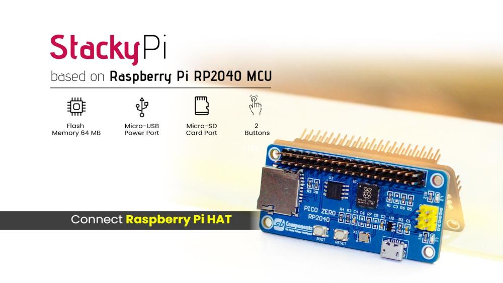
-
Couple of months ago, I bought a "Raspberry Pi Pico" to get some hands-on experience of it and to create some amazing projects using it. But since then, it has just been sitting on my desk, collecting dust. Today after a very long wait, I finally have decided to create a short video tutorial to show you guys how to get started with the Raspberry Pi Pico. Topics Covered In this tutorial, I am going to discuss: 1. What is a Raspberry Pi Pico? 2. The technical specifications of the board 3. How to program Pico using C/C++ and MicroPython a. Programming Raspberry Pi Pico using "Arduino IDE" i. Preparing the Arduino IDE ii. Loading the Blink Example iii. Demo b. Programming Raspberry Pi Pico using "Tonny Python IDE" i. Installing MicroPython on Pico ii. Installing Tonny Python IDE iii. Loading the Blink Example iv. Demo 4. Difference between Raspberry Pi Pico and Arduino 5. Advantages and Disadvantages of this board What is Raspberry Pi Pico? Raspberry Pi Pico is a low-cost microcontroller. It can be used to control other electronic modules and sensors same as any other microcontroller. Pico is not a Linux single board computer, rather it is a microcontroller like Arduino. Since, its a microcontroller it doesn't come with all the overheads that a computer brings and hence consumes much less current. actually it is more like Arduino than Raspberry Pi. Pico is not a rival of Raspberry Pi Zero, it actually can work in conjunction with the regular Pi's. Pico is breadboard friendly and has 40 GPIO pins operating at 3.3v (20 on each side). It has a Dual-Core ARM Cortex M0+ processor. Pico's brain - the RP2040 microcontroller chip is designed by Raspberry Pi in United Kingdom. It can be powered either via the micro USB port, or via the VSYS GPIO pin by providing voltage between the range of 1.8V to 5.5V. Technical Specifications of Pico Raspberry Pi Pico is absolutely different from all other Raspberry Pi models. Pico is one of the first microcontrollers to use the RP2040 "Pi Silicon" processor. It is a custom "System on Chip" (SoC) developed by the Raspberry Pi team in UK which features a dual core Arm Cortex M0+ processor running at 133 MHz, 264KB of SRAM and 2MB of flash memory for storing files on it. Specifications: - Microcontroller: RP2040 designed by Raspberry Pi in the UK - Processor: Dual-Core Arm Cortex-M0+ processor, flexible clock running up to 133 MHz - Input power: 1.8 - 5.5 V DC - Operating temperature: -20°C to +85°C - Dimensions: 51.0 x 21.0 mm - Onboard Sensors: Temperature Sensor - Memory: 264KB of on-chip internal SRAM and can support up to 16MB of off-chip Flash 2MB on-board QSPI Flash (Adafruit's Feather RP2040, features 16MB of storage) - GPIO: It has 40 GPIO through-hole pins also with edge castellation - 26 × multi-function 3.3V GPIO pins, which includes 3 analogue inputs (The Analog inputs is something other Raspberry Pi's lack. They use variable voltages to connect to devices like a potentiometers, joystick or a LDR) - 2 × SPI, 2 × I2C, 2 × UART, 3 × 12-bit ADC, 16 × controllable PWM channels - 8 × Programmable I/O (PIO) state machines for custom peripheral support that can offload many kinds of timing-critical processes from the CPU - Other Features: - 1 × Contains 1 × USB 1.1 controller and PHY, with host and device support - Accurate clock and timer on-chip - Low-Power sleep and dormant modes - Accelerated integer and floating-point libraries on-chip - Works with Windows, Mac, Linux machines and Raspberry Pi Computers - Provides drag-and-drop programming using mass storage over USB The one biggest disadvantage of the Raspberry Pi Pico is that there is no WiFi or Bluetooth on it. ESP32 and ESP8266 which you can buy for similar price comes with WiFi and Bluetooth (ESP32). Surely we can add wireless connectivity via external components, however that would require a little bit more knowledge and experience to get it working. Since Pico is not a computer, we need to write our codes on a different machine using an external application and then "flash" the code onto the microcontroller over USB. Pinout Diagram: Here is the top view of the pinouts on the Raspberry Pi Pico. The pin-labels are on the bottom side of the board. How to program Pico using C/C++ and MicroPython Pi Foundation officially supports MicroPython and C/C++, however high-level programming language like CircuitPython (A fork of MicroPython created by Adafruit), and Drag and Drop Python Editor like Pico Piper which adds further enhancements and can be used to program the Pico boards. Programming Raspberry Pi Pico using Arduino IDE Python and C/C++ are both great for programming Picos. However, being able to program a Pico just like an Arduino would help us to integrate the Pico into the Arduino ecosystem. One of the best reasons to do this is because of the availability of libraries to integration of modules, sensors, and other complex stuff without having to write the entire code from scratch. i. Preparing the Arduino IDE To start, let go to Tools > Boards > Boards Manager and search for "Pico", select "Arduino Mbed OS RP2040 Boards" and hit the install button. Connect the micro USB cable to the Pico and then press and hold the "BOOTSEL" button before plugging the USB cable into the computer. Release BOOTSEL once the drive RPI-RP2 appears on your computer. Now, go to Tools > Port and you will now be able to see the number of the COM Port. ii. Loading the Blink Example Go to Files > Examples > Basics > Blink and click on Upload, this will load the code to the Pico board. iii. Demo After the IDE finished uploading the code, you will see the Pico's onboard LED blinking. You can now use your Pico like an Arduino and program it using the Arduino IDE. Programming Raspberry Pi Pico using Tonny Python IDE You can program your Pico using MicroPython by connecting it to a computer via USB and then dragging and dropping files to it. i. Installing MicroPython on Pico Installation of MicroPython on Pico requires a "UF2" file to be copied onto it. A UF2 file is a "binary data file" which contains a program that can be transferred from a PC to a microcontroller, such as an Arduino or Pico circuit board. To load MicroPython on Pico: 1. Download "MicroPython UF2 file" from the link provided in the description below. 2. Connect the micro USB cable to the Pico and then press and hold the "BOOTSEL" button before plugging the USB cable into the computer. Release BOOTSEL once the drive RPI-RP2 appears on your computer. 3. Drag and drop the UF2 file onto the RPI-RP2 volume. 4. Your Pico will reboot. That's it, you are now running MicroPython on your Pico. ii. Installing Tonny Python IDE To write code and save files to Pico we are going to use the "Thonny Python IDE". Thonny comes with built-in Python 3.7, so just one simple installer is what you need to learn programming. To get started: 1. Download and install "Thonny" free from the Thonny website for your version of OS. The website's link is in the description below. Note: If you are running "Raspberry Pi OS" then Thonny is already installed on it, but may need to update it to the latest version sudo apt update && sudo apt upgrade -y 2. Connect the Raspberry Pi Pico to your computer. Then, in Thonny go to Tools > Options and click on the "Interpreter" tab. From the interpreter dropdown list select "MicroPython (Raspberry Pi Pico)". The port dropdown menu can be left to "automatically detect the Pico". Click "OK" to close. 3. A Python Shell called "REPL" (Read, Eval, Print, Loop) will popup to show that the Pico is connected and working. iii. Loading the Blink Example 1. Click in the main editor pane of Thonny and enter the following code to toggle the onboard LED. from machine import Pin, Timer led = Pin(25, Pin.OUT) timer = Timer() def blink(timer): led.toggle() timer.init(freq=2.5, mode=Timer.PERIODIC, callback=blink) 2. Click the "Run" button to execute the code. 3. Thonny will ask whether you want to save the file on "This computer" or the "MicroPython device". Choose "MicroPython device". Enter "blink.py" as the file name. Make sure you enter ".py" as the file extension so that Thonny recognizes it as a Python file. iv. Demo You should now see the onboard LED switching between on and off until you click the Stop button. Difference between Raspberry Pi Pico and Arduino * Before Raspberry Pi Pico, Raspberry Pi has always been know for their single board computers. However, in 2021 Raspberry Pi Foundation stepped a few steps forward and launched the Raspberry Pi Pico giving a head-to-head challenge to Arduino and all other board based microcontrollers. * Arduino was first introduced in 2005 and since then Millions of Arduino Units have been sold in the market. Compared to that, the response Pico received after its initial launch in 2021 is absolutely mind-blowing. * Both units are made for automating applications that don’t involve human intervention. * Pico can be used alone or in combination with Arduino for Automation and AI purposes. * Both modules are different in terms of power consumption, value, functionality, and price. * Pico boards come unsoldered however Arduino comes pre-soldered or unsoldered. * Pico module supports MicroPython and C/C++, while Arduino codes are written in C/C++ using Arduino.IDE. So which one to go for… Pico or Arduino? Advantages and Disadvantages Now lets have a look at the Pros and Cons of this microcontroller board. Advantages: * Raspberry Pi Pico is cheap, very small, and easy to use microcontroller * Pico is a dual core device coupled to a high-performance bus matrix, which means its both cores can give you the full performance concurrently * Pico consumes very low power * Pico is a breadboard friendly * Pico can be programmed using C/C++ and MicroPython * Pico can be programmed using Arduino IDE * Pico has 26 × multi-function 3.3V GPIO pins (23 Digital + 3 Analogue) * Pico comes with 8 x Programmable IO (PIO) and 2 x Analog Inputs * Pico boots quickly and doesn’t require a safe shutdown Disadvantages: * Pico completely lacks WiFi and Bluetooth without any add-ons * It lacks the GPIO markings on the top side of the board * The board comes unsoldered so you will have to solder the header pins or surface mount it to use it in your project * GPIO pins are 3.3V, which could be seen as a disadvantage, however devises designed for 5V can still be used with 3V via a voltage divider or a logic level converter. * Pico still uses micro-USB port. While many other microcontrollers have moved to USB-C, Pico is still coming with the micro-USB port If you have a Windows, Apple, Linux or even a Raspberry Pi, then you are already well in your way to program the small, cute, and gorgeous Raspberry Pi Pico in your next project. I bet, there must be a lot of project ideas going in your mind, so get your supplies and start coding. And, what are you waiting for??? Thanks Thanks again for checking my post. I hope it helps you. If you want to support me subscribe to my YouTube Channel: https://www.youtube.com/user/tarantula3 Blog Posts: https://diyfactory007.blogspot.com/2022/01/getting-started-with-raspberry-pi-pico.html Video: https://youtu.be/vO_2XWJDF70 Other Resources: RP2040 Datasheet : https://datasheets.raspberrypi.com/rp2040/rp2040-datasheet.pdf Hardware design with RP2040 : https://datasheets.raspberrypi.com/rp2040/hardware-design-with-rp2040.pdf Raspberry Pi Pico Datasheet : https://datasheets.raspberrypi.com/pico/pico-datasheet.pdf Getting started with Raspberry Pi Pico : https://datasheets.raspberrypi.com/pico/getting-started-with-pico.pdf MicroPython UF2 : https://micropython.org/download/rp2-pico/rp2-pico-latest.uf2 Thonny website : https://thonny.org/ Piper Make: https://make.playpiper.com/ CircuitPython 7.1.0: https://circuitpython.org/board/raspberry_pi_pico/ Support My Work: BTC: 1M1PdxVxSTPLoMK91XnvEPksVuAa4J4dDp LTC: MQFkVkWimYngMwp5SMuSbMP4ADStjysstm DOGE: DDe7Fws24zf7acZevoT8uERnmisiHwR5st ETH: 0x939aa4e13ecb4b46663c8017986abc0d204cde60 BAT: 0x939aa4e13ecb4b46663c8017986abc0d204cde60 LBC: bZ8ANEJFsd2MNFfpoxBhtFNPboh7PmD7M2 Thanks, ca again in my next tutorial.
-
AI Smart agriculture control Device Abstract: Agriculture is the broadest economic sector and plays an important role in the overall economic development of a nation. Technological advancements in the arena of agriculture will ascertain to increase the competence of certain farming activities. Smart Farming is a farming management concept using modern technology to increase the quantity and quality of agricultural products. Farmers in the 21st century have access to LoRa, soil scanning, data management, and Internet of Things technologies, web. Our device focuses on the measurement of physical parameters such as soil moisture content, nutrient content, automatic irrigation, pH of the soil and automatic sent notification phone application that plays a vital role in farming activities. Keyword: Agricultural innovation, IoT, LoRa, Power Management, ARM, Data Management Introduction: Smart farming based on IoT technologies will enable growers and farmers to reduce waste and enhance productivity ranging from the quantity of fertilizer utilized to the number of journeys the farm vehicles have made. In IoT-based smart farming, a system is built for monitoring the crop field with the help of sensors (light, humidity, temperature, soil moisture, etc.) and automating the irrigation system. The farmers can monitor the field conditions from anywhere using smart app. IoT-based smart farming device is highly efficient when compared with the conventional approach. The applications of IoT-based smart farming not only target conventional, large farming operations, but could also be new levers to uplift other growing or common trends in agricultural like organic farming, family farming (complex or small spaces, particular cattle and/or cultures, preservation of particular or high quality varieties etc.), and enhance highly transparent farming. Now, let’s discuss the major applications of IoT-based smart farming device that are revolutionizing agriculture. Hardware: Soil Sensor: The Soil Moisture Sensor uses capacitance to measure the water content of soil (by measuring the dielectric permittivity of the soil, which is a function of the water content). Simply insert this rugged sensor into the soil to be tested, and the volumetric water content of the soil is reported in percent. Temperature sensor (DHT 11): Measure the Temperature and humidity Photoresistor (LDR): Check day or night position LoRa ARM development board : This is a low power single board computer inbuild Wi-Fi, LoRa connectivity also has Digital and analog pins. Smart Agriculture Device Features: 1.This device no need external power (inbuild 5-volt Power bank & solar cell), 2. real-time Soil Moisture sensor measure the soil and sent data to the Server, 3.Temperature, photoresistor measure the weather condition. 4. Both way communication (device can send notification & received command from web or app) 5. Dual control (Device ca run manual mode and automatic mode). 6. Dual communication (LoRa and wi-fi mode) System Hardware Implementation: First configure the FreeRTOS on EFB-REV1 board after successful configure of operating system we need configure GPIO library(J-Tag) to access the its GPIO. Install 5-volt solar cell and power bank for powerup the device 24x7. Soil Sensor connected to analog pin of A0, DTH11 connected to A3, Photoresistor connected to A6. Analog sensors measure data and sent via wireless media. EFB_REV1 development come with LoRa, Wi-fi also Bluetooth, for our project we used Wi-Fi and LoRa. For Wi- fi communication need a wifi receiver module which receive and sent sensor data to the cloud server. Another hand implemented the device for loRa communication (data send rang up to 5km), here we need a loRa receiver to receive and sent sensor data to the cloud server. Wi-Fi and LoRa connective protocol of our smart agriculture device uses depend on different location & situation. Firmware & Application software implementation: Application Software: Here we used cloud server to store the data, and help of Rest API sent the command to the device. Device firmware has two measure function (i) Manual mode: In manual mode device will work, user pre set value of the sensor in device using web or smart app. (ii) Automatic Mode: In automatic mode device sent the sensor value to cloud server and machine learning algorithm take decision according the data. Conclusion Thus, the IoT agricultural applications are making it possible for ranchers and farmers to collect meaningful data. Large landowners and small farmers must understand the potential of IoT market for agriculture by installing smart technologies to increase competitiveness and sustainability in their productions. With the population growing rapidly, the demand can be successfully met if the ranchers, as well as small farmers, implement agricultural IoT solutions in a prosperous manner.
-
My personal user-case on how to make Skype work great on Raspbian. For me, this result seems a bit faster and more stable video streaming and less overall lagging. Learn from my Skype on Raspberry Pi article. P.S. This guide is likely to be applicable to other ARM devices.
-
There are a lot of ways to use the Raspberry Pi (and other ARM-based) mini computer boards. I've wondered if it's possible to make up something like a music controller hub center with Spotify. So, read my experiment about running Spotify on RPi
-
To emulate any type of software on any ARM development boards like Raspberry Pi a Virtualbox software is usually used. Learn the Virtualbox alternative for RPI (or any other ARM) with greater performance.
-
Another and less complicated way to enjoy Plex on your Raspberry Pi (or any other ARM Device)
-
 Hello Everyone,We are pleased to announce the launch of our online store - Mynics.All of you are requested to check the website and do give us your valuable feedback.You can do the following at Mynics.in- Shop for electronics and robotics- Blogs- Forums- Projects and VideosWe are soon rolling out some great competitions and offers, do follow us to stay updatedhttps://www.facebook.com/mynics.in/http://stalkture.com/p/mynicsinsta/4934651665/https://plus.google.com/104613178419222567531Time to show your creativity and leave the rest to Mynics.Cheers,Team Mynics.
 -
It's great when you've got your own cloud storage server. OwnCloud is the one, that can help. Especially, if set up on an ARM-device (like Raspberry Pi) it is also savvy and simple. Learn my experience how I have succeeded to install OwnCloud on Raspberry Pi (if you like it and have some other ARM device, go ahead and try this tutorial. Post the results to this topic)
-
There are two emulators: ExaGear Desktop and QEMU. So, I've decided to carry out a fair survey and compare the performance of these two. Without the bias, here are the results in QEMU vs ExaGear performance comparison article ----------------------------- P.S. To make sure, carry out your own experiment and post the results to this topic. What if you will get the different output?
-
Communication is great when it's easy and free. Here is the way to setup the popular messenger Telegram on Raspberry Pi
-
Free open-source and cross-platform alternative to Microsoft .NET Framework is Mono and it also can be ported to Raspberry Pi. Read more: Mono on Raspberry Pi
-
What if Windows can be started on ARM devices? Do you really need to reach your goals? The answers are in the article: Windows 7 on Raspberry Pi
-
Another way of playing great PC games on Raspberry Pi. Simply turn your device into a fast Raspberry Pi gaming emulator
-
Here is a good way to setup VPN using Raspberry Pi device.
-
TeamViewer, VNC or SSH + X11 are the 3 ways to run a remote desktop on Raspberry Pi. Learn the details from my article and chose the best one for you.
-
Hi Guys, New to the forum so apologize if I'm posting it the wrong place I hope you find interesting my fully integrated RPi active speaker project, which I released as OSHW. Feel free to share in the site too if you think it's worth. Built, tested, works There was no such a product on the market when I was looking for, everybody routed the audio signal from the jack plug externally. My solution is compact. https://github.com/rfsparkling/RPi_Speaker Zoltan


