Problems with Logic: Smart people needed

Chirurgeon

Feb 9, 2012
2
Joined
Feb 9, 2012
Messages
2
:D Hello all :D

I am currently working on an A-level project for my coursework but I am having problems with the logic gate part of my circuit, my teacher suggested asking on an electronics forum. So I Signed up :)

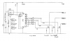
I am working on a traffic light controled junction, thus far I am using a 555 Astable (you gotta love these things) and a 4510b to produce a sequence. I then need to convert that sequence (using Logic gates) into colours; there are two traffic lights that I want to work in unison.

The sequence stages and the needed colours are as follows:
From left to right (Left being Q1 on the chip, to Q2, Q4 and finally Q8)
Code Colour 1 Colour 2
1000 / Green / Red
0100 / Green / Red
1100 / Green / Red
0010 / Green / Red
1010 / Amber / Red
0110 / Red / Red+Amber
1110 / Red / Green
0001 / Red / Green
1001 / Red / Amber
0000 / Red+Amber / Red


So my problem is getting the colours in this sequence, I am wondering how you would use logic gates to do this? Or even if there are other ways you would do it?
Many thanks
The Chirurgeon
 
Last edited:

Raven Luni

Oct 15, 2011
798
Joined
Oct 15, 2011
Messages
798
Greetings,

Interesting way of doing it. My first question would be do you have access to a wider range of components or are those the ones you have to work with?

I'm hesitant to say too much as the coursework is a test of your abilities afterall, but here are a few ideas for you:

- You have a number of reduntant counts. You only need 6. This makes using logic gates much simpler, and you just make the 6 (ie. the 7th count) reset the counter. In addition to controlling the outputs, the logic gates could also be used to pull up or ground different combinations of resistors and capacitors to change the timing of your 555 - so one count for each output state and each has its own timing :)

To get your head round that, a logic 0 can be considered a path to ground (this can also sometimes be undesirable so take care and use diodes where necessary)
 
Last edited:

(*steve*)

¡sǝpodᴉʇuɐ ǝɥʇ ɹɐǝɥd
Moderator
Jan 21, 2010
25,510
Joined
Jan 21, 2010
Messages
25,510
There's 10 separate states. I'd be looking at a 4017.

If I wanted to alter the timing for each step, I might use a diode and resistor from each 4017 output to inject more current into the 555's timing capacitor.
 

duke37

Jan 9, 2011
5,364
Joined
Jan 9, 2011
Messages
5,364
The 4017 Johnson counter is the way to go.
I constructed a sequencer to drive one light using the 4017. The different timing was achieved by using more than one output for each colour.
You may be interested in the circuit.
 

Attachments

  • Sequencer.png
    Sequencer.png
    16.4 KB · Views: 1,171

Chirurgeon

Feb 9, 2012
2
Joined
Feb 9, 2012
Messages
2
Thank you for all of your help with this, I really appreciate it :)

My first question would be do you have access to a wider range of components or are those the ones you have to work with?

I have access to a wide range of components, the department will even order things in if they don't have it.

Thank you for suggesting the 4017 as well, I am looking into that as we speak (I think I used it once before)
Also Thankyou for that circuit diagram, I think i see some bits I could use :D
 
Top