PCB not functioning

CocaCola

Apr 7, 2012
3,635
Joined
Apr 7, 2012
Messages
3,635

partyanimallighting

Oct 22, 2012
331
Joined
Oct 22, 2012
Messages
331
Hi CC, I checked the voltages on the second problematic pcb and here are the readings:
The voltages at the legs of VR1 are 12VDC and 21VDC and on VR2 it's 5VDC and 15VDC. I then checked the voltages from the tab of each one to Pin 28 on U3 and I got 5VDC on VR1 and 5VDC on VR2. I compared these readings with those of the relative datasheets and the voltages seem to be OK but remember, I'm a total novice at this and I could be wrong. So it seems to me that the LP2954IT on pcb #1 may be faulty but the two regulators on pcb #2 may be fine. What next?
 
Last edited:

CocaCola

Apr 7, 2012
3,635
Joined
Apr 7, 2012
Messages
3,635
I'm mostly out of diagnosing at this moment, I'll try to offer help when I can but I simply don't have the excess spare time right now to focus on this thread... If my time permits I will certainly interject when I can or when I spot something when I am looking the thread over...
 

QuantumCheese

Apr 27, 2012
74
Joined
Apr 27, 2012
Messages
74
Hi QC, first thing I did was check the voltages at the legs of VR1 and VR2 first and I got 12VDC and 15VDC on VR1 and -1.6VDC and 16VDC on VR2. I then checked the voltages from the tab of each one, VR1 and VR2, to Pin 28 on U3 and I got (-)0.5VDC on VR1 and (-)1,6VDC on VR2. I hope this is a start to a positive result.

The -ve voltages are not a good sign, i would be surprised if the 68hc705 has survived that. Edit: So don't swap it out with the other board or you might have two blown uProcs. Is this socketed? can it be removed?

I'm getting a little lots, can we talk about PCB (a) & (b) or something as i'm having difficulty knowing which set of symptoms with which board. ie is the dim led on the the board with the -ve voltage or the other one!

Maybe it's too early but i can't see a LP2954IT on the schematics?
 
Last edited:

partyanimallighting

Oct 22, 2012
331
Joined
Oct 22, 2012
Messages
331
The LP2954IT is VR2. When you have some time, we can try to sort out unit #2 first. VR1 (340T) and VR2 (LP2954) seem to be fine on this pcb so that's a start I suppose.
 

QuantumCheese

Apr 27, 2012
74
Joined
Apr 27, 2012
Messages
74
The LP2954IT is VR2. When you have some time, we can try to sort out unit #2 first. VR1 (340T) and VR2 (LP2954) seem to be fine on this pcb so that's a start I suppose.

Ah, coffee's kicking in in now.
Their marked on the PCB as 7812 & 7805. their equivalents, no problem,

Ok if we stick with this PCB then, which of the LED symptoms is it - status off or dim?
 

partyanimallighting

Oct 22, 2012
331
Joined
Oct 22, 2012
Messages
331
OK QC, wired up pcb #2 and I'm ready to go. Re-checked the voltages on VR1 and VR2 and the previous readings were correct. VR1 - 12VDC and 21VDC and on VR2 - 5VDC and 15VDC. VR1 and VR2 to U3 pin 28, 5VDC. So these regs seem fine. Or am I wrong?
 

QuantumCheese

Apr 27, 2012
74
Joined
Apr 27, 2012
Messages
74
OK QC, wired up pcb #2 and I'm ready to go. Re-checked the voltages on VR1 and VR2 and the previous readings were correct. VR1 - 12VDC and 21VDC and on VR2 - 5VDC and 15VDC. VR1 and VR2 to U3 pin 28, 5VDC. So these regs seem fine. Or am I wrong?

So long as the 5V and 12V are the outputs they would appear to be fine.
LED status?
 

partyanimallighting

Oct 22, 2012
331
Joined
Oct 22, 2012
Messages
331
According to the datasheet the outputs for these regs is pin 3 so they're fine. No LED though.
 
Last edited:

QuantumCheese

Apr 27, 2012
74
Joined
Apr 27, 2012
Messages
74
If the supply is OK, which it appears to be, I would concentrate on the LED itself for the moment as it's placed across the 5V rail.
one side is connected to vcc (+5v) and the other is connected to GND (or the tab of the regulator) via a resistor (330 ohm i think from memory). So with the power off i would measure the resistance between the led's legs and these two points, and also set your meter to diode test and measure the led itself - depending on the type of meter you have with the leads one way round it might light the led (if the led's OK)
 

partyanimallighting

Oct 22, 2012
331
Joined
Oct 22, 2012
Messages
331
Hi QC, here are the results:
R19 resistance - 326
R18 resistance - 326
Diode check LED 1 - 0.327
Diode check LED 2 - 1.6
R19 to LED resistance - 652
R18 to LED resistance - 715

The LED's did not light and the status of the LED's on this pcb is off.
 
Last edited:

partyanimallighting

Oct 22, 2012
331
Joined
Oct 22, 2012
Messages
331
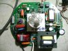
Hi Guys, if anybody's out there, I got unit # 2 repaired. Resistors R2 and R3 (22K/2W and24K/2W) were open and the pcb was a little scorched also. I replaced them, tested and the strobe works fine. There's 1 small problem. The green status LED does not function so I'll replace this first and, if the LED still doesn't work, I may need some help to sort it out. After this, on to unit # 1. To all concerned, I am very very careful when I'm testing this pcb. QC made the dangers of working on this type of pcb very clear to me and I am very careful, switching off and unplugging before I go anywhere near it. I basically treat it like an ex-wife. You don't really want to have anything to do with it, but you have to!! I'll post some pix next.
 

partyanimallighting

Oct 22, 2012
331
Joined
Oct 22, 2012
Messages
331
Me again. The LED was blown. Replaced it and the unit's fine. Someone please advise me as to the scorched parts on the pcb. I re-soldered everything back pretty good but please let me know if there's any cause for concern here.
 

Attachments

  • Diversitronics 004.jpg
    Diversitronics 004.jpg
    148.9 KB · Views: 180
  • Diversitronics 005.jpg
    Diversitronics 005.jpg
    58.1 KB · Views: 122

partyanimallighting

Oct 22, 2012
331
Joined
Oct 22, 2012
Messages
331
Hi guys, I'm testing pcb # 1 now. As I mentioned before, I'm getting 12VDC and 15VDC on VR1 and -1.6VDC and 15VDC on VR2. I'm getting (-)0.5VDC from VR1 to Pin 28 on U3 and (-)1.6VDC from VR2 to Pin 28 on U3 so I'm assuming VR2 is faulty or maybe some other device is blown and not allowing VR2 to get power. What the next step?
 

partyanimallighting

Oct 22, 2012
331
Joined
Oct 22, 2012
Messages
331
Update: I replaced LP2954 temporarily with LP7805 and replaced R2 (22K/2W)and R3 (24K/2W) and the green status LED lit but the lamp does not flash under control. I checked the lamp socket next and I'm getting 320VDC at the terminals. I then checked across SCR-22 and I'm getting 107VDC. When I short the pins on SCR-22 the lamp flashes. I then checked from the neutral line to Pin 5 on MOC8104 and I'm getting around 11VDC. When I short pins 4 and 5 on MOC8104 the lamp also flashes. At ground (0V) to the analog input pin 3 I'm getting 0VDC and from ground to the two 4005's I'm getting 5VDC before. From ground to the two 10K's I'm getting 0VDC. Any ideas?
 
Top