Effective Star Ground for Linear PSU

Proschuno11

Jan 3, 2026
6
Joined
Jan 3, 2026
Messages
6
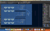
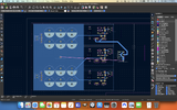
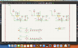
Greetings, I'm designing and building a Linear PSU that takes two AC inputs which it rectifies and filters them into a split supply consisting of LM317's and an LM337, each current boosted by a pass transistor. What I'm wanting to know is if the star grounding scheme I'm attempting would be sufficient; Blue colored, the entire rectangular plane surrounding the filter caps is all Ground, then each circuit surrounding the regulators is grounded on their own bus which then reaches the bit of ground plane nearest them. The 6 pin footprint to the most right will accept a cable with a molex connector which will provide the two positive voltages and the one negative voltage, along with ground, which will be a jumper running from this connection to another hole exactly between the caps as shown with the magenta . I'm planning on using this with Eurorack modular synthesizers, providing them with +12V, +5V, and -12V. I'm expecting to draw 3 amps from the +12V line, and about 1 amp each for the +5V and -12V lines.

I'm wanting to know
1. If this is even worth my time to use a star ground or if I should be using a ground plane
2. If so does what I have provided seem like an effective scheme?
 

Attachments

  • EurorackPSUGnd.png
    EurorackPSUGnd.png
    819.6 KB · Views: 10
  • Screenshot 2026-01-03 at 4.25.14 PM.png
    Screenshot 2026-01-03 at 4.25.14 PM.png
    541.1 KB · Views: 9
Last edited:

Delta Prime

Jul 29, 2020
2,988
Joined
Jul 29, 2020
Messages
2,988
I can’t see anything in your photo. It’s all fuzzy show a schematic of your design, please.
any other comment would be speculation at this point.
By the way, does this synthesizer come with garlic bread for all that spaghetti?
IMG_0782.jpeg
 

Proschuno11

Jan 3, 2026
6
Joined
Jan 3, 2026
Messages
6
I can’t see anything in your photo. It’s all fuzzy show a schematic of your design, please.
any other comment would be speculation at this point.
By the way, does this synthesizer come with garlic bread for all that spaghetti?
View attachment 69746
Sure does! Just be sure to use a spoon to twirl if you know how! I've uploaded a schematic and a better picture.
 

Delta Prime

Jul 29, 2020
2,988
Joined
Jul 29, 2020
Messages
2,988
Star ground are usually associated
With mixed signals, separating analog & digital grounds, creating defined loops for current flow.
Also…Star Grounds create high impedance ground,that are susceptible to differential mode noise, normally associated with RF (EMI) interference .
I would recommend a solid copper ground pour(Ground Plane); this would give you an low-impedance path at audio frequency whilst eliminating common mode interference (Noise)
That you will encounter with all that cabling (spaghetti).;)
 
Last edited:

Proschuno11

Jan 3, 2026
6
Joined
Jan 3, 2026
Messages
6
Do you think any of keep out area around the regulator circuitry would benefit me? Redirect all the noise generated from the modules towards the caps or am I overthinking this design?
 

Delta Prime

Jul 29, 2020
2,988
Joined
Jul 29, 2020
Messages
2,988
Do you think any of keep out area around the regulator circuitry would benefit me?
Marshall, your thoughts. Re-ask your question please.
I do not understand..
Redirect all the noise generated from the modules towards the caps or am I overthinking this design?
The LM317 does generate some noise itself I would never even consider it for high fidelity audio synthesizer power supplies But in your case you’re all right.
For large voltage differentials between input & output & high current draw 1 amp, the LM317 & its compliment the LM337 will dissipate significant power as heat, requiring a heat sink.
My before mentioned suggestion for your PCB design will minimize noise from the power supply & synthesizer itself.
I didn’t wanna critique your design, but since you asked; 6 filter caps all 4700uF are not needed. The datasheet for your adjustable positive & negative voltage Regulators give excellent examples. I would just be regurgitating that information. If you have trouble finding these datasheets let me know..
 
Last edited:

Proschuno11

Jan 3, 2026
6
Joined
Jan 3, 2026
Messages
6
I didn't mention that I purposely placed the regulators next to their pass transistors, with the intention that both will be attached to a heatsink. Thus when the transistor gets to about 150 'C, this should activate the regulators shutdown circuitry and cause it to naturally shutdown, preventing transistor failure.

I overdid the caps with the intention that I could use this board for more a bigger transformer (more current capability) than I am currently using it for, appropriately sizing the pass transistors to match. I wanted a design that I could use for several projects and what I just mentioned is a smaller one that I'd normally use this for.

As for explaining your first response I'm asking if making little miniature ground plans would be worth it, 'keep-out' areas meaning places where the ground plane doesn't exist. Notice in the attachment
 

Attachments

  • EurorackPSU Keepout.png
    EurorackPSU Keepout.png
    834.6 KB · Views: 1

Delta Prime

Jul 29, 2020
2,988
Joined
Jul 29, 2020
Messages
2,988
this should activate the regulators shutdown circuitry and cause it to naturally shutdown, preventing transistor failure.
It is not good engineering practice to rely on thermal shut down of your regulator for protecting your output power transistor, in the event of a short circuit, you’re transistor will experience max smoke.
 

Proschuno11

Jan 3, 2026
6
Joined
Jan 3, 2026
Messages
6
It is not good engineering practice to rely on thermal shut down of your regulator for protecting your output power transistor, in the event of a short circuit, you’re transistor will experience max smoke.
What should I do then for overcurrent protection? I haven't found any info on this for current boosting the LM317/LM337 regulators.
 

Delta Prime

Jul 29, 2020
2,988
Joined
Jul 29, 2020
Messages
2,988
As it stands for your application you are using the(K.I.S.S) method, Keep It Simple Stupid. This is not a derogatory comment towards you.Not meant to be insulting. Is used in electronics industry when designing electronic circuits. it comes down to money &,time go with what you have you’ll be OK. There are always trade-offs in designing circuits. You build simple circuit upon simple circuit and it becomes a complex circuit.
There are others in this community that would be more than happy to help you out in your endeavors.
I got homework to do bye-bye.
 

Delta Prime

Jul 29, 2020
2,988
Joined
Jul 29, 2020
Messages
2,988
Greetings, I'm designing and building a Linear PSU that takes two AC inputs
Almost forgot; have you ever worked with AC your local power utilities Mains before? I ask for safety reasons… your schematic shows no step down power transformer,fuse, filters,or support circuitry before your full wave bridged rectifier
 
Last edited:

Proschuno11

Jan 3, 2026
6
Joined
Jan 3, 2026
Messages
6
Almost forgot; have you ever worked with AC your local power utilities Mains before? I ask for safety reasons… your schematic shows no step down power transformer,fuse, filters,or support circuitry before your full wave bridged rectifier
There will be a step-down transformer and related support circuitry supplying the board.
 
Last edited:

Delta Prime

Jul 29, 2020
2,988
Joined
Jul 29, 2020
Messages
2,988
What should I do then for overcurrent protection? I haven't found any info on this for current boosting the LM317/LM337 regulators
One very good simple option would be a classic crowbar circuit, stated before in a different thread by a well respected member of this community @danadak


Top