I saw this thing on ebay... Labeled as "Aviation Signal Tracer Vintage RF Gear" and with a description of "Have no info on this one other that it was purchased as a single item from a deceased estate from a relative of the deceased. They were keen for it to find purpose. I had intentions to test it and put it back into service but I’ve run out of time. Would be a great looking piece in a ham radio or electronics enthusiast’s lab/shed/shack! I believe it was hand crafted by the original owner."
How could I resist!
Here it is:

It is a strange mix of "looks like it's commercial" and "obviously bespoke". Was it something that got converted for a new use, or is it incredibly well hand crafted from scratch?
First thing is how it is powered:

Weird 5 pin plug. Looks a lot like some sort of valve pins. I've seen these in old equipment before. But what voltage(s)?
But let's take a closer look at the front panel:

This is clearly hand-crafted. Hand-written dial attached to a knob. The engraved and painted Mc/s certainly dates this device (or possibly just the knob). The carefully marked position for 455kHz on the IF range is worth noting. The fact that IF and RF are on separate ranges is interesting...

The meter also has handwritten numbering. I originally thought that the word VOLTS was printed and D.C. was added, but on closer inspection (with the closeup of the photo) it's clear that VOLTS is also hand written.

This made me chuckle. The marker against which you read the range value is inscribed on the meter. But the word RANGE on the panel is not hand-written. Was the meter added afterwards?

Some controls without knobs. A strange mix of "professional" and hand made labeling. The controls seem closer together than optimum, but given the labelling it seems unlikely that the control to the right was added. And that pot has a screwdriver adjustment. Hmmmm.....
Enough of the outside. What's inside?

The first peek, and it looks strangely under populated. There's a big gap on the right that might once have held a transformer? Maybe?

Taking a look underneath reveals a really interesting beast. Take a look at the resistors. Ignoring the higher powered ones, there are three types of resistor. It certainly does not look typical of a commercial manufacture. There's also different types of switches and valve bases.
A lot of this construction shows obvious efforts were made to reduce noise and also to make it look good.

This section, for example, where the wires have been carefully and deliberately bent to stay as close as possible to the chassis.

And these, which have been correctly fitted with the word "Australia" upside-down as is required in the southern hemisphere.

What do we have here? A pair of reasonably huge point contact diodes.

And hey, another different type of resistor. This time with hard marked values!
OK, let's look at the top again.

It looks a bit bare from here. Also, the chassis is in 2 parts, some holes have grommets, others don't. There's so many signs here that this is hand-built that I'm no longer considering it's a modified piece of commercial equipment.

And here's something I couldn't read.
CORNELL-DUBILIER ELECTRIC CORP
USA
REG UNDER US PATS
1,931,373-2,041,594-1,850,702
I was hoping it would tell me what it was!
anyway, for those interested:
* https://patents.google.com/patent/US1931373A/en
* https://patents.google.com/patent/US2041594A/en
* https://patents.google.com/patent/US2007792
I suspect, having read a bit of these patents, that this is a paper in oil capacitor. They talk about "halogenated diphenyl", and since polychlorinated biphenyls (PCB's) are examples of these, I think I want to stay away from the insides of this.
But back to the innards!

Here is the (probably) final tube. A VT-231. double triode audio tube. 6.3V 600mA heater, and probable max of 250V on the plate
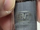
Going backwards (because that's what I do), the next tube is:

A 6BV7. A double diode pentode capable of 4W of output power. 6.3V 800mA heater. 180V (typ) 250V (max) plate voltage
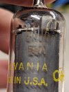
And then we get stuff in cans!

The first one is a 6AU6 that I had to get out of the socket to try to read. An RF Pentode (up to 50MHz with a 6.3V 300mA heater, and a 250V plate

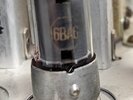
Looks like a 6BA6 to me. A variable mu RF pentode with 6.3V 300mA heater and 250V plate.
And finally (perhaps firstly)


Another 6BA6?
Well that's the tubes. I guess the HT is likely to be around 180V. Where does the heater current come from? They're all 6.3V, so maybe a 6.3V supply (I was wondering if they were in series - but that is very unlikely given the different heater currents. I need to trace out the power wiring.
Incidentally the power is 3 wires (red, green, and black). For a while I wondered whether the heater power was separate.

Did it come in through that jack? Well, no. It's pretty clear that the jack is connected to an output transformer.
But did you notice this?

This case MUST have been something in a former life.
Enough of the first looks. I'll need to trace some wiring next.
Oh, did you notice the background? For those who have been around long enough to have seen my earlier posts, this is a bit new.

Here's where I was working. It's the electronics lab at my local hackerspace.
How could I resist!
Here it is:
It is a strange mix of "looks like it's commercial" and "obviously bespoke". Was it something that got converted for a new use, or is it incredibly well hand crafted from scratch?
First thing is how it is powered:
Weird 5 pin plug. Looks a lot like some sort of valve pins. I've seen these in old equipment before. But what voltage(s)?
But let's take a closer look at the front panel:
This is clearly hand-crafted. Hand-written dial attached to a knob. The engraved and painted Mc/s certainly dates this device (or possibly just the knob). The carefully marked position for 455kHz on the IF range is worth noting. The fact that IF and RF are on separate ranges is interesting...
The meter also has handwritten numbering. I originally thought that the word VOLTS was printed and D.C. was added, but on closer inspection (with the closeup of the photo) it's clear that VOLTS is also hand written.
This made me chuckle. The marker against which you read the range value is inscribed on the meter. But the word RANGE on the panel is not hand-written. Was the meter added afterwards?
Some controls without knobs. A strange mix of "professional" and hand made labeling. The controls seem closer together than optimum, but given the labelling it seems unlikely that the control to the right was added. And that pot has a screwdriver adjustment. Hmmmm.....
Enough of the outside. What's inside?
The first peek, and it looks strangely under populated. There's a big gap on the right that might once have held a transformer? Maybe?
Taking a look underneath reveals a really interesting beast. Take a look at the resistors. Ignoring the higher powered ones, there are three types of resistor. It certainly does not look typical of a commercial manufacture. There's also different types of switches and valve bases.
A lot of this construction shows obvious efforts were made to reduce noise and also to make it look good.
This section, for example, where the wires have been carefully and deliberately bent to stay as close as possible to the chassis.
And these, which have been correctly fitted with the word "Australia" upside-down as is required in the southern hemisphere.
What do we have here? A pair of reasonably huge point contact diodes.
And hey, another different type of resistor. This time with hard marked values!
OK, let's look at the top again.
It looks a bit bare from here. Also, the chassis is in 2 parts, some holes have grommets, others don't. There's so many signs here that this is hand-built that I'm no longer considering it's a modified piece of commercial equipment.
And here's something I couldn't read.
CORNELL-DUBILIER ELECTRIC CORP
USA
REG UNDER US PATS
1,931,373-2,041,594-1,850,702
I was hoping it would tell me what it was!
anyway, for those interested:
* https://patents.google.com/patent/US1931373A/en
* https://patents.google.com/patent/US2041594A/en
* https://patents.google.com/patent/US2007792
I suspect, having read a bit of these patents, that this is a paper in oil capacitor. They talk about "halogenated diphenyl", and since polychlorinated biphenyls (PCB's) are examples of these, I think I want to stay away from the insides of this.
But back to the innards!
Here is the (probably) final tube. A VT-231. double triode audio tube. 6.3V 600mA heater, and probable max of 250V on the plate
Going backwards (because that's what I do), the next tube is:
A 6BV7. A double diode pentode capable of 4W of output power. 6.3V 800mA heater. 180V (typ) 250V (max) plate voltage
And then we get stuff in cans!
The first one is a 6AU6 that I had to get out of the socket to try to read. An RF Pentode (up to 50MHz with a 6.3V 300mA heater, and a 250V plate
Looks like a 6BA6 to me. A variable mu RF pentode with 6.3V 300mA heater and 250V plate.
And finally (perhaps firstly)
Another 6BA6?
Well that's the tubes. I guess the HT is likely to be around 180V. Where does the heater current come from? They're all 6.3V, so maybe a 6.3V supply (I was wondering if they were in series - but that is very unlikely given the different heater currents. I need to trace out the power wiring.
Incidentally the power is 3 wires (red, green, and black). For a while I wondered whether the heater power was separate.
Did it come in through that jack? Well, no. It's pretty clear that the jack is connected to an output transformer.
But did you notice this?
This case MUST have been something in a former life.
Enough of the first looks. I'll need to trace some wiring next.
Oh, did you notice the background? For those who have been around long enough to have seen my earlier posts, this is a bit new.
Here's where I was working. It's the electronics lab at my local hackerspace.