Sir KetchupSeed . . . . . . . . . . . . .(In actuality . . . . .' mater seed . . . . .since you can't grow "ketchups" and harvest their seeds. . . . . .
UNLESS you gazed upon the table top and done went and " seed " a bottle of ketchup . . . . . . a sittin' thar. )
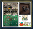
Here are my observations . . . . . you correct . . . . .or fill me in . . . if finer details from your photos, fails me..
I now
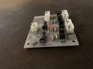
"read" the boards foils for you . . . . . follow me . . . .
PICTORIAL REFERENCING . . . . ALL marked up . . . . .
(Moved to VERY bottom )
THE SITUATION . . . . .
Look at the top left corners J4 connector . . .being non existent . . . but looking to the foil side, looking one pic down, it has a finer line foil joining its two lands into a constant ON position . . . we're thru with that factoid.
Back to the top pic to examine the J1 power connector . . . . . 2 pins used on it. Look down to the foil pic see my assignment of a BLACK diamond to the wall warts negative power supply in and an ORANGE diamond to its positive power supply input. The negative drops down that octapuss-ified-icated black line and travels
ALL OVER that board. . . . and I do mean ALL over it !
Now due to that "CLUX FLUTTER" , you will have to confirm for me if that ORANGE diamond and its power path down the RED line and has NO connection into that pad to its right that connects to a never/ now non existent battery back up at the VIOLET oval. I am expecting no connection.
NOW . . . lets track that power flow . . .after you first read the wall warts specs to see what the DC output of it is being and current capability and feed that info back to us . . .sort of expecting 9-12 VDC @ ? milliamperes.
If that IC is powered by +5 VDC expect the RED line power flow to pass down to the very bottom where that voltage level is supplied to the
YELLOW boxed driver transistors for one watch motor and the branch off of the same voltage for the other watches circuitry at the PINK supply lines path.
A logic HIGH from that IC1 , traveling down to either YELLOW triangles should have THAT watch running for that HIGH's duration in either a CW direction of the watches turntable , or a CCW direction . . . respective to the triangle that was selected..
Same is true of the other watch turntable, with it using the PINK colored mark ups.
Now is where I need your eyes and an ohmmeter set ito lowest ohms to confirm direct connections.
Confirm for me if the PINK branching path upwards , just below where I have the WHITE oval is correct.
I see 5 connections . . . .
1 . . .The top solder joint connection is a 3 direction ground plane connection
2 . . .Just below it is the Z marked connection that would feed 5 VDC into the IC if 5 VDC supply, if such voltage is used.
3 . . . Looks like that pad also ties into the Y-Z common junction foil but is its wire one of those leads of the round orange ceramic disc capacitor . . . .with that caps other lead going to the left sides ground plane ?
4 . . . . There seems to be an open spacing and then a solder pad with a wire lead enclosed and then a very short minor width foil trace that ties into a
5 . . . . Foil land that just appears to be an unpopulated solder blob.
BUT . . . . does that blob connect into that PINK supply line as is shown ?
And lastly, look at the BROWN O foil area, at its top right corner, it looks as if its sneaking a trace from its top right corner under the IC bottom.
Conform that, and then pass back what its bottom left corner ties into, in respect to those earlier reviewed 5 pads.
Looking at the bottom photos foils, looks like its populated in the D1 and 78L05 areas.
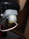
Looking at the top photo . . .who cannibalized those parts at YELLOW X's ??
EXPECTED MAIN POWER FLOW . . . .
If its Wall wart is connected and powered up, expect its full voltage to be present at the ORANGE diamond and pass down to the anode of the D1 (1N4007) diode ( RED flag area ) and goes into its anode and out its cathode (BLACK band on the left) and pass thru jumpered J4 and then down the RED power buss .
Now if you were to have just YELLOW mark up area of motor driver circuitry connected up to that watch turntables motor , have the wall wart plugged in and confirm its DC output at that RED buss , as is being referenced to the ground plane.
A test of that turntable could be made by using a 1K resistor with one lead extended with a wire to be able to stretch connections between the wire end at the RED power buss line and the other end of the resistor touched to either of the YELLOW triangle mark ups.
5V POWER SUPPLY . . . . . .
If that is the case, then the RED buss comes into the X input of the small TO-92 encased low power 5 V linear regulator I.C. as being a 78L05 as
ROBINS EGG BLUE . . . . MARK UP RECTANGLE.
There, that buss gets some additional filtering by the BLACK JEC axial E-capacitor . . . . tell us its voltage rating.
78L05 mid pin goes to the ground plane and the regulated 5VDC comes out the Y output to get some more filtering by the companion other JEC E-cap at Z connection . . .what is its voltage rating ?
The regulated 5 VDC supply then passes into the underneath area of the IC1 at the RED star. . . . . to go to its ? power pin
K1 and K2 . . . . . plugs
Are those connected into, as there two connections relate to modifying an input parameter to the IC1.
I.C.1 . . . . . . ? ? ?
If only that were a 16 pin unit . . . . . alas, its being only 14 . ., the use a MC4060 oscillator and its divider chain could be used to selectively tap off sub division outputs to get the ~ 800 rotations needed of the turntable throughout a 24 hr timing period of windee-windee..
Check out that chips top to see if it has had a flat black over coating to hide its markings try . . . .acetone . . . lacquer thinner . . .MEK . . . . Toluene . . .Xylene . . . . . methyl methacrylate . . . . . tiger piss ?
I can't see an indexing dot on top . . . . but think that I feebly see a small indexing gap at its left side. If that is true, its pins 2 and 3 would be the YELLOW turntables motor driver activation outputs . . . . the PINK turntables inputs foil paths.are hidden under the IC
COME YE FORTH . . . . . . . and talk towards me . . . .
Thaaaaaaaaaaaaaaaasssit . . . . .
73's de Edd . . . . .
A closed mouth gathers no feet.

 WhatsApp Image 2023-04-25 at 1.21.00 PM (1).jpeg176.5 KB · Views: 17
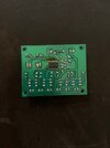 WhatsApp Image 2023-04-25 at 1.21.00 PM.jpeg231.1 KB · Views: 15
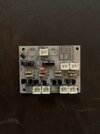 WhatsApp Image 2023-04-25 at 1.20.59 PM (1).jpeg214.2 KB · Views: 15
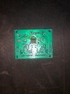 WhatsApp Image 2023-04-25 at 1.20.59 PM.jpeg369.7 KB · Views: 15
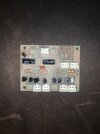 WhatsApp Image 2023-04-25 at 1.20.58 PM.jpeg447.2 KB · Views: 13