pearljammer
- Nov 5, 2009
- 2
- Joined
- Nov 5, 2009
- Messages
- 2
I saw this circuit on some electronics websit and built it for a project of mine.
Now my professor wants me to explain in detail how exactly it works...
All I know is that the basic principle of the circuit is that when SW1 is closed the circuit dissipates all the current in the 330K resisot.
When SW1 is open, the circuit supposedly begins to oscillate... but i have no idea which is the feedback path and which is the oscillator output...
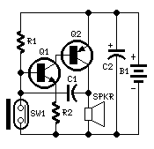
any help?
Parts:
R1____________330K 1/4W Resistor
R2____________100R 1/4W Resistor
C1_____________10nF 63V Polyester or Ceramic Capacitor
C2____________100µF 25V Electrolytic Capacitor
Q1____________BC547 45V 100mA NPN Transistor
Q2____________BC327 45V 800mA PNP Transistor
SW1____________Reed Switch and small magnet (See Notes)
SPKR___________8 Ohm Loudspeaker (See Notes)
B1_____________3V Battery (two A or AA cells wired in series etc.)
Now my professor wants me to explain in detail how exactly it works...
All I know is that the basic principle of the circuit is that when SW1 is closed the circuit dissipates all the current in the 330K resisot.
When SW1 is open, the circuit supposedly begins to oscillate... but i have no idea which is the feedback path and which is the oscillator output...
any help?
Parts:
R1____________330K 1/4W Resistor
R2____________100R 1/4W Resistor
C1_____________10nF 63V Polyester or Ceramic Capacitor
C2____________100µF 25V Electrolytic Capacitor
Q1____________BC547 45V 100mA NPN Transistor
Q2____________BC327 45V 800mA PNP Transistor
SW1____________Reed Switch and small magnet (See Notes)
SPKR___________8 Ohm Loudspeaker (See Notes)
B1_____________3V Battery (two A or AA cells wired in series etc.)



