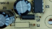
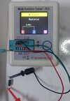
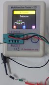
L2 on a PCB silk screened and written on schematic's refers to a component that has inductance, whose value would be in Henry's. That's the fancy way to describe a coil . By the way you see L1 there's nothing there no coil no inductor. For DC inductors will show up as a short circuit this is normal there is a DC resistance to the coil but as you discovered the resistance is so small your meter thinks it's a short circuit. What you must do is get a LCR meter and measure it's inductance.
So unfortunately this component
Would check okay to me if I was troubleshooting and I would move on something else is wrong.
I misspoke un-solder one lead of L1 that inductor and check again
Hi Delta Prime,
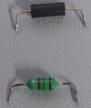
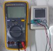
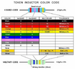
Thank you for your reply, I checked L2 with my meter and it comes up as a resistor with 0.04 ohm, also There was a inductor with 1.53mH in L1 which looks like a resistor!
Well put them back! Just kidding what seems to be the problem you are having is it visually L2 looks like a diode and L1 looks like a resistor photos please
Stay with me... concentrate... pay attention... we can find out right now inductors add when put or connected in series
Just like resistors they add as well when put in series. Therefore we already know the inductance of L1 add L2 in series with L1 measure the total inductance.
It's not really an inductor - it's a ferrite suppressor, just a piece of wire passing through the core of a piece of ferrite. OK, that's 'really' an inductor but the value will be smaaaaallllllll. Either way it reads short-circuit normally and your circuit will likely work even if you remove it and replace it with a short length of wire (but I wouldn't do that).
Very, very unlikely it's dud. What is the issue that made you suspect it in the first place?