Sallen Key Low Pass Filter, bandpass filter

Maglatron

Jul 12, 2023
2,025
Joined
Jul 12, 2023
Messages
2,025
so I'm going to be taking photos soon making progress still concentrating my full effort into this light board project should have the first column lit soon!
 

Maglatron

Jul 12, 2023
2,025
Joined
Jul 12, 2023
Messages
2,025
so now have started the lm3914 bar graph driver circuit one or two more sessions should see if it works!! thanks
 
Last edited:

Maglatron

Jul 12, 2023
2,025
Joined
Jul 12, 2023
Messages
2,025
UPDATE: few action shots and pictures still not finished the first column but only have to solder in the first LED bar graph column and the ribon cable is what I'm going to use to connect them! thanks, also not attached the mic yet and the wires that are loosely knotted are the power cables!
 

Attachments

  • DSCF0259.JPG
    DSCF0259.JPG
    310.7 KB · Views: 6
  • DSCF0271.JPG
    DSCF0271.JPG
    506.2 KB · Views: 6
  • DSCF0270.JPG
    DSCF0270.JPG
    516.5 KB · Views: 5
  • DSCF0269.JPG
    DSCF0269.JPG
    481.6 KB · Views: 5
  • DSCF0268.JPG
    DSCF0268.JPG
    724.1 KB · Views: 5
  • DSCF0267.JPG
    DSCF0267.JPG
    724.5 KB · Views: 5
  • DSCF0266.JPG
    DSCF0266.JPG
    556.7 KB · Views: 5
  • DSCF0265.JPG
    DSCF0265.JPG
    553.2 KB · Views: 5
  • DSCF0264.JPG
    DSCF0264.JPG
    634.1 KB · Views: 5
  • DSCF0263.JPG
    DSCF0263.JPG
    650.1 KB · Views: 5
  • DSCF0262.JPG
    DSCF0262.JPG
    389.8 KB · Views: 5
  • DSCF0261.JPG
    DSCF0261.JPG
    326.5 KB · Views: 5
  • DSCF0260.JPG
    DSCF0260.JPG
    288.4 KB · Views: 5
  • DSCF0258.JPG
    DSCF0258.JPG
    350.1 KB · Views: 6
Last edited:

Maglatron

Jul 12, 2023
2,025
Joined
Jul 12, 2023
Messages
2,025
I will be (hopefully) going on the project at twilight to solder in the LED's and the mic so we will soon see if it works, thanks! there are easier and cheaper ways of doing this spectrum analizer project but I wanted a certain look to the display (a kind of retro look)
Excellent, I’m looking forward to seeing it work.
I may have to make one myself:)
 

Maglatron

Jul 12, 2023
2,025
Joined
Jul 12, 2023
Messages
2,025
soldered half or the ribon to the bar graph LED's another 10 wires 20 joints and then the power lines too, hopefully get another chance to go on to the project tomorrow! thanks
 

Maglatron

Jul 12, 2023
2,025
Joined
Jul 12, 2023
Messages
2,025
so alor, I connected up the bar graph LED's and switched on the circuit all of the leds flash but then only the top 5 segments light and some are faint and some are solid so I think that I may have a problem with this part of the circuit, going to redo it next time any ideas why the top LED's light? thanks did not take photos and is it ok to use electrolytic caps, tell me your thoughts please! p.s none of the parts get hot or anything and might I add that for a split second all LED's light

Is it sound reasoning that the problem is with the LM3914 circuits because they drive the LED's? I think this part is bad going to rebuild at next possible time if I get the same result I will then proceed to thinking that the problem is from another part of the circuit!
 

Attachments

  • lifted refs.jpg
    lifted refs.jpg
    99 KB · Views: 2
Last edited:

Maglatron

Jul 12, 2023
2,025
Joined
Jul 12, 2023
Messages
2,025
So restarted the lm3914 bar graph LED driver circuits! just got to fit the 22k resistor and the LED's and join pin 9 of chip one to one of chip two and plug it in and see if it works out better this time will take pictures of results this time! thanks
 

Maglatron

Jul 12, 2023
2,025
Joined
Jul 12, 2023
Messages
2,025
So I believe that the circuit is rigged up properly now don't know if the mic polarity is correct this is the data sheet for the one that I have
the LED's are not responding to the low frequency and when I was packing away I realized that I forgot about the 22k resistor what would the reprecussions of not having this resistor be, thanks
 
Last edited:

Maglatron

Jul 12, 2023
2,025
Joined
Jul 12, 2023
Messages
2,025
from what I understand omnidirectional means it doesn't matter which way round I wire the mic
 

bertus

Moderator
Nov 8, 2019
3,836
Joined
Nov 8, 2019
Messages
3,836
hello,

term 1 is signal, where the resistor is connected
term 2 is ground

bertus
 

Maglatron

Jul 12, 2023
2,025
Joined
Jul 12, 2023
Messages
2,025
term 1 to the resistor of the pre-amp? where 12k and 10uF cap is connected

the 22k resistor I mentioned is the one in this picture over LED 11 of the lm3914 bar graph LED drivers
 

Attachments

  • preamp_comment.png
    preamp_comment.png
    186.5 KB · Views: 2
  • lifted refs.jpg
    lifted refs.jpg
    99 KB · Views: 2

bertus

Moderator
Nov 8, 2019
3,836
Joined
Nov 8, 2019
Messages
3,836
hello,

yes, term 1 goes to the connection point of the 12 k and 10 uf.

bertus
 

Maglatron

Jul 12, 2023
2,025
Joined
Jul 12, 2023
Messages
2,025
thanks and is it imperative to have the 22k resistor in the lm3914's circuit?
 

bertus

Moderator
Nov 8, 2019
3,836
Joined
Nov 8, 2019
Messages
3,836
hello,

the 22 k is given in the datasheet schematic.
it could be it is used for the two stage system.
check the comment in the datasheet.

bertus
 

Maglatron

Jul 12, 2023
2,025
Joined
Jul 12, 2023
Messages
2,025
hello,

the 22 k is given in the datasheet schematic.
it could be it is used for the two stage system.
check the comment in the datasheet.

bertus
I can't find the comment in the datasheet!
 

bertus

Moderator
Nov 8, 2019
3,836
Joined
Nov 8, 2019
Messages
3,836
Hello,

In the datasheet on page 7 the following is stated:
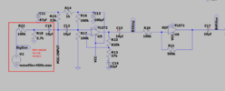
In order for the display to make sense when multiple
LM3914s are cascaded in dot mode, special circuitry has
been included to shut off LED No. 10 of the first device
when LED No. 1 of the second device comes on. The con-
nection for cascading in dot mode has already been de-
scribed and is depicted below.
As long as the input signal voltage is below the threshold of
the second LM3914, LED No. 11 is off. Pin 9 of LM3914
No. 1 thus sees effectively an open circuit so the chip is in
dot mode. As soon as the input voltage reaches the thresh-
old of LED No. 11, pin 9 of LM3914 No. 1 is pulled an LED
drop (1.5V or more) below VLED. This condition is sensed by
comparator C2, referenced 600 mV below VLED. This forces
the output of C2 low, which shuts off output transistor Q2,
extinguishing LED No. 10.
VLED is sensed via the 20k resistor connected to pin 11.
The very small current (less than 100 mA) that is diverted
from LED No. 9 does not noticeably affect its intensity.

It seems to be for dot mode.

I also found this page:

In the section cascading, the following is stated:
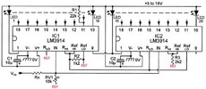
It is also important to remember the arrangement of the LEDs for cascading stages, as it's different to previous arrangements.
There is a 20kΩ resistor between supply and pin 11, in parallel with LED number 9 (pin 11), on all but the final stage.
In the final stage, pin 11 is connected directly to pin 9.
Pin 9 itself is connected to pin 1 of the next driver in parallel with LED number 1, as shown.

Bertus
 

Attachments

  • LM3914.pdf
    302.3 KB · Views: 1
Last edited:

Maglatron

Jul 12, 2023
2,025
Joined
Jul 12, 2023
Messages
2,025
okay I'm confused - surprise surprise, so I found this in the datasheet it says that pin 9 should be linked to positive for bar mode but on the schematic you provided a while back the pin 9 of the second chip is not connected at all and the pin 9 or the first chip is conecteed to the cathode of the LED 11 and pin 1 of the second chip, I want to have it set up in bar mode I appreciate that you have given me material to read and am reading it but I'm struggling can you post me a schematic of the working bar type circuit thats cascaded for 20 LED's please? thanks, maybe drawn in spice for me I can follow schematics for the practical building and soldering
1711103230418.png
 

Attachments

  • lifted refs.jpg
    lifted refs.jpg
    99 KB · Views: 0
Last edited:
Top