KostasGreco
- Jan 24, 2017
- 14
- Joined
- Jan 24, 2017
- Messages
- 14
Hi,
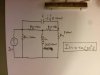
I need help with this problem. I am to solve it using either simple mesh method or junction method. Now my problem is that the impendance and reactance are given. BUT ! I know from theory that Xc and Xl can be calculated using the methods Xc=1/2πF and XL=2πfL only when current and voltage are in phase. In this case they are not. So do i have to make a phasor diagram first to calculate the real impedance and reactance or i am completly wrong?
I need help with this problem. I am to solve it using either simple mesh method or junction method. Now my problem is that the impendance and reactance are given. BUT ! I know from theory that Xc and Xl can be calculated using the methods Xc=1/2πF and XL=2πfL only when current and voltage are in phase. In this case they are not. So do i have to make a phasor diagram first to calculate the real impedance and reactance or i am completly wrong?
")