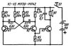
Simple multitester

caps

Jul 29, 2018
183
Joined
Jul 29, 2018
Messages
183
Simple multitester.
Quick check resistors, capacitors, diodes, transistors,open circuit.
Probes indicate the polarity of the diodes and transistors.
Check electrical installation and cable breaks.
Powerful beeper, simplicity, cost.
Indispensable for electrical work.
V1-V3-BC157,BC557,2N3905
 

Attachments

  • Multitester.jpg
    Multitester.jpg
    10.2 KB · Views: 10

Audioguru

Sep 24, 2016
3,656
Joined
Sep 24, 2016
Messages
3,656
Your very old circuit might not work when the silicon PNP transistors are damaged by avalanche breakdown of the reverse biased emitter-base junctions since the supply voltage of 9V is too high without having protection diodes.
The maximum allowed reverse emitter-base voltage is shown on the datasheets to be 5V. With a 9V supply the capacitors charge to about 8.1V then one transistor saturates causing the base of the second transistor to try to be +8.1V damaging the emitter-base junction a little each cycle. I have used a reverse-biased emitter-base junction as a 5V to 6.8V zener diode and with the collector junction added it makes a 5.7V to 7.5V Zener diode. Every transistor has a different breakdown voltage.

The circuit was probably designed to use old germanium transistors that have a much higher emitter-base breakdown voltage. This circuit using silicon transistors will be fine if the supply is reduced to less than 5.8V.
 

caps

Jul 29, 2018
183
Joined
Jul 29, 2018
Messages
183
This multitester has been working for me for 20 years already.
It is powered by a 9v battery. It is very economical, I rarely change the battery.
Multitester normally works with sufficient volume and at a battery voltage of 3V.
In my circuit I use 3 silicon transistors KT361.
 

Attachments

  • transistor-kt361.png
    transistor-kt361.png
    55.3 KB · Views: 6
Last edited:

Harald Kapp

Moderator
Moderator
Nov 17, 2011
14,271
Joined
Nov 17, 2011
Messages
14,271
This 'tester' needs some explanation:
- where do you attach probes?
- how do you use it?

The circuit per se is nothing but an astable multivibrator cum speaker.
 

duke37

Jan 9, 2011
5,364
Joined
Jan 9, 2011
Messages
5,364
You can use normal npn transistors if you put a diode (1N4148 etc) in series with each emitter.
I would have thought that R5 would be better in the emitter of V3 to control its current.
 

caps

Jul 29, 2018
183
Joined
Jul 29, 2018
Messages
183
- where do you attach probes?
- how do you use it?
Probes tester connect, breaking the power circuit.
About the rest wrote in the first message.
I used a beeper from an old phone.Its resistance is 22Ohm. Therefore, the sound is very powerful. You can check the electrical connections yourself at a certain distance.
You can use more miniature beepers with a resistance of 40 Ohms. The sound will be slightly weaker.
 
Last edited:

(*steve*)

¡sǝpodᴉʇuɐ ǝɥʇ ɹɐǝɥd
Moderator
Jan 21, 2010
25,510
Joined
Jan 21, 2010
Messages
25,510
The device is not running continuously, so the cumulative damage will probably be occurring slowly enough that the device will have a relatively long life.

However, I question it's use for testing base-emitter junctions of transistors. The fact that it's slowly killing itself is less if a problem than damaging a component under test.
 

caps

Jul 29, 2018
183
Joined
Jul 29, 2018
Messages
183
Before checking the semiconductor elements directly in the circuit, it is necessary to know their characteristics and application.
I have already said that the tester normally works when powered 3V. In addition, it has a small test current.
For all the time of using multi-tester, not a single semiconductor element has failed.
 

(*steve*)

¡sǝpodᴉʇuɐ ǝɥʇ ɹɐǝɥd
Moderator
Jan 21, 2010
25,510
Joined
Jan 21, 2010
Messages
25,510
I would recommend you read this thread.

It is clear that even the briefest breakdown of the EB junction, at even the lowest current causes damage to the junction. Whilst this may not cause failure, if a tester causes any damage, that's not a good thing.

Operated from 3V it would be much safer. However I would place the process so they just switch power to the oscillator. The relatively high current through the transducer, as well as any voltage spikes will be isolated from the device under test.

And I'd add diodes to protect the bases of the transistors because it's just simple, cheap, and safe.
 

caps

Jul 29, 2018
183
Joined
Jul 29, 2018
Messages
183
If they want to repeat this scheme, they can take into account your recommendations. Any changes that improve the work are always good.
I repeat, this is a simple tester, I mainly use it to check for breakage of various electrical circuits, contacts and fuses.
Unlike a multimeter, the test is convenient and fast. You can also add an LED.
For example, if you decide to check the light switch, then by hooking a tester to it, you can safely work in another room.
 
Last edited:

caps

Jul 29, 2018
183
Joined
Jul 29, 2018
Messages
183
- how do you use it?
By the tone of the sound of the beeper, you can approximately determine the resistance value in the tested electrical circuit.
By the duration of the decaying sound in the beeper, you can approximately estimate the presence of capacitance in the capacitor.
By the duration of a click in a beeper, one can estimate the presence or absence of capacitance in film capacitors.
This also applies to the breakdown or breakage of capacitors,zener diodes, transistors and other elements.
The tester is very effective when checking the integrity of printed conductors of different boards and short circuits between them.
Under the influence of the forum, I decided to upgrade my tester.
 

Attachments

  • Simple multitester.jpg
    Simple multitester.jpg
    33.5 KB · Views: 3
Last edited:
Top