

16-Bit I/O Expander with Serial Interface (SPI or I2C)
- Rajkumar Sharma
- 67 Views
- moderate
- Tested
- SKU: EL143464
- Quote Now
- 0 Likes

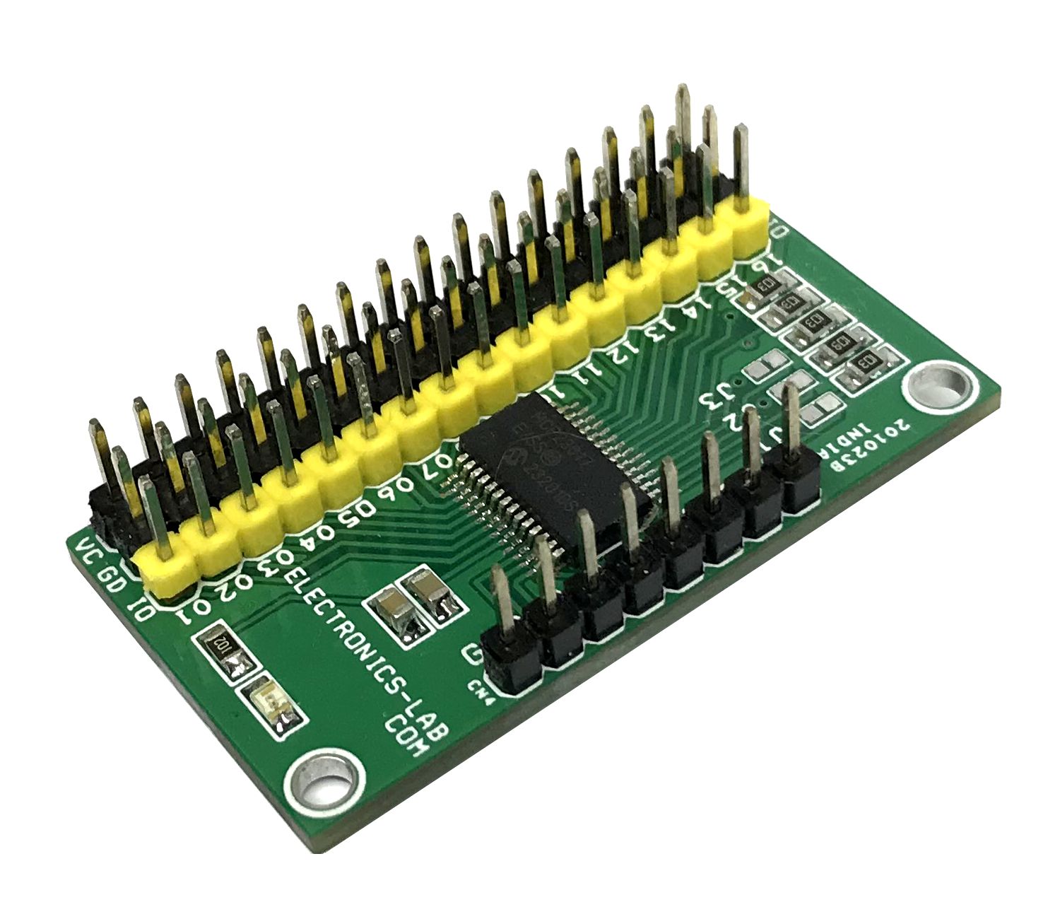
This project provides 16-bit, general-purpose parallel I/O expansion for I2C or SPI bus applications. The MCP23017 chip supports the I2C interface and the MCP23S17 chip is used for the SPI interface. The board can be populated with either SPI or I2C chip. Follow the connection diagrams for interface details.
Arduino Library for MCP23017 I2C Chip
- https://www.arduino.cc/reference/en/libraries/mcp23017-port-expander/
- https://github.com/ndomx/MCP23017-Arduino-Library
- https://learn.adafruit.com/adafruit-mcp23017-i2c-gpio-expander/arduino
- Arduino Library for MCP23S17 SPI Chip
Features
- Power Supply 1.8V to 5.5V DC
- 16-Bit Remote Bidirectional I/O Port (Pins GPA7, GPB7 are output only for MCP23017): – I/O pins default to input
- High-Speed I2C Interface (MCP23017):100Khz/400Khz/1.7Mhz
- High-Speed SPI Interface (MCP23S17): – 10 MHz (maximum)
- Three Hardware Address Pins to Allow Up to Eight Devices on the Bus
- Configurable Interrupt Output Pins: Configurable as active-high, active-low or open-drain
- INTA and INTB Can Be Configured to Operate Independently or Together
- Configurable Interrupt Source: Interrupt-on-change from configured register defaults or pin changes
- Header Connector for I2C/SPI Interface
- Header Connector provided for 16 I/0 Lines, VCC and GND for easy interface
- PCB Dimensions 43.97 x 24.29 mm
- 5mm Mounting Holes
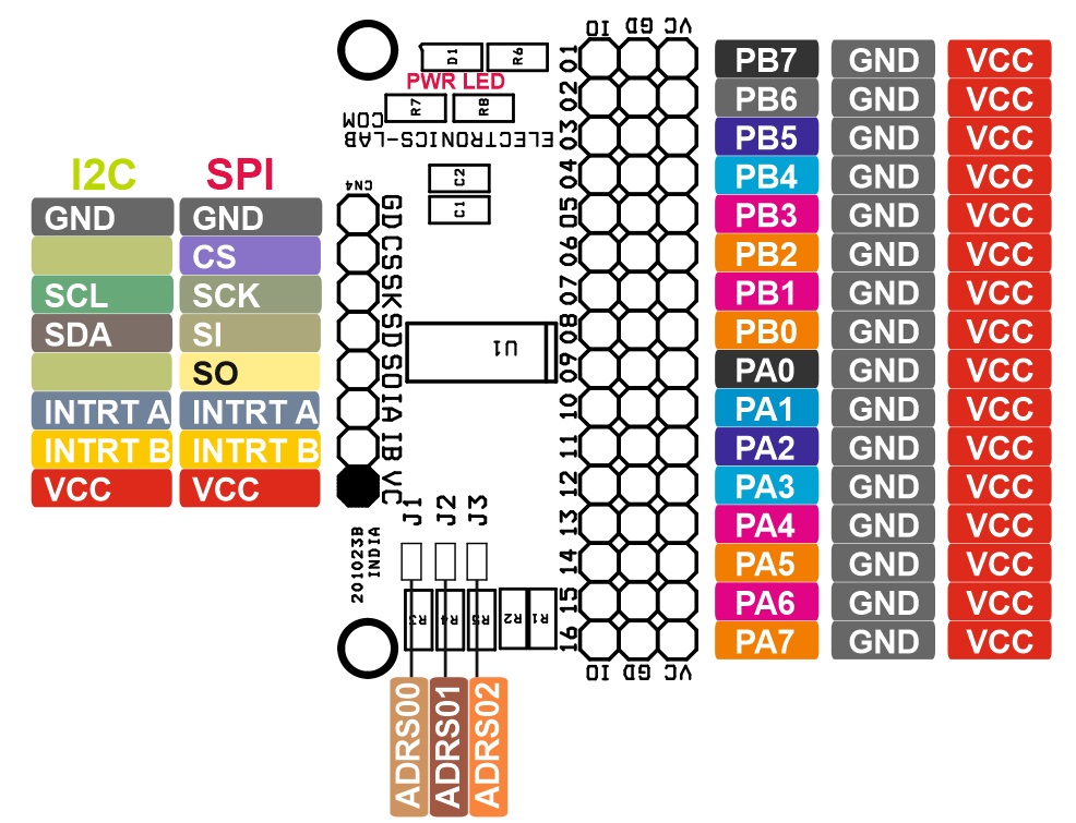
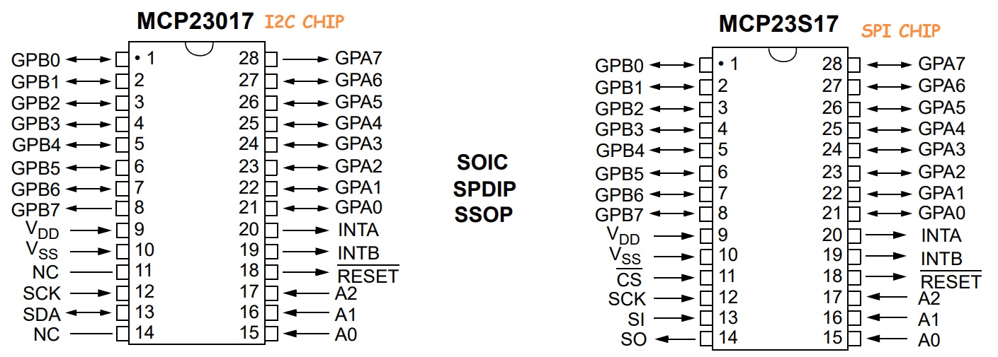
I2C VS SPI Pins
- NC/CS: Input NC (MCP23017)/Chip Select (MCP23S17)
- SCK: Input Serial clock input
- SDA/SI: Input/Output Serial data I/O (MCP23017)/Serial data input (MCP23S17)
- NC/SO Output: NC (MCP23017)/Serial data out (MCP23S17)
- INTB: Output Interrupt output for PORTB. Can be configured as active-high, active-low or open-drain.
- INTA: Output Interrupt output for PORTA. Can be configured as active-high, active-low or open-drain.
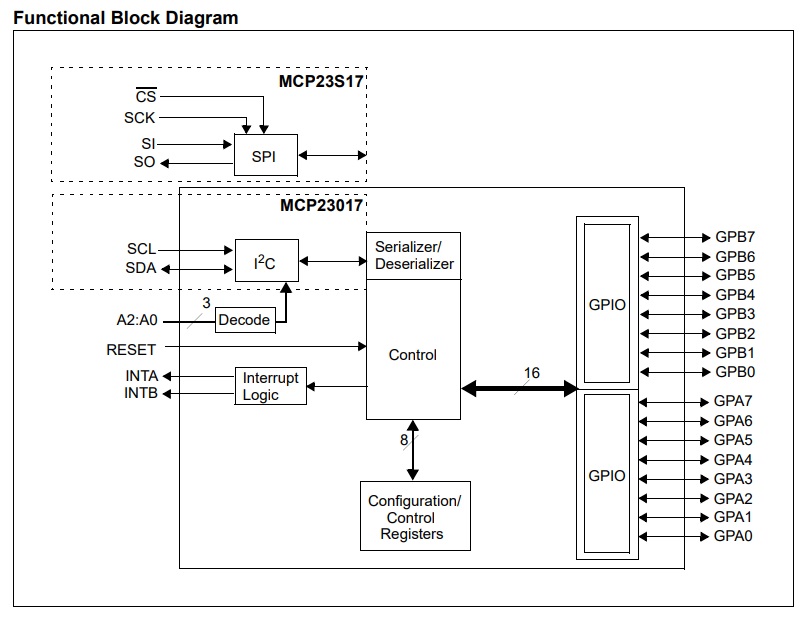
MCP23X17 consists of multiple 8-bit configuration registers for input, output and polarity selection. The system host can enable the I/Os as either inputs or outputs by writing the I/O configuration bits (IODIRA/B). The data for each input or output is kept in the corresponding input or output register. The polarity of the Input Port register can be inverted with the Polarity Inversion register. All registers can be read by the system host. The 16-bit I/O port functionally consists of two 8-bit ports (PORTA and PORTB). MCP23X17 can be configured to operate in the 8-bit or 16-bit modes via IOCON.BANK. There are two interrupt pins, INTA and INTB, that can be associated with their respective ports, or can be logically OR ’ed together so that both pins will activate if either port causes an interrupt. The interrupt output can be configured to activate under two conditions (mutually exclusive):
- When any input state differs from its corresponding Input Port register state. This is used to indicate to the system host that an input state has changed.
- When an input state differs from a preconfigured register value (DEFVAL register).
The Interrupt Capture register captures port values at the time of the interrupt, thereby saving the condition that caused the interrupt. The Power-on Reset (POR) sets the registers to their default values and initializes the device state machine. The hardware address pins are used to determine the device address.
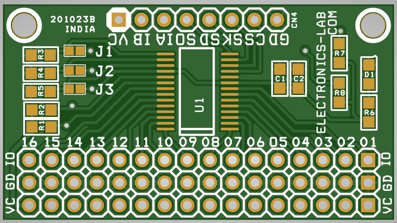
Connection
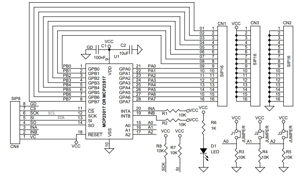
- CN1: Pin 1=01/PB7, Pin 2=02/PB6, Pin 3=03/PB5, Pin 4=04/PB4, Pin 5=05/PB3, Pin 6=06/PB2, Pin 7=07/PB1, Pin 8=08/PB0, Pin 9=09/PA0, Pin 10=10/PA1, Pin 11=11/PA2, Pin 12=12/PA3, Pin 13=13/PA4, Pin 14=14/PA5, Pin 15=15/PA6, Pin 16=16/PA7
- CN2: Pin 1 to 16 GND.
- CN3: Pin 1 to 16 VCC
- CN4: Pin 1 = VCC, Pin 2 =Interrupt B, Pin 3 = Interrupt A, Pin 4 = Serial Output, Pin 5= SI-SPI/SDA-I2C, Pin 6=SCK-SPI/SCL-I2C, Pin 7= CS-SPI, Pin 8 = GND
- D1: Power LED
- Jumper J1 = Address A0 (PCB Solder Jumper)
- Jumper J2 = Address A1 (PCB Solder Jumper)
- Jumper J3 = Address A2 (PCB Solder Jumper)
Schematic
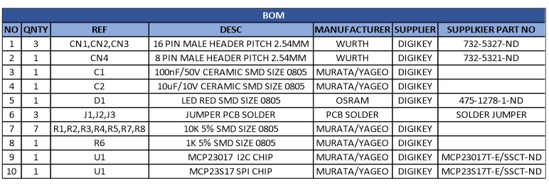
Parts List
| NO | QNTY | REF | DESC | MANUFACTURER | SUPPLIER | SUPPLKIER PART NO |
|---|---|---|---|---|---|---|
| 1 | 3 | CN1,CN2,CN3 | 16 PIN MALE HEADER PITCH 2.54MM | WURTH | DIGIKEY | 732-5327-ND |
| 2 | 1 | CN4 | 8 PIN MALE HEADER PITCH 2.54MM | WURTH | DIGIKEY | 732-5321-ND |
| 3 | 1 | C1 | 100nF/50V CERAMIC SMD SIZE 0805 | MURATA/YAGEO | DIGIKEY | |
| 4 | 1 | C2 | 10uF/10V CERAMIC SMD SIZE 0805 | MURATA/YAGEO | DIGIKEY | |
| 5 | 1 | D1 | LED RED SMD SIZE 0805 | OSRAM | DIGIKEY | 475-1278-1-ND |
| 6 | 3 | J1,J2,J3 | JUMPER PCB SOLDER | PCB SOLDER | SOLDER JUMPER | |
| 7 | 7 | R1,R2,R3,R4,R5,R7,R8 | 10K 5% SMD SIZE 0805 | MURATA/YAGEO | DIGIKEY | |
| 8 | 1 | R6 | 1K 5% SMD SIZE 0805 | MURATA/YAGEO | DIGIKEY | |
| 9 | 1 | U1 | MCP23017 I2C CHIP | MURATA/YAGEO | DIGIKEY | MCP23017T-E/SSCT-ND |
| 10 | 1 | U1 | MCP23S17 SPI CHIP | MURATA/YAGEO | DIGIKEY | MCP23S17T-E/SSCT-ND |
Connections
Function Diagram
SPI vs I2C Chip Pinout
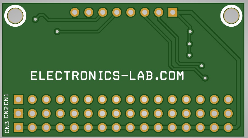
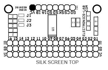
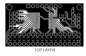
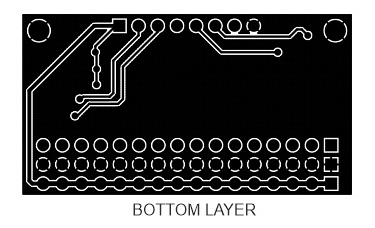
Gerber View
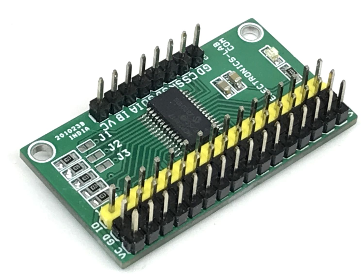
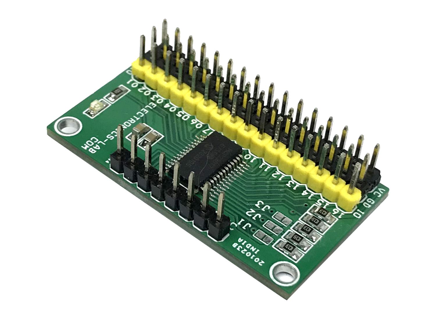
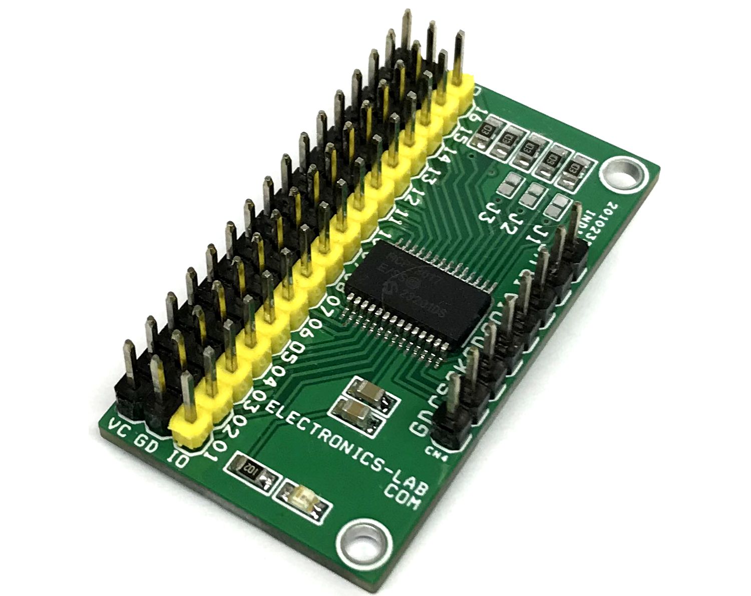
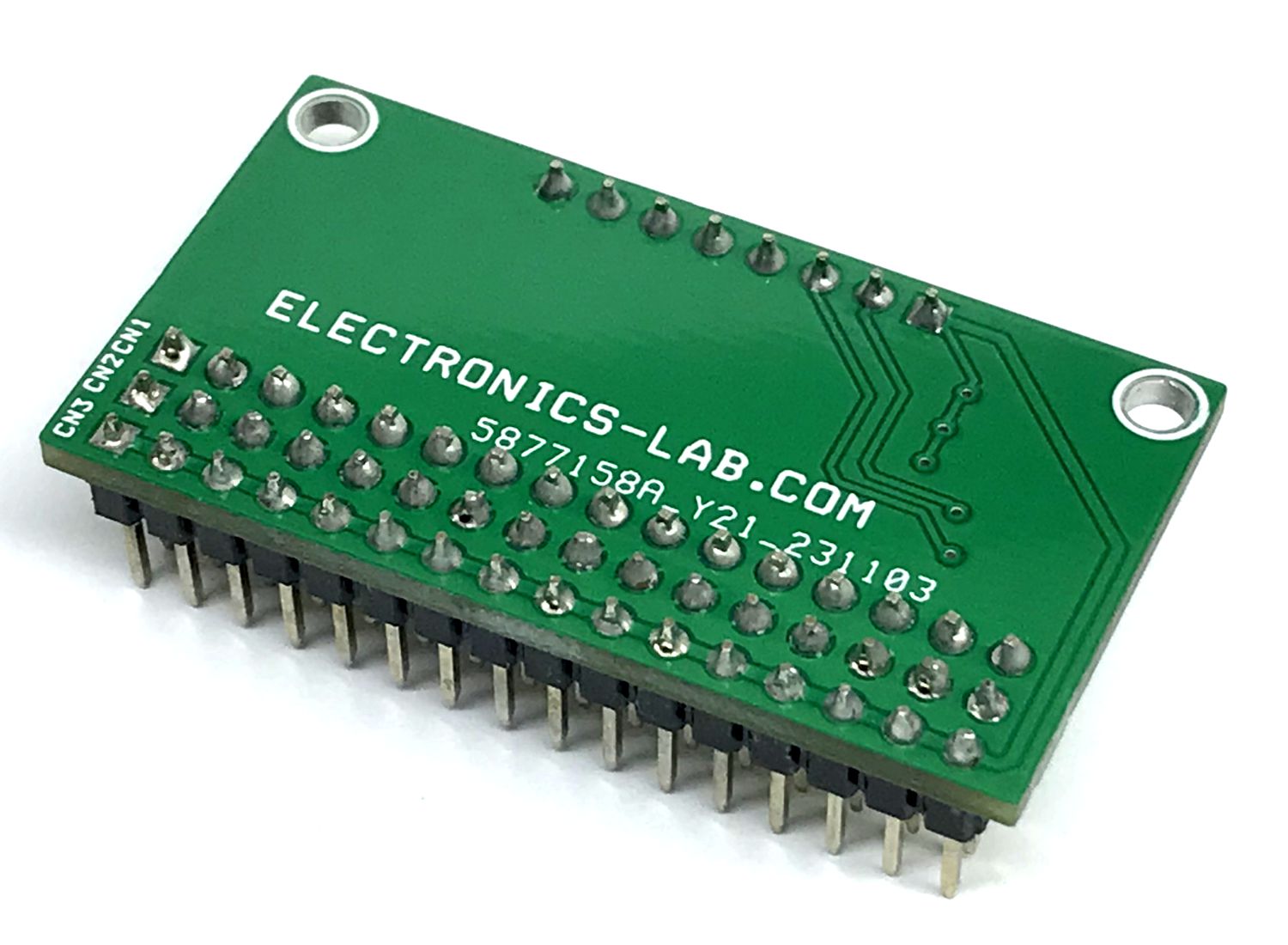
Photos
Video
MCP23017/MCP23S17 Datasheet
PCB


")

