2 Channel MOSFET Module
This is a low profile and small size two-channel MOSFET board that can drive loads up to 2 x 3A. The Power Supply is 5V to 14V DC.
This is a low profile and small size two-channel MOSFET board that can drive loads up to 2 x 3A. The Power Supply is 5V to 14V DC. Inputs and input Enable are TTL-level signals. The Output is by default enabled and an active high signal disables the output. Parallel Operation of Dual Outputs for Larger Driver Output Current is possible. The Circuit can drive a high-speed PWM signal as well as ON/OFF signal.
Features
- +5V to +14V Single Power-Supply Range
- Load up to 3A, each Channel
- IN-A, IN-B, ENB-A, ENB-B, TTL Level Inputs
- Dual Drivers with Enable Inputs
- Low 12ns Propagation Delay
- 6ns Typical Rise and 5ns Typical Fall Times with 1nF Load
- Matched Delays Between Channels
- Parallel Operation of Dual Outputs for Larger Driver Output Current
- TTL or HNM Logic-Level Inputs with Hysteresis for Noise Immunity
- Low Input Capacitance: 10pF (typ)
- Thermal Shutdown Protection
- PCB Dimensions 23.50 x 18.73 mm
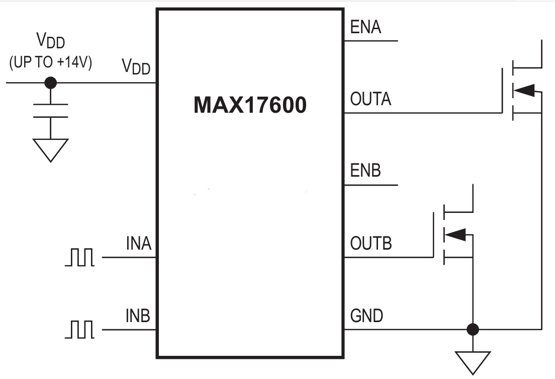
The MAX17600–MAX17605 devices are high-speed MOSFET drivers capable of sinking /sourcing 4A peak currents. The devices have various inverting and noninverting part options that provide greater flexibility in controlling the MOSFET. The devices have internal logic circuitry that prevents shoot-through during output-state changes. The logic inputs are protected against voltage spikes up to +14V, regardless of VDD voltage. Propagation delay time is minimized and matched between the dual channels. The devices have very fast switching time, combined with short propagation delays (12ns typ), making them ideal for high-frequency circuits. The devices operate from a +4V to +14V single power supply and typically consume 1mA of supply current. The MAX17600/MAX17601 have standard TTL input logic levels, while the MAX17603 /MAX17604/MAX17605 have CMOS-like high-noise margin (HNM) input logic levels. The MAX17600/MAX17603 are dual inverting input drivers, the MAX17601/MAX17604 are dual noninverting input drivers, and the MAX17602/MAX17605 devices have one noninverting and one inverting input. These devices are provided with enable pins (ENA, ENB) for better control of driver operation.
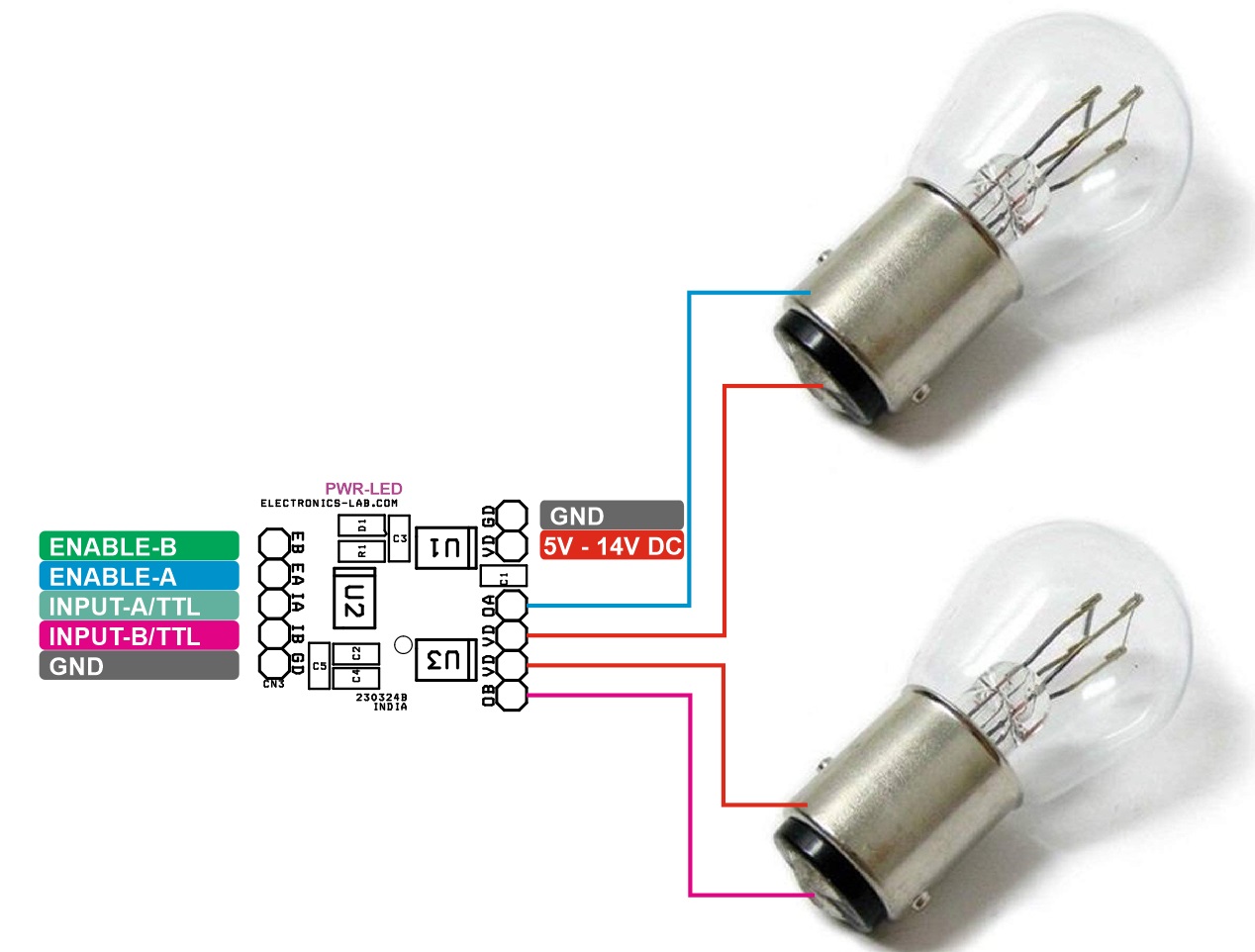
Connections
- CN1: Pin 1 = VDD, Pin 2 = GND
- CN2: Pin 1 = VDD, Pin 2 = Output A
- CN3: Pin 1 = Enable B, Pin 2 Enable A, Pin 3 = Input A, Pin 4 = Input B, Input = GND
- CN4: Pin 1 = VDD, Pin 2 = Output B
- D1: Power LED
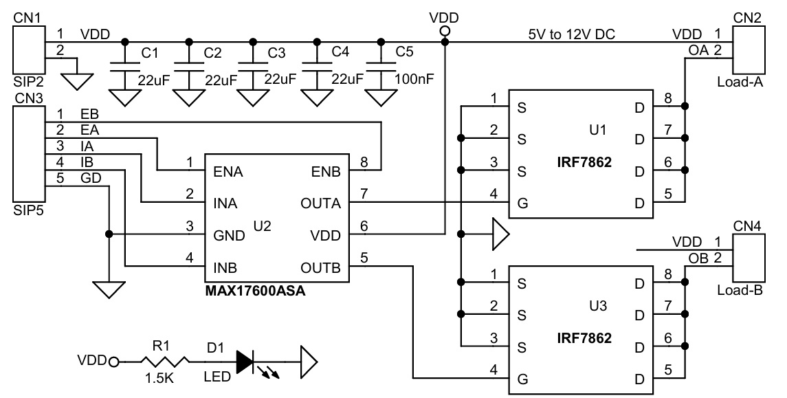
Typical Schematic
Schematic
Parts List
| NO | QNTY. | REF. | DESC | MANUFACTURER | SUPPLIER | SUPPLIER PART NO |
|---|---|---|---|---|---|---|
| 1 | 3 | CN1,CN2,CN4 | 2 PIN MALE HEADER PITCH 2.54MM | WURTH | DIGIKEY | 732-5315-ND |
| 2 | 1 | CN3 | 5 PIN MALE HEADER PITCH 2.54MM | WURTH | DIGIKEY | 732-5318-ND |
| 3 | 4 | C1,C2,C3,C4 | 22uF/25V CERAMIC SMD SIZE 0805 | WURTH | DIGIKEY | |
| 4 | 1 | C5 | 100nF/50V CERAMIC SMD SIZE 0805 | WURTH | DIGIKEY | |
| 5 | 1 | D1 | LED SMD RED SIZE 0805 | OSRAM | DIGIKEY | 475-1278-1-ND |
| 6 | 1 | R1 | 1.5K 5% SMD SIZE 0805 | WURTH | DIGIKEY | |
| 7 | 2 | U1,U3 | IRF7862 MOSFET SOIC8 | INFINEON | DIGIKEY | IRF7862TRPBFCT-ND |
| 7 | 1 | U2 | MAX17600ASA SOIC8 | ANALOG DEVICE | DIGIKEY | MAX17600ASA+-ND |
Connections
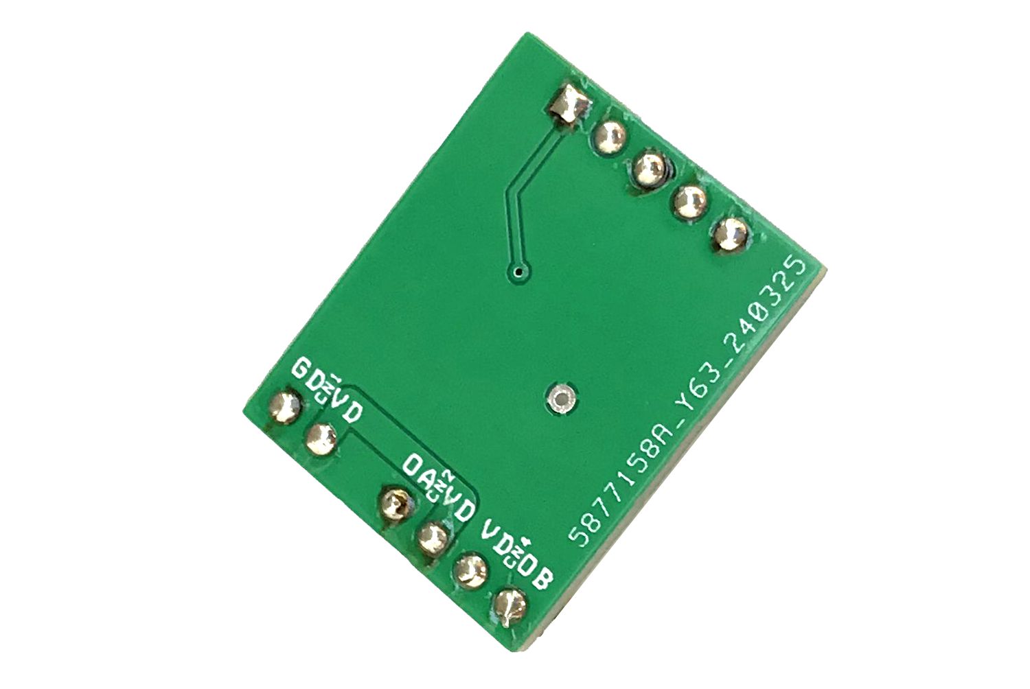
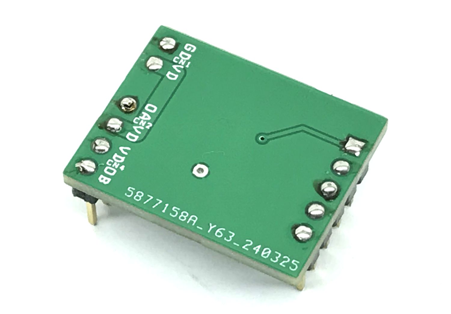
Gerber View
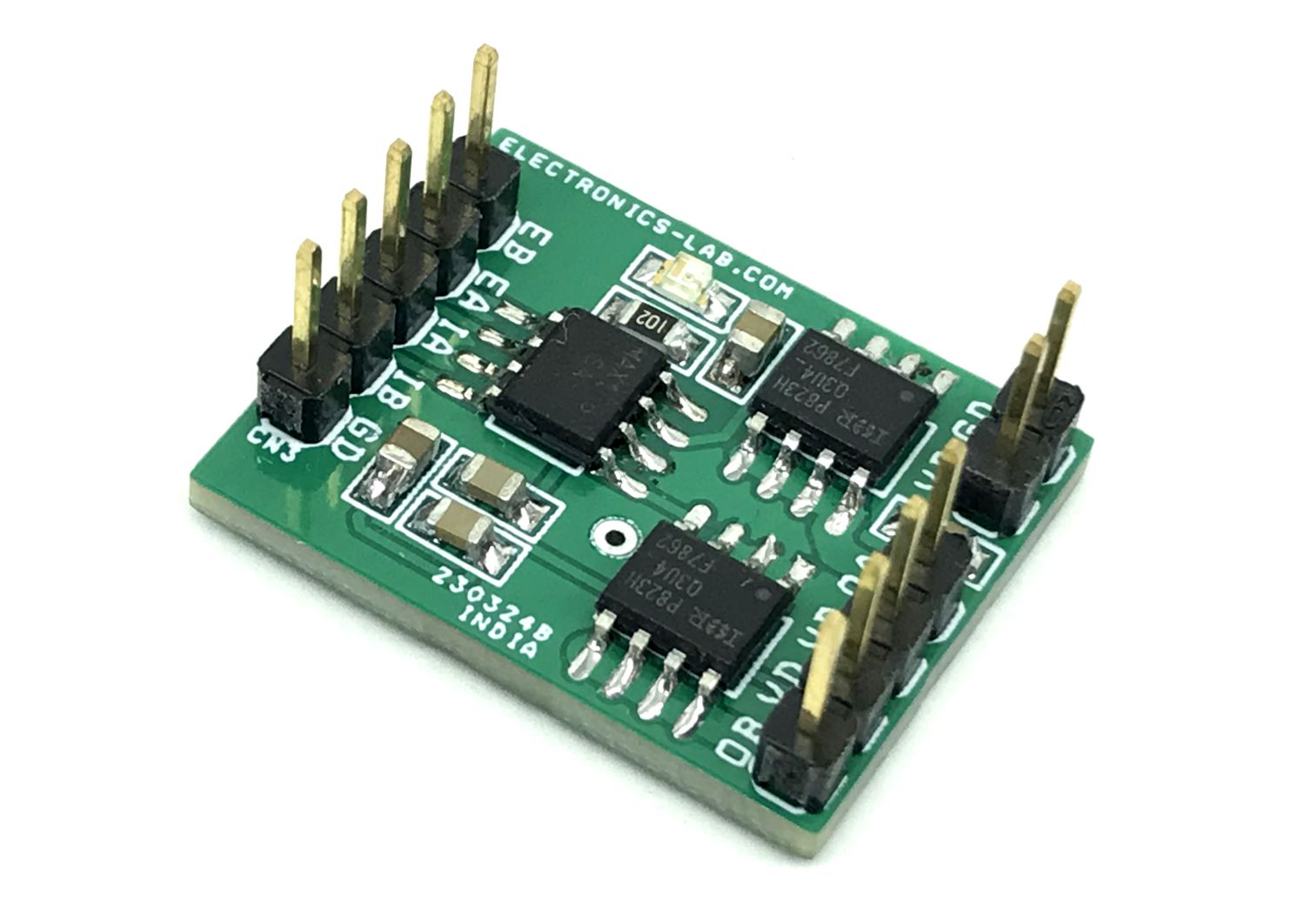
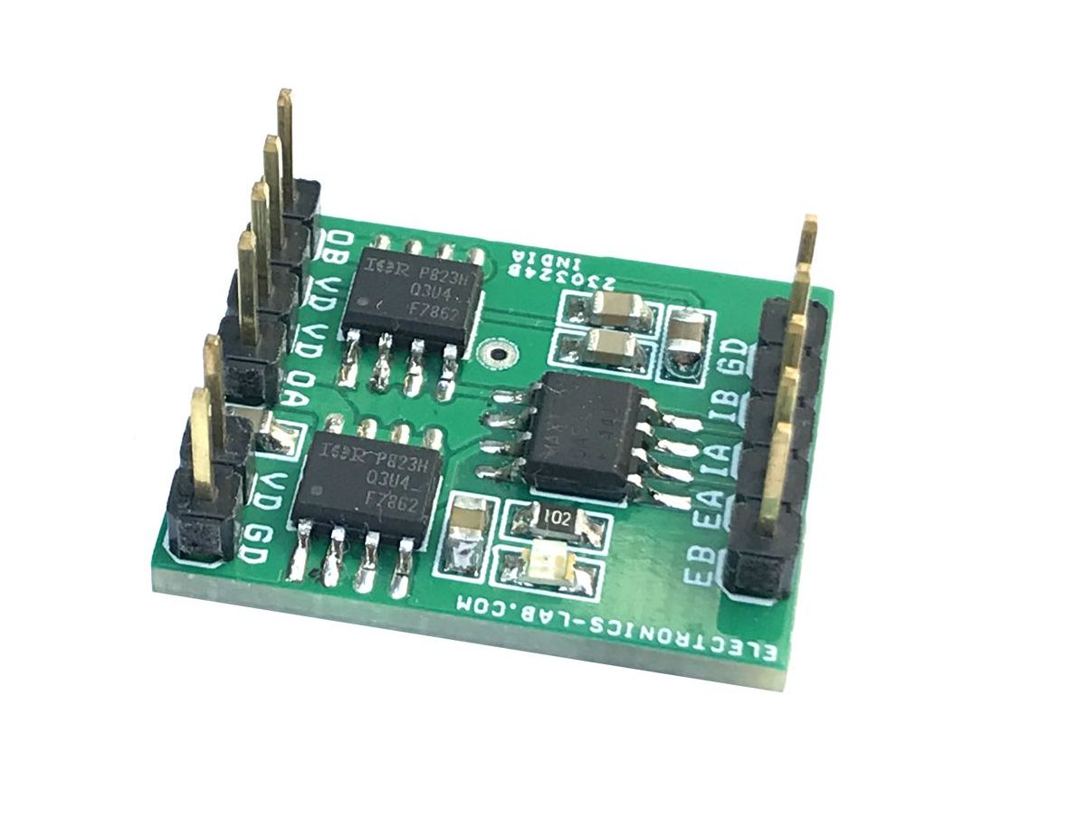
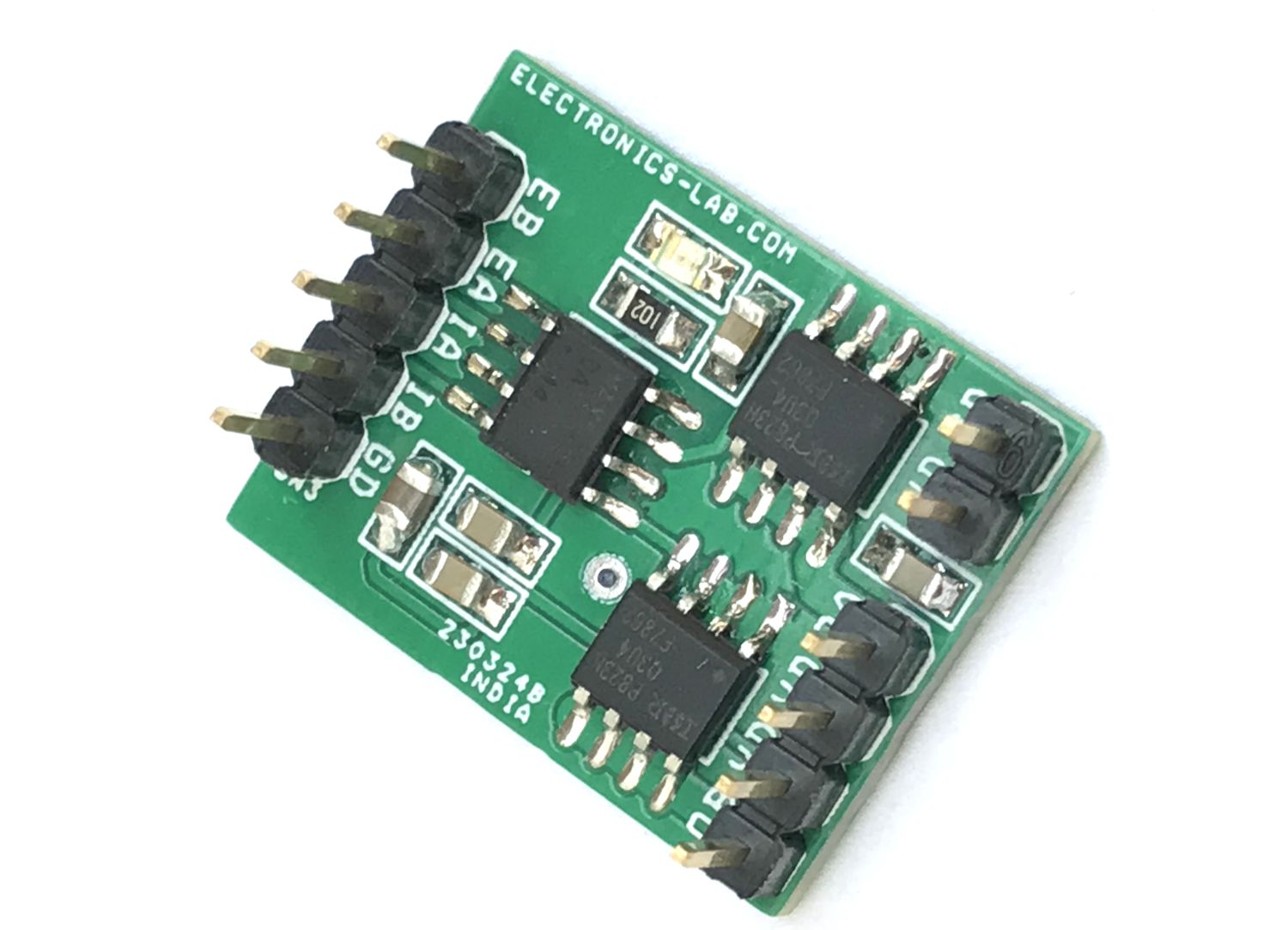
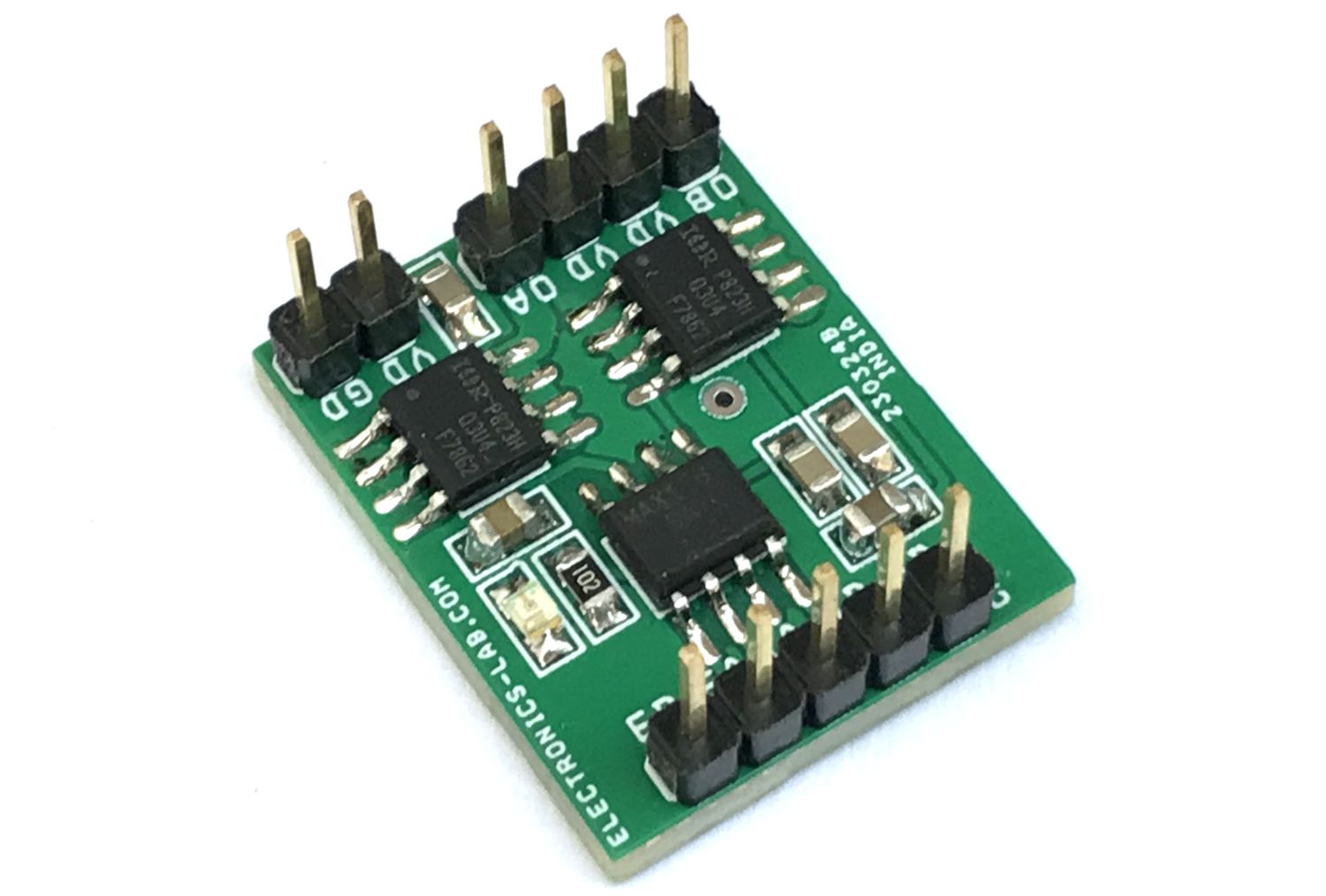
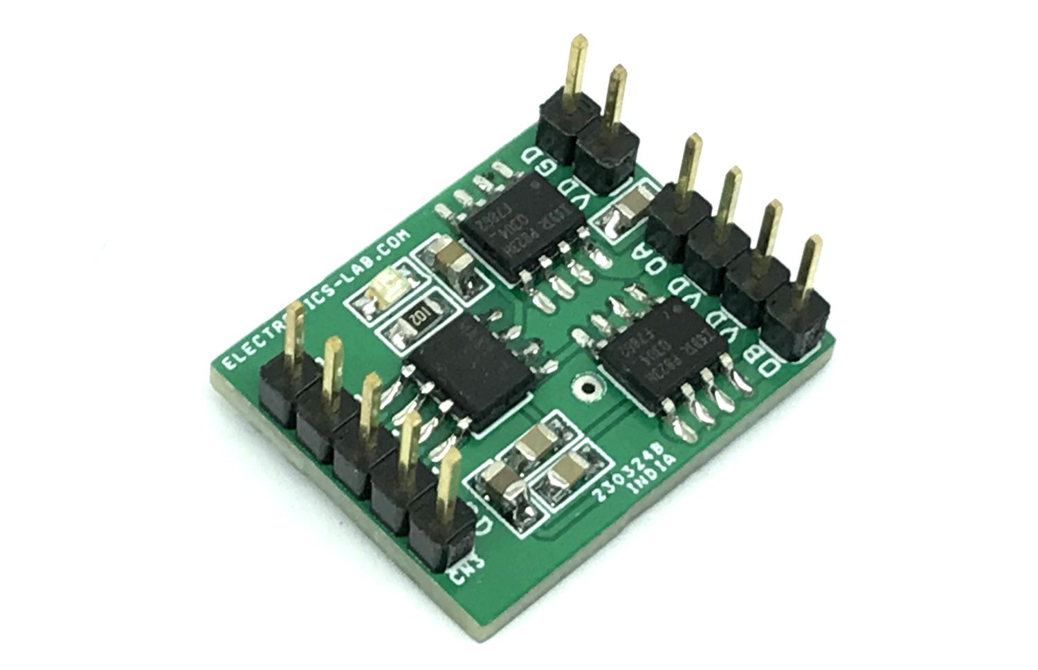
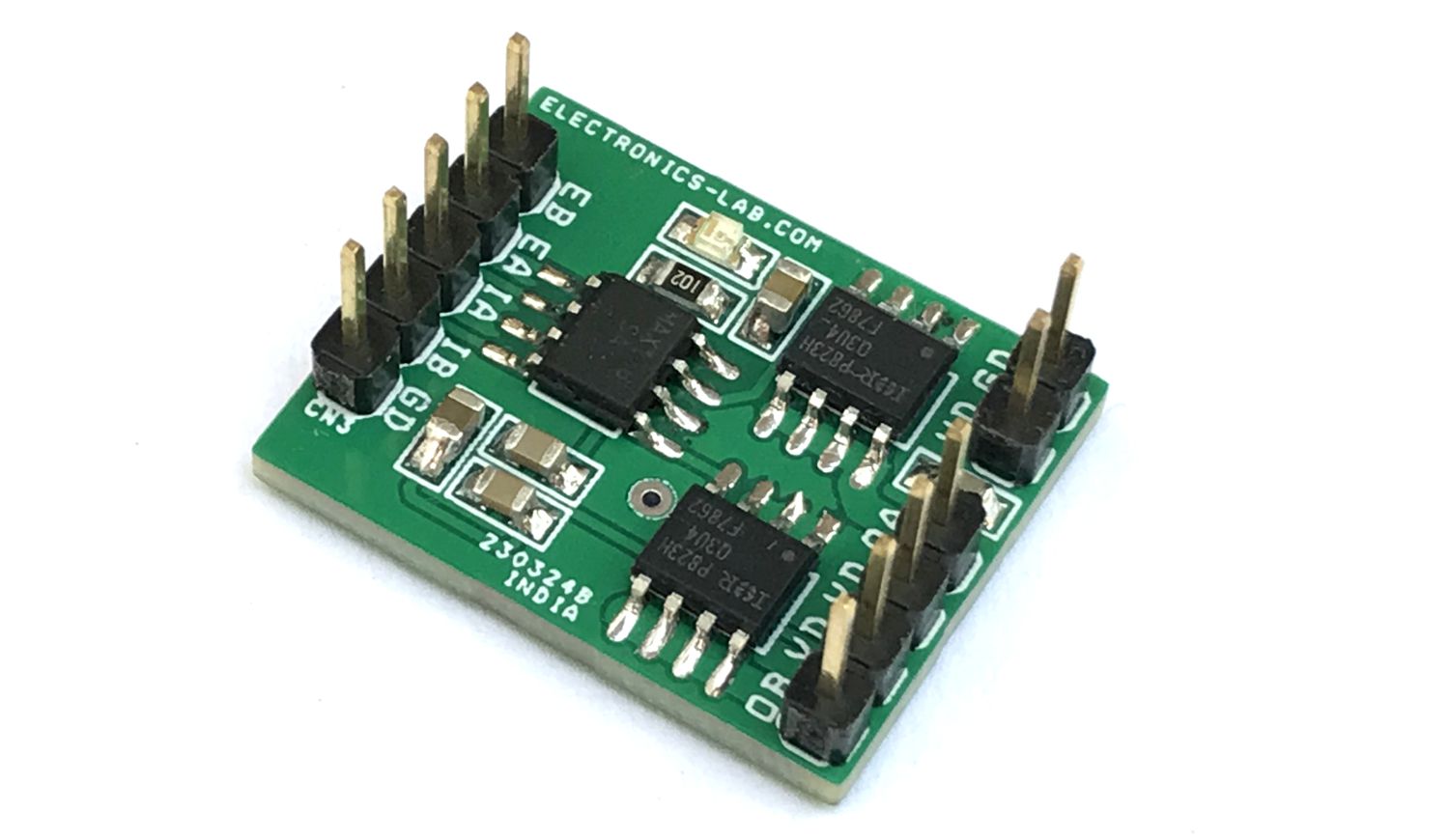
Photos