Current Sensor Amplifier & Over Current Switch
This current sensor amplifier and over current switch project is based on ACS714-30A current sensor and LM358 OPAMP, ½ of LM358 op-amp used as an amplifier for low voltage and 2nd 1/2 LM358 op-amp used as a comparator which provides over current TTL output, trimmer potentiometer provided to set the over current limit. ACS714 sensor measures the current up to +/-30Amps, the final output of the amplifier is 235mV/1A, and normally over current output is High-TTL.
This current sensor amplifier and over current switch project is based on ACS714-30A current sensor and LM358 OPAMP, ½ of LM358 op-amp used as an amplifier for low voltage and 2nd 1/2 LM358 op-amp used as a comparator which provides over current TTL output, trimmer potentiometer provided to set the over current limit. ACS714 sensor measures the current up to +/-30Amps, the final output of the amplifier is 235mV/1A, and normally over current output is High-TTL. It goes low once the current overshoot than a set point. The circuit requires 5V DC and 40mA, and the onboard LED indicates the power. Resistor divider R1, R3 provides bus voltage output for a microcontroller interface to measure the bus voltage, choose the appropriate value for R3, R1 as per your application and bus voltage, it should be less than 5V DC.
ACS714 Current Sensor
The Allegro™ ACS714 provides economical and precise solutions for AC or DC current sensing in automotive systems. The device package allows for easy implementation by the customer. Typical applications include motor control, load detection and management, switch-mode power supplies, and overcurrent fault protection. The device consists of a precise, low-offset, linear Hall circuit with a copper conduction path located near the surface of the die. Applied current flowing through this copper conduction path generates a magnetic field which the Hall IC converts into a proportional voltage. Device accuracy is optimized through the close proximity of the magnetic signal to the Hall transducer. A precise, proportional voltage is provided by the low-offset, chopper-stabilized BiCMOS Hall IC, which is programmed for accuracy after packaging. The output of the device has a positive slope (>VIOUT(Q)) when an increasing current flows through the primary copper conduction path (from pins 1 and 2, to pins 3 and 4), which is the path used for current sampling. The internal resistance of this conductive path is 1.2 mΩ typical, providing low power loss. The thickness of the copper conductor allows survival of the device at up to 5× overcurrent conditions.
Features
- Supply 5V DC
- ACS714-30 low noise direct output 66mV/Amp
- LM358 Amplifier Output 235mV/Amp
- Over Current Output (Normally High-TTL Goes low at overcurrent set point)
- Trimmer Preset to set the Overcurrent limit
- Bus voltage output
- Power LED
- Screw Terminal for Current
- Header Connector for outputs and supply
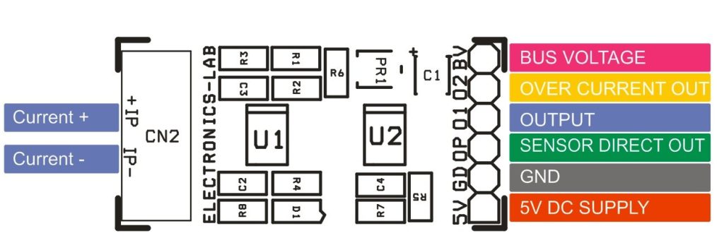
Header Connector Connections
- Pin 1 : VCC 5V DC Supply
- Pin 2 : Supply GND
- Pin 3 : VOP- ACS715-30 Sensor Direct Output 66mV/Amp
- Pin 4 : OP1- Amplifier Output 235mV/amp
- Pin 5 : OP2 Over Current Output ( Normally High-TTL, Goes Low at Over Limit)
- Pin 6 : BSV- Bus Voltage Output
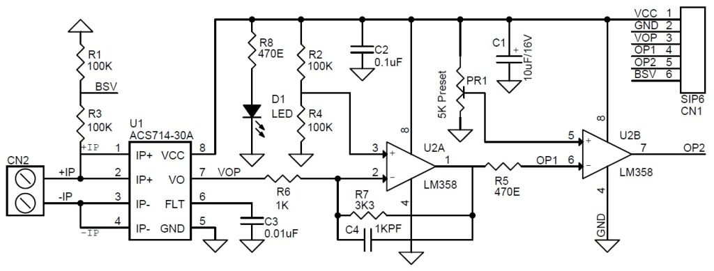
Schematic
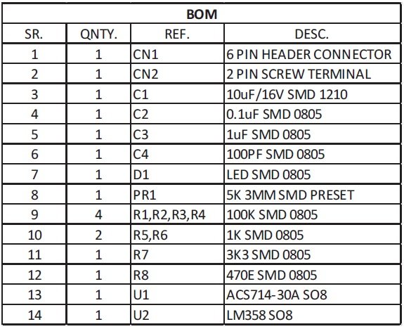
Parts List
Connections
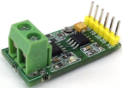
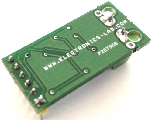
PCB Photo
Sir
How Can we used it to measure low current (less than 50mA) please help
Vop will increase 235mV per A measured, so for 1mA the output should be 235uA which is below the noise of 7mV for this IC. You probably need to look for another solution for such low current.
Is there any place we can order the PCB and parts for the current sensor and over current switch project?
We provide the Gerber files to manufacture your own PCBs and you can order the parts from any distributor online. We can also manufacture this for you if order is >25 boards.
If we swap the inputs to OP2 will the OP2 output go high when current exceeds set point? We need to drive a relay closed when current exceeds set point. Can you make two channel board with two relays Low load on relay contacts – for logic only. We need to monitor two loads with switching at about 180-200 ma. Best if all can run on 24 VDC.
No this will not work like this. If you want to have High output when current exceeds set point, then you need some kind of logic inverter, so the output works in the opposite logic.
I want to control a triac by an optocuplor. When being a short current, triac is broken. Can i use this circuit to protect the triac against a short current?
Hi
Current < SetPoint = OutputLogic H
Current > SetPoint = OutputLogic L
is this correct ?
if U2B 5pin set to 2V, U2B 6pin is 2.5V (zero current), OUT is Low.
and
Higher Current –> Lower U2B 6pin Voltage.
and
if U2B 6pin goes to lower than 2V, OUT is High.
I would like to use this to meassure the current at 24v DC and provide an output ( relay) if the current is higher than a configurable value . Would this work ? What changes required .