

High Voltage-Current Half Bridge Driver Using IR2153 & IGBT
- Rajkumar Sharma
- 82.971 Views
- medium
- Tested
- SKU: EL67449
- Quote Now
- 0 Likes

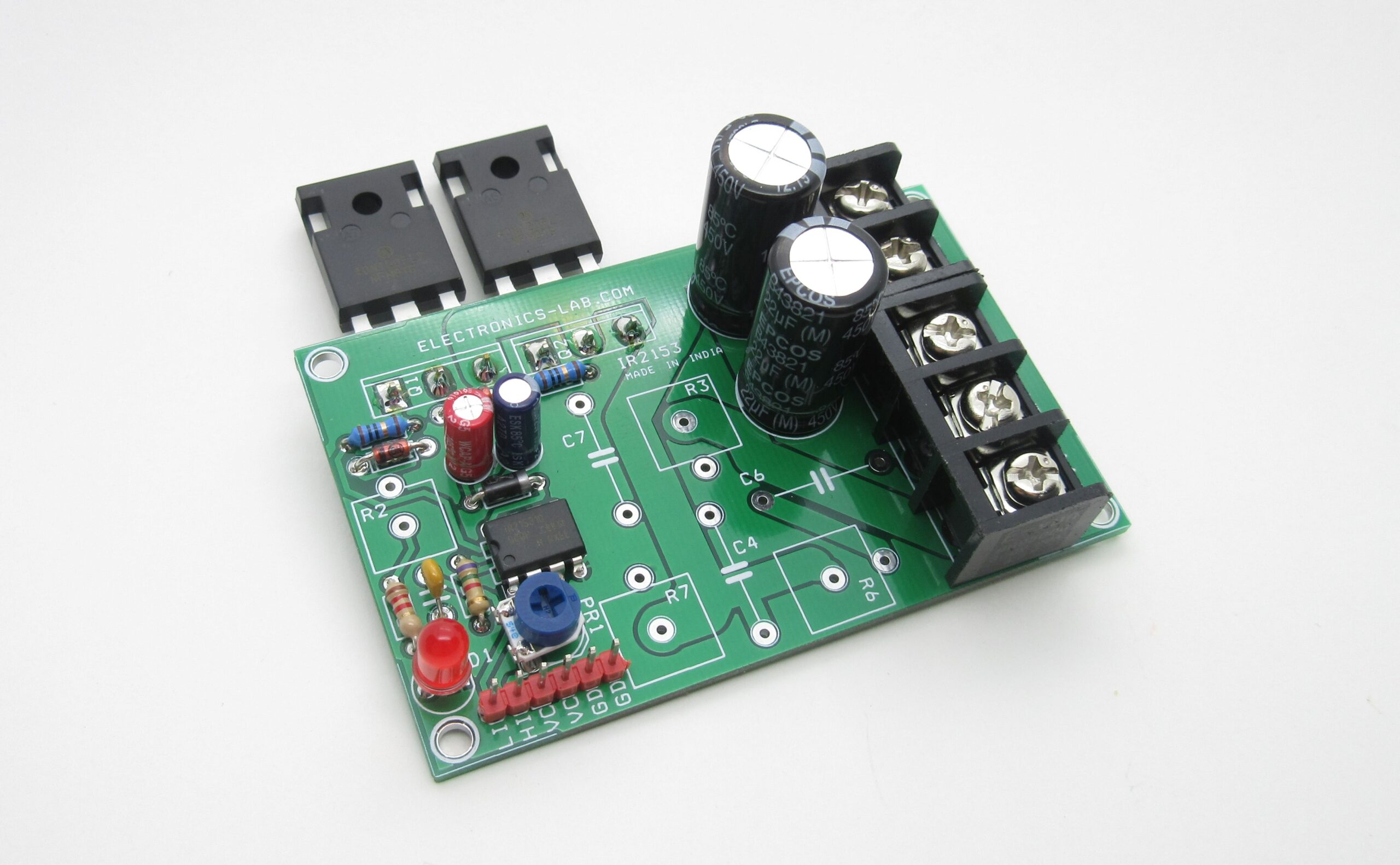
This is an IGBT based half bridge board that has been designed for multiple applications, like Induction Heater driver, Tesla coil driver, DC-DC converters, SMPS etc. High current and high voltage IGBTs are used to serve high power requirements. Its a general purpose Half-bridge board with inbuilt oscillator and it can be configured with many combinations of components, depending on the application requirements.
IGBT NGTB40N120FL2WG from ON semi and IR2153 from Infineon semiconductor are important parts of the circuit, IR2153 is a gate driver IC including an inbuilt oscillator and 40A/1200V IGBT can handle the large current. The Gate driver circuit works with 15V DC and load supply 60V DC to 400V DC.
The IR2153D(S) is an improved version of the popular IR2155 and IR2151 gate driver ICs, and incorporate a high voltage half-bridge gate driver with a front end oscillator similar to the industry standard CMO 555 timer. The IR2153 provides more functionality and is easier to use than previous ICs. A shutdown feature has been designed into the CT pin so that both gate driver outputs can be disabled using a low voltage control signal. In addition, the gate driver output pulse widths are the same once the rising under-voltage lockout threshold on VCC has been reached, resulting in a more stable profile of frequency vs time at startup. Noise immunity has been improved significantly, both by lowering the peak di/dt of the gate drivers, and by increasing the under-voltage lockout hysteresis to 1V. Finally, special attention has been played to maximizing the latch immunity of the device and providing comprehensive ESD protection on all pins.
Power Supply Considerations
The board has two power options for the input supply, so users can choose the input load power supply as per application requirement:
- Load Power Supply 60-400V DC
- Logic Supply 15V DC for Gate Driver
In case you want to use 230V AC mains power supply as power input it is advisable to use this power supply board that provides 330V DC after rectifier + filter Capacitor. Then the IGBT board will work with single supply (no logic supply required) by soldering one resistor R2 33K Ohms 5W and replace capacitor C3 with 470uF/25V
If you use another isolated High Voltage DC power supply, then omit R2 and use an external 15Vdc logic supply.
The oscillation frequency is adjustable by onboard trimmer potentiometer and frequency spans approx. 12 KHz to 100 KHz with duty cycle 50%.
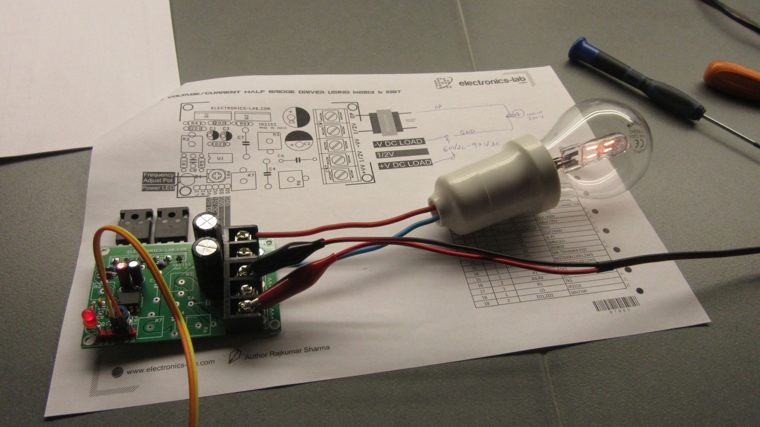
Testing
We have tested this board up to 500mA/330V DC without a heatsink, if more power is required you should use a heatsink and a fan.
If you wish to test this board with a Tesla Coil its advisable to use a series lamp of 100W at AC input. This will prevent an overload condition when you test the board.
400V – 5A Power Supply For Brushless Motor Drivers is a suitable power supply for this driver.
Notes
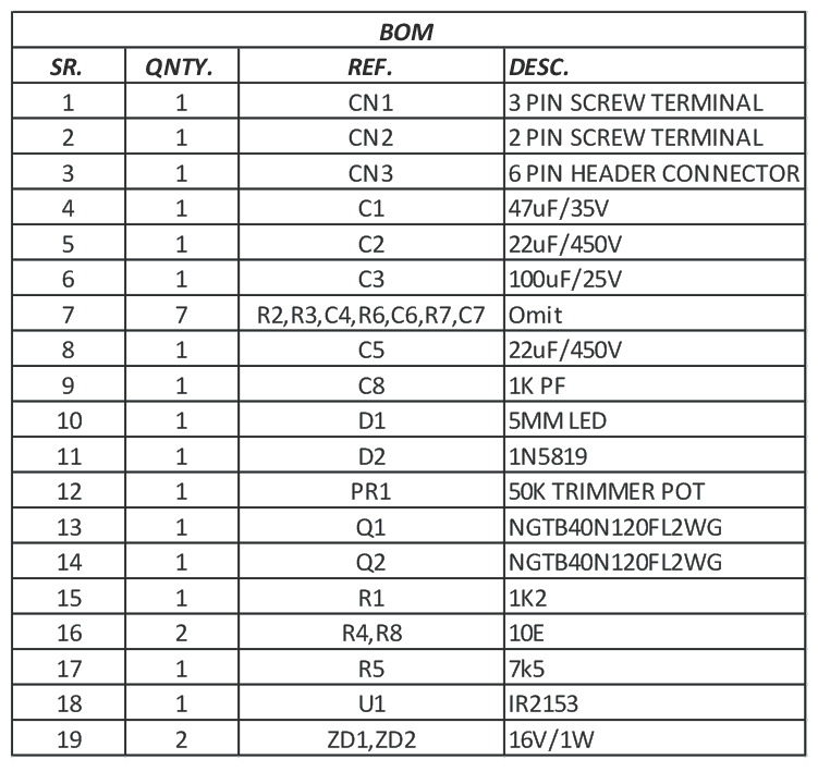
- Note 1: The circuit is provided with few extra components which may be used as per application requirement other components can be omitted as stated in BOM
- Note 2: Frequency span is determined by CT Capacitor (C8) and Trimmer Pot value, refer to the datasheet for the appropriate value for the required frequency span. C8 1Kpf, R5=7k5, and PR1=50K provide frequency span 12 kHz to 100 kHz.
- Note 3: Other MOSFETs or IGBT can be used as per your current and voltage requirements
- Note 4: This board can also be used as half-bridge using IR2101 and MOSFET with High PWM Pulse and Low PWM Pulse input or IR2104 with a single PWM pulse. Header CN3 provides input Pin1 HIN and Pin2 LIN for that purpose. Omit the following components R5, PR1, C8 to use with IR2101/IR2105.
- Note 5: IGBTs require large size heat sink.
Features
- Load Supply 60V to 400V DC
- Gate Driver Supply 15V DC
- Frequency Span 12 KHz to 100 KHz, Other frequency range possible by changing R5, PR1, C8
- Duty Cycle Approx. 50%
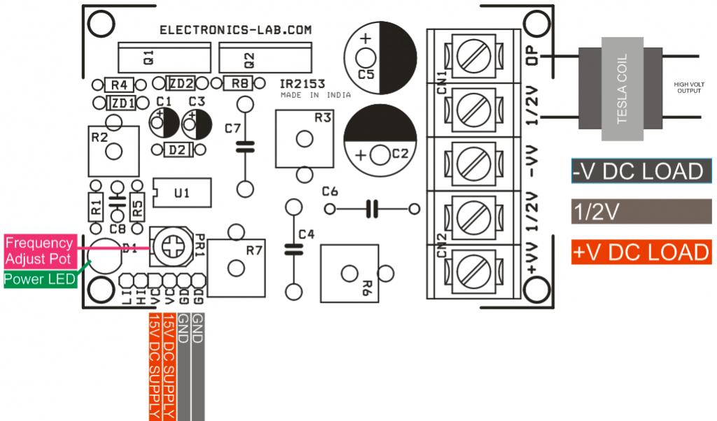
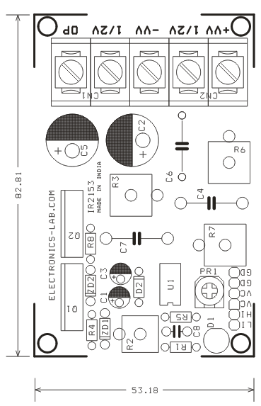
- PR1: Trimmer Potentiometer to set the frequency
- CN3: Logic Supply 15V DC
- CN1: Supply DC Input
- CN2 : L1 Load
Applications
- Tesla Coil Driver
- Induction Cooker
- Induction Heater Driver
- DC-DC Converter
- DC to AC Converter
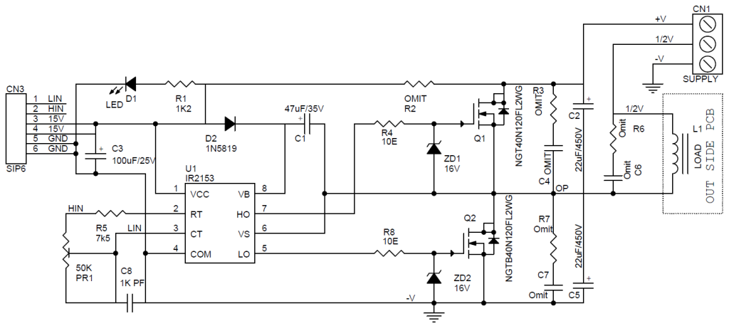
Schematic
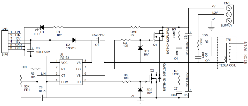
Tesla Coil Example
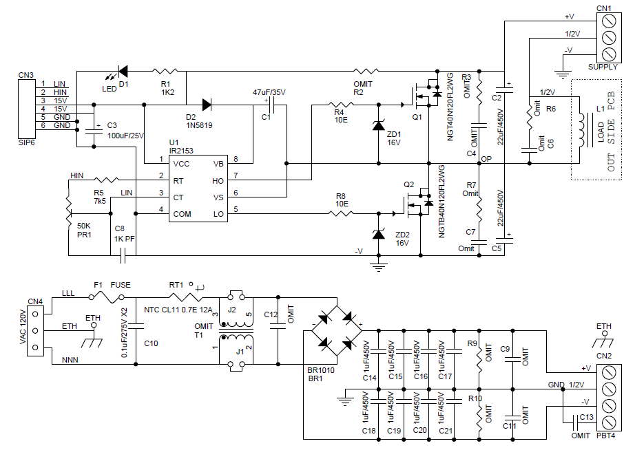
Schematic with PSU
Parts List
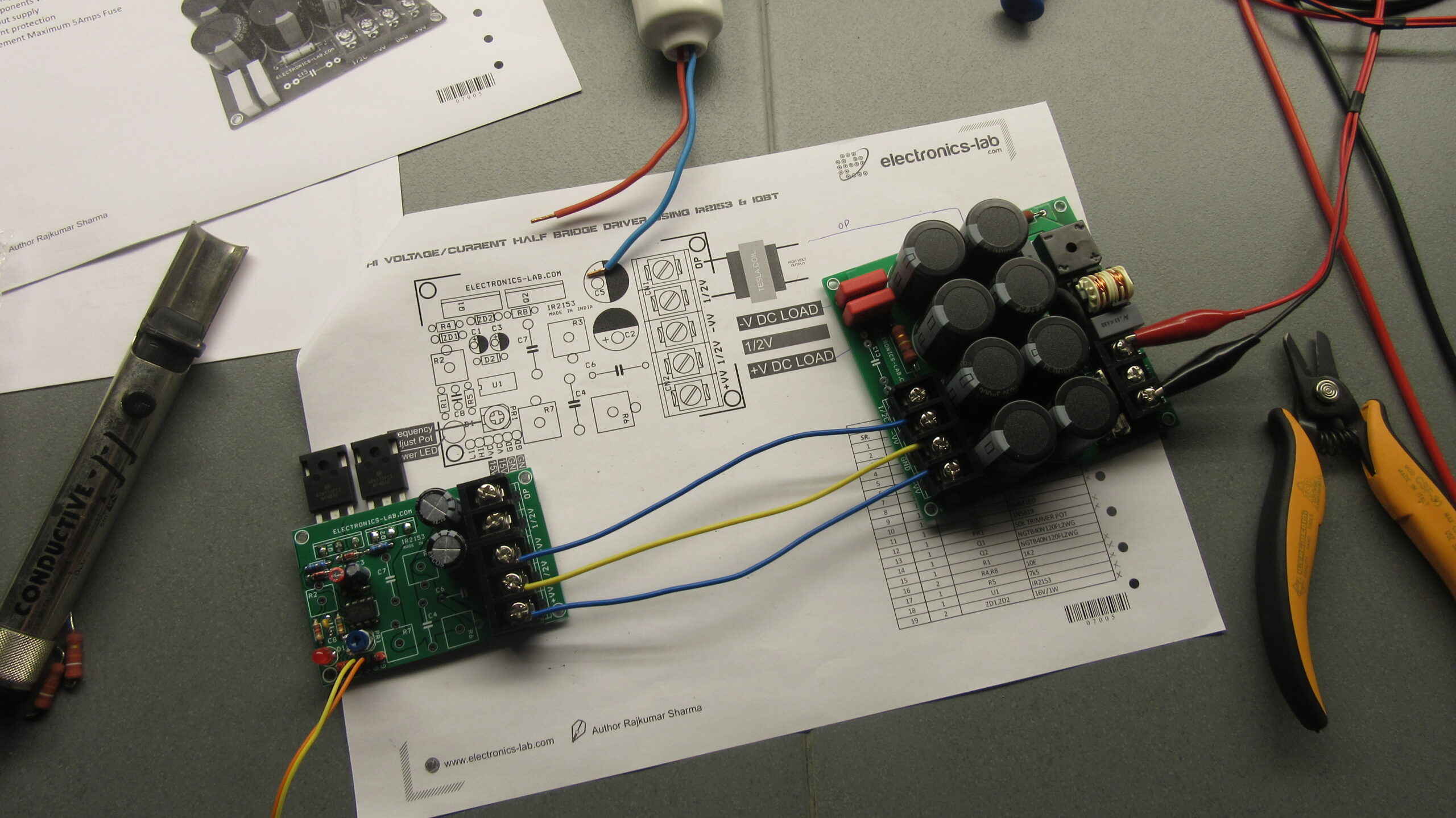
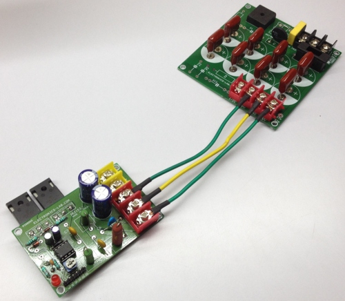
Connections
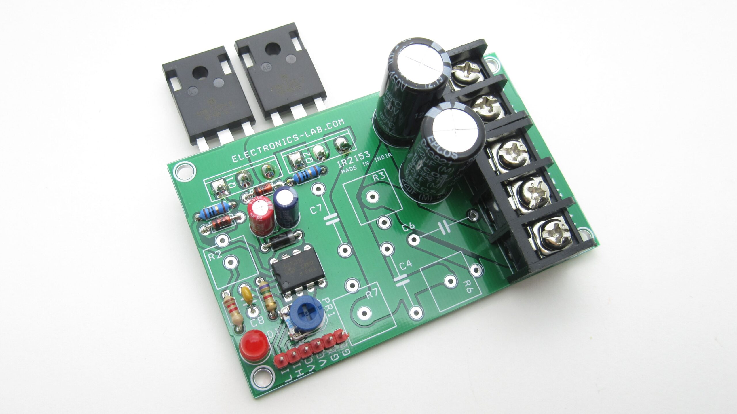
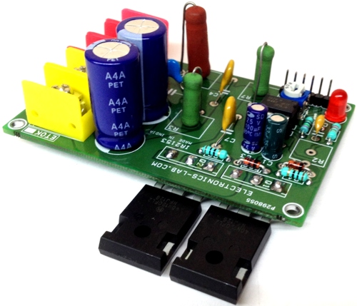
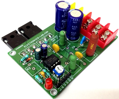
Photos

Videos
IR2153 Datasheet
IR2101/IR2102 Datasheet
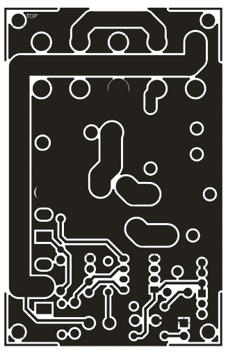
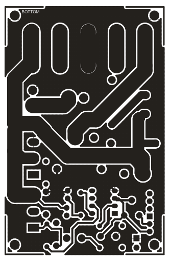
PCB


Could you advice about Omit part list?
R2,3,6,7
C4,6,7
How to calculate it?
Thank you.
There is no need to place those components. You can discard them.
Dear I need this Circuit 2Pcs. Kindly give me contact details.
We can manufacture this project for you if order quantity is >25 pieces. Otherwise you should build it your self.
My customer need only 2 pieces for test. If OK then I will buy as your MOQ.
We are able to sell 2 pieces. Please use the contact form above to email us.
Dear I can’t see your contact. Could you send email to idriskaka@gmail.com
Thanks
Please use the contact form from the top menu. I tried to email you, but no luck.
Hello. Please send me a price for 2 pcs.
Mail: lehel2002@yahoo.com
Thanks!
Thanks
Dear sir,
I need 6 kw induction heater board with heater coil. It has to be work directly. No need time setting. Output frequency is 15-20 khz. İnput 220 vac 50hz monophase. This system has to heat 80 litres water fastly. (The water is turning continiously via circulation pump with pipe (steel). 5 C to 80 C.
Can you supply this sysems for me or have you any suggestion. İf you can please quote the price.
Regards.
I am also interested at such a develope! Have you any infos of realisation?
We can produce this on order. Our minimum order for this is 10 pieces.
Nice person. Thanks
Hallo, can you infotm me, where i can buy assembled moduls?
Robert
I left a message 2 months ago and had no response. I have seen other posts on the site and they do not really supply kits. They might supply blank boards but no one responds to this page. Mark
We may miss your message, what’s your need now?
Hello Mike
I posted a list of questions re: the circuit Can you respond there?
I am not able to answer these specific questions. Please wait if someone else can.
OK Thank you Mike
Hie Admin. Thank you so much for the post.
I wish to know how I can modify the circuit so that I use it for halfbridge resonant inverter for a domestic induction cooker, and how I can incorporate a microcontroller like arduino for the control and power level adjustments.
We have other Half-Bridge projects here:
https://www.electronics-lab.com/project/high-current-discrete-half-bridge-based-ir2104-ir2101/
https://www.electronics-lab.com/project/high-voltage-current-half-bridge-driver-using-ir2153-igbt/
https://www.electronics-lab.com/project/half-bridge-driver-based-on-ir2104/
For technical support please use the community: https://www.electronics-lab.com/community/
Hello Mike,
How much for 25 pieces sent to Canada?
Please email us using the contact form above.
what is 1/2V?
1/2V is basivally the GND reference for the output voltages.
A bit vague the answer. please be more explicit, possibly by example! I built the circuit and want to use it for a Tesla coil powered at a voltage around 48 V DC, from a switching source. Do I connect + to +, – to – and how do I output to TC?
The Tesla Coil picture shows a Transformer TR1. This is a flyback transformer that you can purchase here https://www.amazing1.com/transformers-high-voltage-high-frequency.html That site shows a similar schematic and notes on how to wind the primary. Be very careful there is a lot of power going into the transformer. I am building this circuit and when I power it up I am planning to use a variac to bring up the supply voltage carefully so I dont burn out the IGBTs or the transformer.
Hi, EL-team,
may I get this 1µ 450v caps from you?
Are they usable up to 300 kc ?
If 2 times yes, which procedere, which price for 10 pcs?
*HAGT*
Teslator
The capacitor you mention is 22uF/450V, is that what you need?
“OMIT” stands for open circuit or short circuit?
Thank you
OMIT means you don’t need to place that part, so open circuit.
Omit with shortcircuit or open?
Check for answer above.
What about the Hin and Lin
The voltage range,wave form and relation between Hin and Lin
The Hin and Lin are PWM signals to drive high side MOSFET and low side MOSFET in case you want to use IR2101 and MOSFET. Check page 5 of IR2101/IR2102 Datasheet embedded above for timing diagrams.
Greetings, currently i am developing an induction heating system based on your design.
The components that you mention to omit, are from a snubber, right ?, because it seems that in my application if it is required.
In other order of ideas, in wich program did you develop the pcb? The design is very good, but it is small and because the double layer is difficult to weld. Thanks
Yes, it’s a snubber circuit used to eliminate voltage spikes as the switches goes ON and OFF. It is recommended to be implemented on inductance load. The PCB is developed in Cadece OrCAD and 2 x layers where used to keep overall PCB complexity and size at minimum. If you need a single layer design you will have to design something from scratch.
Hi everyone !
Is this driver IR2153 capable to charge and discharge the gates of IGBT NGTB40N120FL2WG without totem pole transistor ?
I mean those IGBT have over 7nF input capacitance.
Yep, that’s the purpose of driver IC IR2153D. This is designed for IGBTs and MOSFETs.
Hi !
Would you please share the values for snubber circuit; omitted resistors and capacitors ?
I intend to drive inductive load – ferrite core. Expected primary current is up to 10A.
In addition would you please suggest other changes, since my input voltage will be up to +-30V only , oscillator set to 20kHz ? Thank you !
a typical snubber circuit would be 4R7 4W resistor and 4n7 1kV capacitor
Hello Mike
Q1 – RE: filter caps on power supply – The 400V 5A PS circuit uses 4 x 220 uf 880 /side and the tesla coil PS uses 4 x 1uf caps 4uf/side. Is the reason the Tesla coil does not need as much filtering? Does this effect the current drive to the coil ?
Q2 – Re: Output voltage calculation of power supply – The circuit is 2 full wave rectifier creating a virtual ground. Isn’t the peak voltage 1.414*120 VAC *2 =~ 339 V peak. The filtered voltage being lower? So is the voltage using 220 VAC input 1.414 * 220VAC * 2 = 622 V peak. Can you explain the 400 Volt rating?
Q2 – Re: Power control : I have seen an example of the half bridge driver using a PWM connected to Pin 3 (LIN) to control the power output. Have you ever tried power control using pwm to the output?
Q3 – Re: Resonance : To tune a particular system for resonance is the primary coil impedance the main inductance and the secondary load not a factor?
Q4 -Re: Resonance 2 : Is the 22u caps the capacitance resonance?
Thanks in advance
Mark
I am still interested in the answers to the above question
Hi I need directions. I’m trying to build a speed controller for my electric bike the igbt pack for switching keeps confusing me pls I need directions. Thanks
Hi,
Required 25 number of PCB(P298055) of the above schematic .
Kindly let me know the price.
also the lead time to supply to India,Bangalore.
With Regards
Poornachandra
Dear Mike
Can i use this for ozone generator? If yes please suggest me changes for ozone generator. Please give me design of transformer also.
Thanks
NKPatel
Hi, After making the pcb and components assembly, the resistance between +V & -V is found to be 4Ohms with continuous beep in multimeter. I checked all the assembled components, no problem in soldering and assembly. Don’t know whether to proceed with 330VDC source….kindly suggest….
Hai, is it ok to use electrolytic capacitors (C1 & C5) at KHz frequency range?
Hi,
I built a couple of these for a project. I used the Gerber files listed to get the boards made. I had to get a minimum order of 10 units. If anyone is interested in buying a set of these Half Bridge boards only, I will sell them for the cost to me plus postage costs. It cost me AU$ 25 a set. So I reckon that is similar to about US$17.50. You can use paypal if you wish.
I have eventually got around to use these boards in a project. Although the circuit is very comprehensive, I have run out of SCHOTTKY diodes. I have not been able to reconcile the efficiency of this circuit due to not being able to get the half bridge to work. My oscillator board is exactly as the author’s! So I have spent several hours looking for various option. Unfortunately, to me this project is a failure. Somehow I am generating too much current for the SCHOTTKY to handle.
Well, I have ordered new diodes and ir2135 and the IGBT’s. There is a problem with this board when connected to the recommended power board. The oscillator board is working. As soon as the connecting to the power board are made, the IGBT’s, the diode, the gate diodes and the IR2153 are all shot. Looking at the circuit, I could see that this occurrence should not occur! All I can think of is that the boards must be faulty. Somewhere is shorting out. And, I have not progressed past the 60v test with the light globe and power board. I am using a 15 volt dc for oscillator supply and a variac for the powerboard supply. I give up!