Motorcycle Universal Gear Indicator
Introduction This is a new design for a universal gear indicator that can be fitted to any motorcycle as an aftermarket accessory. Its main advantage is that its operation depends entirely on the gear shift lever movement, instead of connecting to speedometer and tachometer sensors (found in expensive commercial devices), which are rarely available in older motorcycles.
Introduction
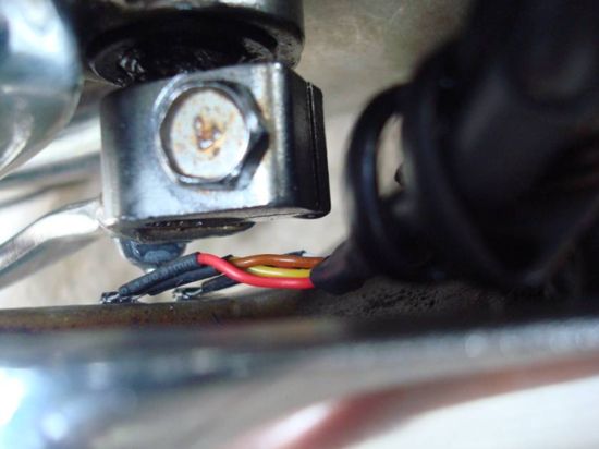
This is a new design for a universal gear indicator that can be fitted to any motorcycle as an aftermarket accessory. Its main advantage is that its operation depends entirely on the gear shift lever movement, instead of connecting to speedometer and tachometer sensors (found in expensive commercial devices), which are rarely available in older motorcycles. It consists of a main circuit including a 7‑segment LED indicator, two Hall sensors that are attached to the motorcycle frame, and a small magnet placed on the gear shift lever.
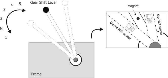
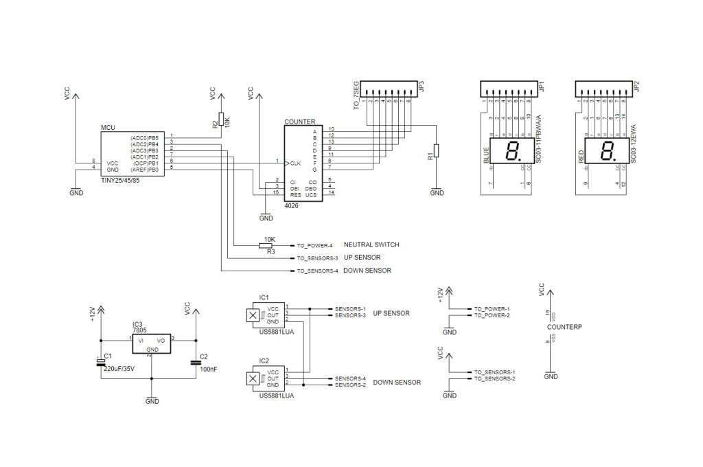
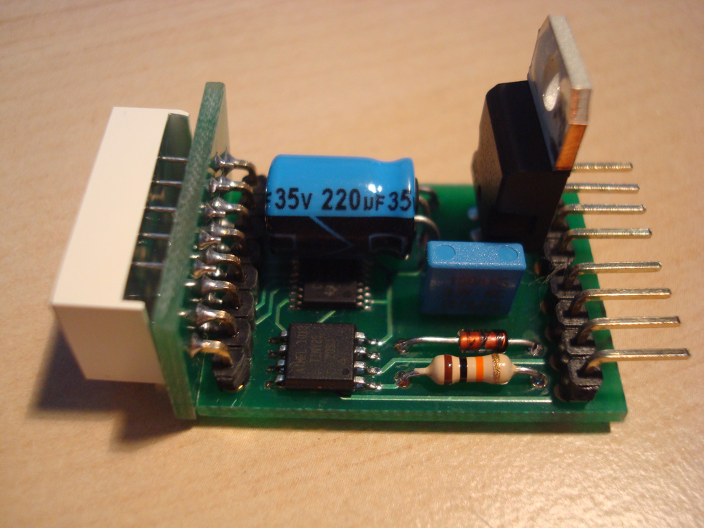
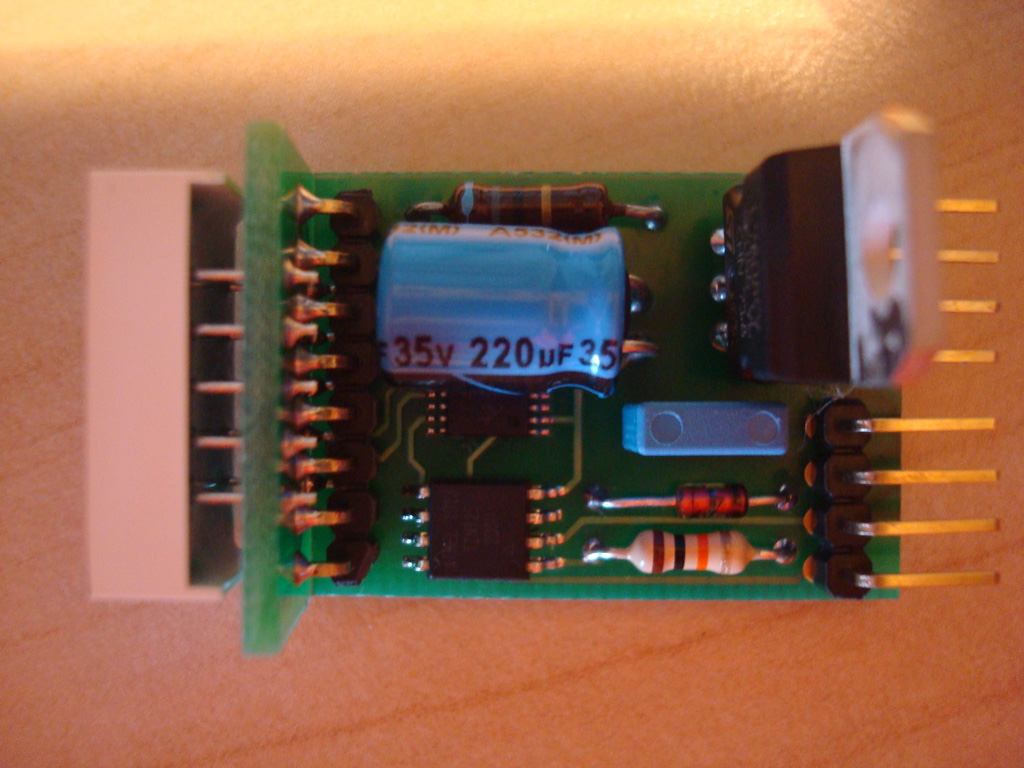
The main circuit is based on an AVR ATTINY25/45/85 microcontroller, which reads the signals of the two Hall sensors and the neutral switch and outputs the current gear number to a 7‑segment LED indicator, through a 4026 counter/decoder.
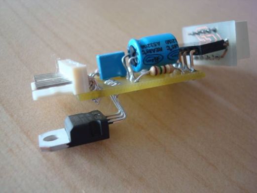
At maximum output power there is significant heat produced by IC1 and for that reason we mounted it directly on the ground plane to achieve maximum heat radiation.
Schematic
Source Code
The source code is written in AVR-GCC (WinAVR) and can be programmed with the default fuses using an AVR programmer (default : ATTINY25 microcontroller and USBTiny programmer). Moreover, the constant TOP_GEAR 5 should be changed to 6 for six-gear motorbikes. Source code can be downloaded on the download section below.
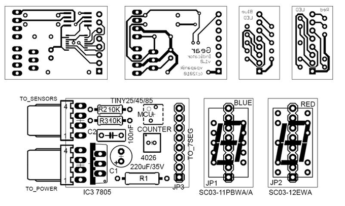
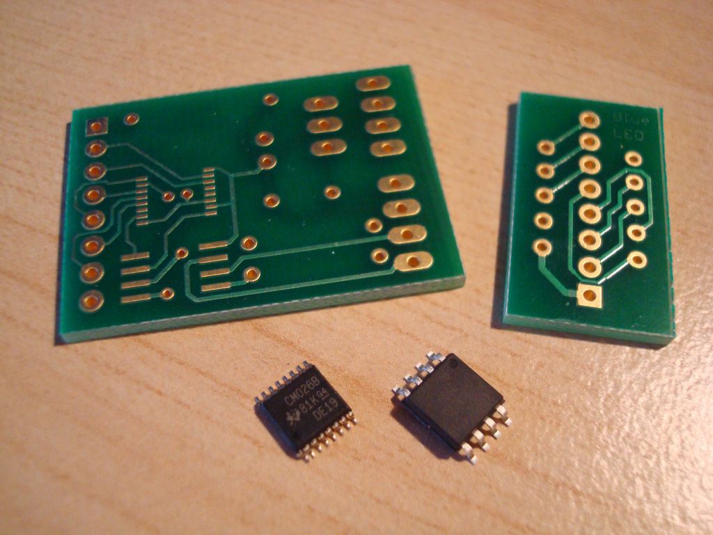
PCB Design
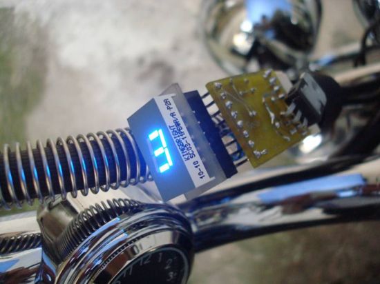
The suggested implementation for the main circuit is a small size, double-sided PCB, with SMD packages for the microcontroller and the decoder ICs. The 7-segment LED is placed in a secondary PCB, connected vertically to the main one in a modular fashion (see pictures). Two PCBs for different Kingbright LED footprints (red and blue) are also provided.
Parts List
| R1 | 10 to 220 Ω ½W | Depending on preferred LED brightness |
| R2, R3 | 10 ΚΩ ¼W | – |
| C1 | 220 μF / 35V | Electrolytic capacitor |
| C2 | 100 nF | MKT/polyester capacitor |
| MCU | ATTINY25/45/85 | Mouser Part 556-ATTINY25-20SU |
| COUNTER | 4026 | Mouser Part 595-CD4026BPWE4 |
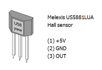
| IC1, IC2 | Hall sensor | Melexis US5881LUA |
| IC3 | 7805 | 5V Regulator TO-220 |
| BLUE | Kingbright 0.3″ | Mouser part 604-SC03-11PBWA/A |
| RED | Kingbright 0.3″ | Mouser part 604-SC03-12EWA |
| JPx | Pin connectors | As shown in silkscreen and pictures |
Possible improvement
In the current design, when the neutral switch is open (there is a gear on), there appears to be a very small current (< 0.5 mA) sinking through R3, due to the voltage difference between the neutral switch connection (TO_POWER-4) and the microcontroller. If the neutral indicator is of LED type (not a resistor bulb), there is a possibility that it stays dimmed, instead of being completely off. In that case, a small switching diode (1N4148) can nicely replace R3 (on the same PCB) in order to block this small incoming current when the neutral switch is open, as shown in the figure below :

For a better insight in the above issue, the following script can be imported in Paul Falstad’s excellent circuit simulator:
http://www.falstad.com/circuit
$ 1 5.0E-6 10.20027730826997 62 5.0 50
R 192 96 192 48 0 0 40.0 5.0 0.0 0.0 0.5
R 512 96 512 48 0 0 40.0 12.0 0.0 0.0 0.5
r 192 96 192 176 0 10000.0
x 231 142 309 145 0 12 internal pullup
x 125 25 277 31 0 24 Gear Indicator
x 456 26 571 32 0 24 Motorcycle
M 192 176 96 176 0 2.0
x 65 157 118 160 0 12 AVR Input
w 192 176 192 256 0
162 512 96 512 160 1 2.1024259 1.0 0.0 0.0
r 512 160 512 256 0 470.0
d 512 320 512 400 1 0.805904783
x 413 388 499 391 0 12 protective diode
s 512 400 640 400 0 1 false
g 640 400 640 448 0
x 539 422 615 425 0 12 neutral switch
x 309 240 391 246 0 24 1N4148
x 132 377 269 380 0 12 in place of R3, and watch
d 304 256 400 256 1 0.805904783
r 304 336 400 336 0 10000.0
x 337 371 367 377 0 24 R3
S 192 320 272 320 0 1 false 0
w 192 256 192 320 0
w 304 256 272 256 0
w 272 256 272 304 0
w 304 336 272 336 0
w 400 256 400 304 0
w 400 304 448 304 0
w 400 336 400 304 0
w 448 304 512 304 0
w 512 304 512 320 0
w 512 304 512 256 0
x 131 359 276 362 0 12 flip switch to insert a diode
x 134 394 272 397 0 12 current drop to zero when
x 134 412 254 415 0 12 neutral switch is open
… or click here for direct Circuit Simulator Link
Contributed by Brett Walach
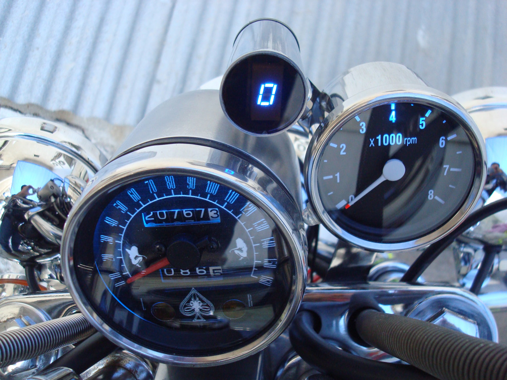
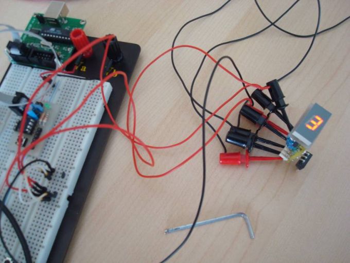
Photos
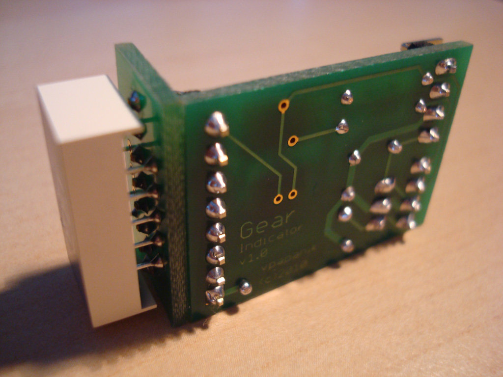
Connections
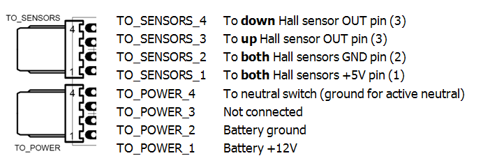
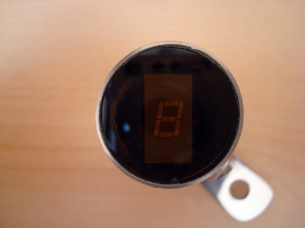
A successful circuit build will do a self-test when connected solely to 12V power (pins TO_POWER_1 and TO_POWER_2), by cycling through all digits on the 7-segment display (see video below). After the self-test, the current gear will be shown and can be changed by the shift lever movement. Note that a gear is changed when the magnet’s south pole is drawn away from the sensor (north pole will not work). Moreover, if a neutral gear is detected (from the neutral switch connected to TO_POWER_4), the display resets to zero (also acting as a self-calibrating feature if anything goes wrong). Finally, when the power is turned off, the last shown gear is stored in the MCU’s flash EEPROM and restored when the device is turned on again.
The following video shows the initialization procedure of the gear indicator :
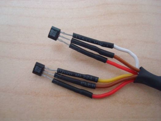
Sensor Cable
The following photos show the construction of the 4-wire sensors cable that is plugged to the TO_SENSORS connector. The visible sensor pin parts should be covered with plastic lacquer for protection as well.

After putting it all together the circuit is now operative and ready to be installed on the motorcycle. A video showing a simulation of gear shifting (by hand) is available below :
Installation Photos
Here are some photos and videos from the installation on my Suzuki Intruder VS400


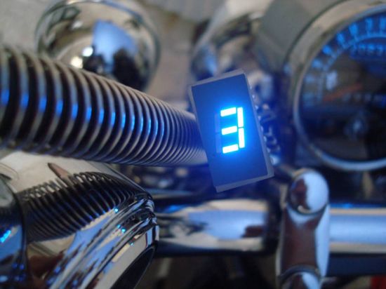
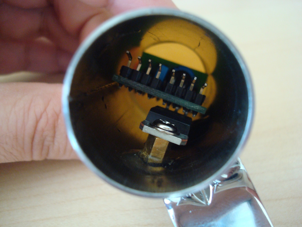
Custom Housing
Installation Videos
Installation1 – Gear shifting by hand
Installation2 – Real gear shifting with engine on
Installation3 – Storing last gear in EEPROM
Thanks for reading !
Designed and built by Vassilis Papanikolaou © 2010
tutorial burning script to mcu ATTINY25….what tools recomend….thanx…sory i’am indonesian
How much would this overall cost the circuit making and the actually product.?
Nice Tutorial. Thank you.
Hello.
How much would the finished product cost if I ordered directly from you ?
We are sorry, we don’t sell kits or assembled products.
Can’t you though? It would be nice.
Nice Project, But i would prefer N instead of the 0 for neutral, could this be written into the source code easily ?.
Thanks for sharing your project.
Thanks for your comments. Unfortunately 7-segment display can’t display the letter “N”, so that’s why they show 0
You can use “H” instead od “0” to indicate Neutral
There is also 17 segment alphanumeric display…
Sorry i meant the letter ‘n’ ie segments A,B,C,E,F ?.
Sorry, i didn’t get you. You can display some letters on a 7-segment display but you have to modify the source code.
Yes thats exactly what i mean to replace the ‘0’ with the letter ‘n’ within the source code.
It is not possible for a 7-segment display to show the letter “N”. For that reason an alphanumeric display needs to be used, but you have to modify both schematic and code.
can this indicator be used for bicycle gear shifting ?
Sure, but it may need to modify the code to the number of gears of a bicycle.
Just a few ideas for your project.
You,ll need 2×7 digit displays 1 for the front cog selector ie 1>3 and one for your rear cogs ie 1>7 (presumed 21 speed).
I would utilize your gear change levers as they have pre-defined stops which makes your hardware a little simpler as each position could just be switch/wired to the pins of an mcu with at least 10 inputs and 7 outputs (mega16/328) thus you woud,nt need the counter ic or the hall effect sensors as all i/o would be handled by the mcu.
Hope this helps
ps the source code id use would be switch case and is not to difficult to write.
Forgot to add the Outputs would look like this,
16 = 1st cog 6th gear
26 = 2nd cog 6th gear
36 = 3rd cog 6th gear Etc Etc
Can I use these codes with arduino?
The code is written for ATTINY25 in AVR-GCC, so if you want to use it on Arduino you have to re-write the code.
Thank you.
This project I made before:
https://www.youtube.com/watch?v=3jV5GXFuvdM
https://www.youtube.com/watch?v=hOn4GFdmQQE
I’m going to try to do it with an Arduino.
I need universal gear indicator for my bike 200As pulsar. Plz send the were i get this product in mumbai.
We are sorry, this is not a product for sale.
hey! thank you
it’s very usefull project!
will you please help me to change its program for 4 gears bike?
please help me about this
Hello thank a lot to share this circuit, nice solution!
One question: I understand this circuit is made simple for universal use but is there a way to get an additionnal feedback of real engaged gear thus in case the shift lever is activated twice or gear doesen’t engage Indicator will show wrong number?
Hi, can we use this method to hand gear shifting. if yes how it can be done.
Actually it’s designed for foot gear shifting, so it depends on your gear sequence and placement of sensors.
Hi,
I need help for write source code.
My motocycle have 6 gear,and i have to change from 5 gear to 6 but i dont know how….
I opened the code from download section in WinAVR but but I do not know what I need to change.
can you help me,please!?
Is there a way to make this but instead of the output to an LED it have a 0-5 volt output? Reason I ask is I have an automated shifter on my race bike and can vary the shift time based on current gear… the box I use for shifting is looking for an input along these lines,
1st gear = 1.782v
2nd gear = 2.242v
3rd gear = 2.960v
4th gear = 3.630v
5th gear = 4.310v
6th gear = 4.660v
Neutral = 5.000v
Hello Sir,
I am from India and i am facing some problem with the components in India i couldn’t found the S.M.D I.C of M.C.U I.C and COUNTER I.C. I got the normal or big I.Cs. so please can u provide us as P.C.B sketch of both the side and a new eagle file using the normal or big I.Cs please.
Its my humble request to you Sir.
which kind of hall sensor are used for this project
US5881LUA Hall effect sensor is used on this project.
thank you sir
Pls guide me about source code…How can I program microcontroller …I don’t have any idea about programming but I want to do this project…
Hi, to program the mcu you will need a programmer like USBasp and a software like Avrdudess. Then you have to correctly hookup the signal wires and burn the firmware on the chip. A getting started guide like this may help you: http://electronut.in/getting-started-with-attiny85-avr-programming/
Can we make it for those bike having all gear in forward side like N, 1, 2, 3, 4, 5. In my bike all gear front side. If yes please help me my email id is mk2.5280@gmail.com, I really need this for my bike.
Very nice project!
How does it distinguish from
– changing from 2nd to neutral with one push on the lever, from
– changing from 2nd to 1st also with one push?
Thanks a lot!
– Br Mikkel
That’s a good point to clarify. We may need to contact the author about it. Have you tried to email him?
Actually motorcycle had manual sequential transmission.so you can’t change gear from 2nd to neutral directly.you have to go through 1 St gear.
in sports bike having gears 1 down 4 up we can go to neutral position from 2nd gear
how could you detect the gear position at the time of starting of the vehicle?, if vehicle was stopped in 3rd gear will it show 3rd gear position at starting of vehicle or it shows 0 ?
Hi I’m NT gtg ur code
Hello!
How I should change the code for 0(N)-1-2-3-4 gear? Anybody knows?
You can simply change the constant TOP_GEAR to 4 and recompile the code. It should work as expected.
Dear Sir, please clarify what do you mean by neutral switch ( To power 4 ).
Neutral switch is a switch usually found in most motorcycles that is closed when the gear is on neutral position and a light indicator goes on. The signal of this switch is needed to be feed to the mcu to determinate the actual gear.
How to place the magnet??
Can I get some installation videos
You can see how to place the magnet on the photos above. It shouldn’t be hard. Unfortunately we don’t have an installation video.
Can i use attiny85 20PU?
Sure, ATTINY25/45/85 family of microcontrollers should work fine.
I wanted to know if i could use arduino here..if yes can i get help with the code?
how about for have a 5 gear losition?
Hi,
I got his tachometer here https://www.amazon.ca/Astra-Depot-Motorcycle-Speedometer-Tachometer/dp/B018APS3Y6/ref=sr_1_28?ie=UTF8&qid=1536337906&sr=8-28&keywords=universal+motorcycle+tachometer and it has 6 different wire for the gear indicator counting 1 gear for each wire. Is there a way I can use the wires going to the gear indicator led to connect to each wire? It just needs a low voltage signal to activate the gear indicator. also what is Vcc? is that the signal or voltage? where does it go? If the link does not work search up ss182 or koso rx2n tachometer replica.
cd4026 ic counding up 1,2,3,4, 5 possible but down counding 5,4,3,2,1 ???
Should we program the mcu????
Yes, you should program the mcu with .hex files provided above by using an AVR programmer like USBasp.
Hi, can you help me with the speedometer and tacometer reference? Its look amazing
Can you give us a little more information about your request. I couldn’t understand your question.
Hello Friend!
Which display was used?
Anode or cathode?
These displays can be used: Blue Mouser part 604-SC03-11PBWA/A and RED Mouser part 604-SC03-12EWA. Both are common cathode.