

Parallel Port Breakout board with Buffer for CNC & Routers
- Rajkumar Sharma
- 44.151 Views
- medium
- Tested
- SKU: EL49253
- Quote Now
- 3 Likes

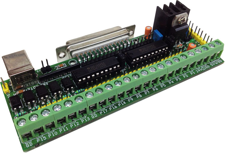
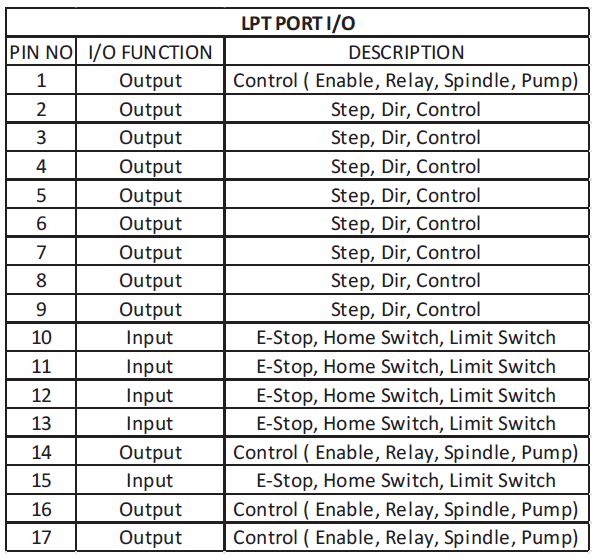
Parallel port I/O break out board designed for Hobby CNC, Routers and Motion controller , This Board is an easy solution to driver stepper Motor driver, AC Servo (with Step-DIR Driver) and DC servo (with Step-DIR Driver), The Board is compatible with various CNC software specially made for LPT port data out. The board has been tested with MACH3 CNC software. All outputs are buffered, all inputs are optical isolated and can be used as emergency switch, limit switch and home switch.
The board has 12 output pins that can control various devices such as stepping motor drivers, AC Servo Driver, DC Servo Driver, Plasma Torch, Pump for coolant, spindle, 5 Input pins are provided for limit or home switches, feedbacks, Emergency switch. All inputs has 470E for current controlled and TTL Voltage input required driving the inputs. This board can be powered with USB input or DC input supply 7V to 36V, keep jumper J2 open in case of USB supply input. Board has Screw Terminals for Inputs and out connections and also provided with 4X6Pin header connecters for outputs. J15 is connected directly to parallel port pins for testing purpose.
Note: For 24V input signal replace of R3, R4, R5, R6, and R7 with 2K2 Ohms.
Features
- Supply 7V to 36V DC
- 25 D SUB Female Connecter for PC LPT Port Interface
- On Board Power LED
- On Board USB Connector for Supply from PC or other USB source
- Jumper Selection for USB Supply Input or External Supply
- All Outputs are buffered
- All inputs are optically isolated
- Two Options for Outputs, Screw Terminals and Header Connectors
- 4X6Pin Header for easy motor driver interface
- On Board L317 Regulator for 5V DC
- Heat sink for regulator
- 5V DC Output for External Circuits
- 3X3 Header Connector for Relay Driver for Spindle, Plasma, Laser, Pump ON/OFF
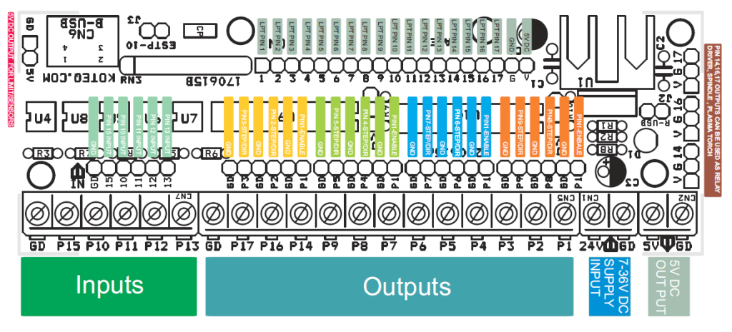
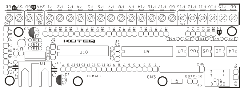
Connections
- CN15 : LPT Port Test Pins
- CN7 : Inputs , Limit Switch, Feedback, Home Switch, Emergency Switch
- CN1 : DC Supply Input 7V to 36V
- CN2 : DC 5V Output
- CN10, CN11, CN12, CN13 : Header Connector for Stepper driver Interface
- CN8, CN9, CN14 : 3X3Pin Header Connector to driver Relay for Outputs
- CN5 : Outputs
- J3 : E Stop Optional Jumper for Test Purpose
- J4, J5 : I/O Direction Control ( Jumper Close to VCC for Normal Operation)
- CN6 : USB Connecter for VCC Supply input ( Keep Jumper J1 Open for USB Supply Input)
- D1: Power LED
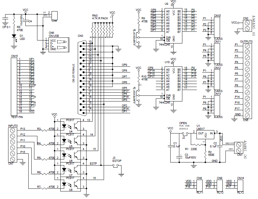
Schematic
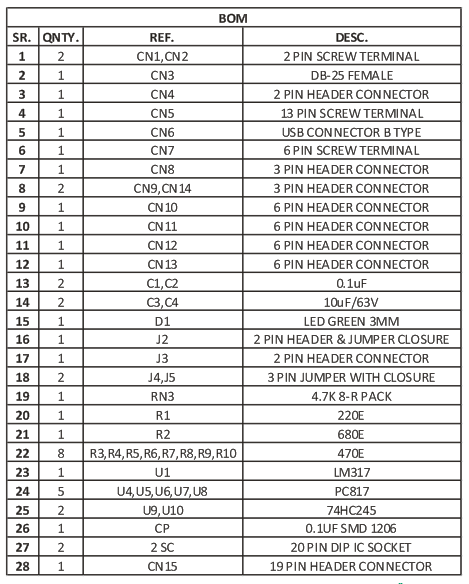
Parts List
Connections
Configuration
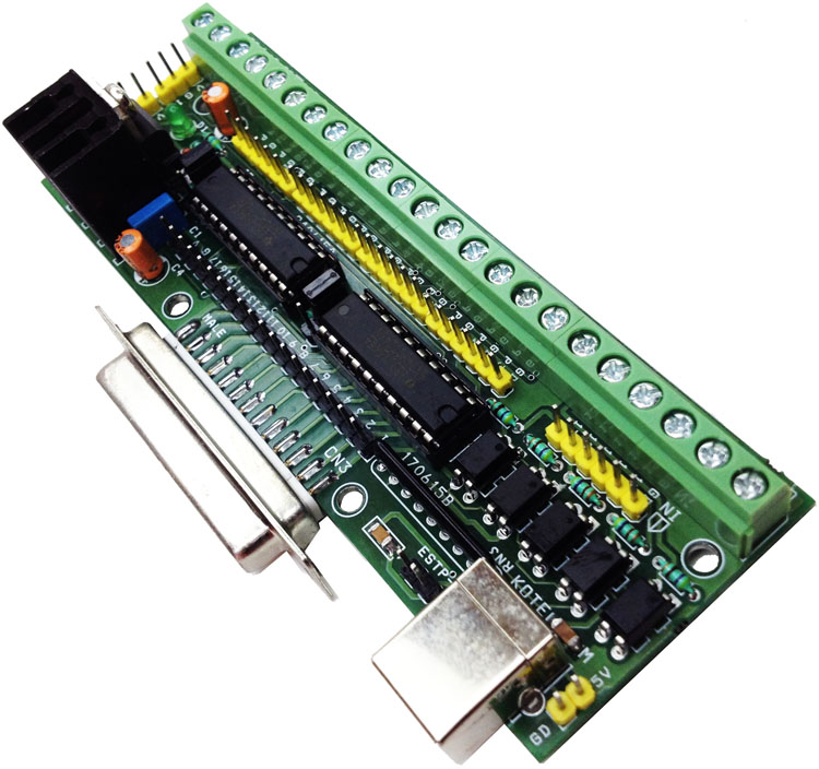
Photos
Please follow and like us:
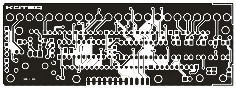
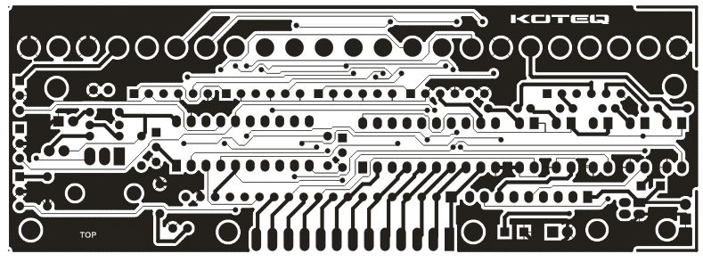
PCB


i want to make a 5 axis breakout board with spindle speed control. but in your design spindle speed control is not available.
please help me on this.
Yes, this is just the breakout board with buffer ICs, you will need additional circuit to control the speed of your motors.
Hello, i have searched for spindle speed control circuit without any luck. Its possible that you help out how we could add that on circuit?
Hi
Thank you for your web site
1- For running stepper motor we need a power supply. Where is input of power supply on board?
2- in the black and white photos there is many black circular that these join with 1 or 2 or 3 or more tin black wire to extensive black area
Is this black wire is error in your design?
I add a link that help you to understand my mind of question 2!
http://s8.picofile.com/file/8333387626/0.png
Thank you again
Hi
Do you have gerber file of this PCB?
Gerber files uploaded above. Thanks
Thanks, So thanks
1- How can I convert gerber to .nc files for CNC millig?
2- Can we run 5-axis CNC by this boards? Do you have controller board for 5-axis CNC?
3- There is a 6-pin set of yellow pins far from the other yellow pins on the board, What is its use?
4- Is this 6 pins yellow for the fifth axis?
I add a link that help you to understand my mind
http://s9.picofile.com/file/8335384376/2.jpg
Thanks again and regards
Asad
And:
6- Can we run this board only by usb port?
Thanks again and regards
Asad
You can run it through USB using a USB to Parallel adapter.
Hi Asad,
please check bellow link, i have used this board for my own large size CNC router, it has 5 axis stepper drives but 2 axis are parallel so actually i have used 4 axis.
http://www.twovolt.com/2018/10/13/my-5-axis-cnc-milling-_-cnc-router-controller_-mach3_mach4_uccnc-machine-control-software/
Please check the video ( Aqcor Inc used this board for 4 axis CNC machine)
https://www.youtube.com/watch?v=ANnz1M8GhNA
https://www.youtube.com/watch?v=jHWk5j1n0q8
Hi Twovolt
Thank you very much for all your reply
I checked all your links and send an email for you
Please check it
Thank you so much again
Hi
Do you have .pcb or .pcbdoc or .ddb or .LYT files of this PCB?
Thanks
I am sorry, only gerber files and PDF document are available for this project.
Hi
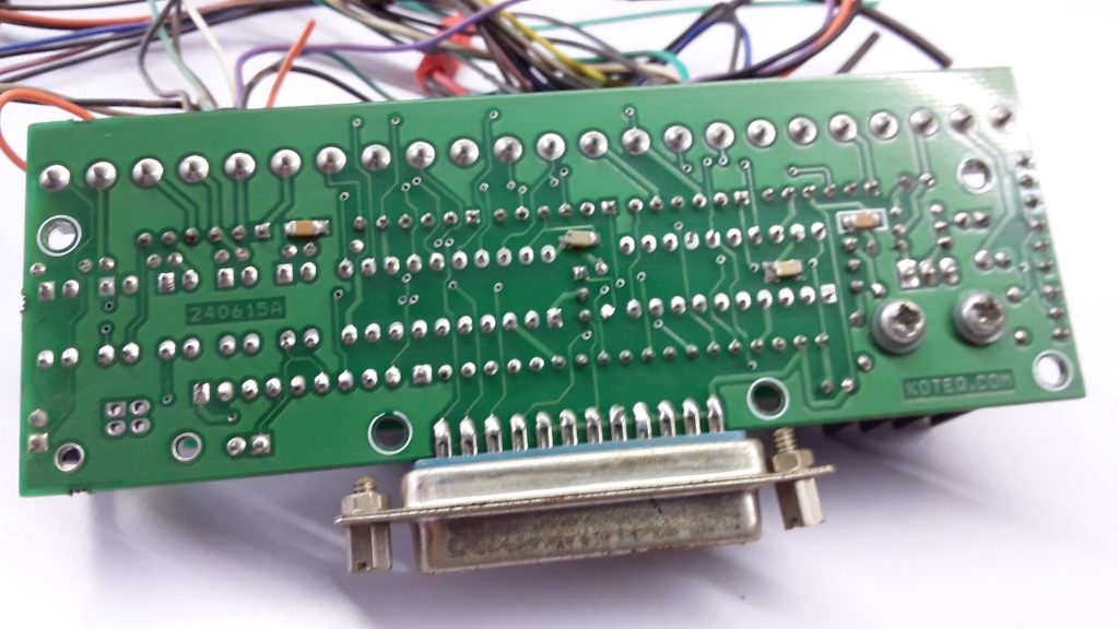
Do you have a photo of behind of board?
Hi
Please share a photo of behind of board
How many smd capacitors are used behind of board?
We will share a photo of the other side of the board in a few days. Thanks!
Okay
I will wait!
Your welcome
I have uploaded a photo of the back of the board in this page.
Hi
we want to run this board by mach3, for configuration of port and pin , What is the phrase in the Port Address that we should write in configuration of port and pin windows and other settings?
Please attention to photo in follow link:
http://s8.picofile.com/file/8343527450/unnamed.png
For connect stepper motor to board, we have 4 Phase connector on stepper motor but on board there is 6 connector that include 3 earth, and that is impossible to connect stepper motor to board we have to have 4 phase connector on board !!!
Please help me to solve problem!
Please help me to solve problem!
The parallel port address is depending on your current PC configuration. One way to check it if to go to Device Manager -> Ports (COM & LPT) -> Right click -> Properties -> Resources -> under Resource settings you should see the resource type Input/Output Range. The first address of the Input/Output Range is the address of LPT Port (common value is 0378)
Regarding stepped motor connections. I will try to draw a graphic to represent the correct connections.
Thank you so much for your reply and answer to my question
Thank you so much for your try to draw the graphic, I need your graph very much, and please sent it early
Hi Asad,
Download Mach 3 manual from Mach website to setup the outputs and inputs, read manual it has answers of all your questions.
It would be great if can email your questions to me at raj@twovolt.com ,
Thanks,
Raj
Dear Raj
I Install mach3 on my system and I assemble this board and I want to run it by mach3 but I need to more data
I’m going headway step by step 🙂 🙂
And may be I have very question and I sent email to you
Hi Asadollah,
One Small yellow mark is 12V SMPS to power the breakout board . blue circle Silver color large size devices is 7.2Amps stepper driver,
This unit has 5 stepper motor driver , 4 provides 4.2Amps and 5th is 7.2 Amps, this 4th one for Z axis, usually Z axis required high current motor to hold vertical spindle load for large size machines.
out of 5 axis , one is spare ( No Use) two are parallel input Y axis has two parallel motors mounted, one is for X axis and 5th for Z-axis.
Regards,
Raj
Hi
I’m Asad that I needed to help for making and install ” PARALLEL PORT BREAKOUT BOARD WITH BUFFER FOR CNC & ROUTERS ” from https://www.electronics-lab.com/project/parallel-port-breakout-board-with-buffer-for-cnc-routers/
I assembled PARALLEL PORT BREAKOUT BOARD and I install mach3 and I don’t change the setting and config of mach3
I install software and I connect an LED to any step/dir pin to GND with 470E resistor to check Pin Enable and Pin Step/Dir on board that we connect them to stepper motor driver, but when I presser direction key on keyboard to turn on X , Y , Z axis pin on board do not turn on LED to check X , Y , Z axis pin
http://s8.picofile.com/file/8346452918/11111111111111111111.jpg
Do I need change the config of mach3?
Thank and regard
Asad
How can I use of this guide?
Best Regards
Hi friend
How are you?
How can I use of this guide?
Can you give me screen shot of all inputs and outputs and other data in configuration windows of mach3?
Best Regards
My friends
No one can answer my request?
How can I config mach3 on this board?
Best regards
Hi dear friend
I assembled this board and I want to config mach3 on my computer to run this boards but I can not
Can any people help me to config mach3 to run this board
Thanks and regards
Hi Asad, configuring Mach3 is a time/resources consuming task and needs a separate article/s to explain it. It can’t be one on comment of this page. This is beyond the scope of this project. I would suggest to take a look around and report your findings so we may able to help on specific questions. The best place to do so it to open a forum topic: https://electronics-lab.com/community/
The Parallel Port Breakout board has very good parameters. However when it comes to CNC Motion controller, I recommend this https://en.cs-lab.eu/shop-cat/cnc-motion-control-system-csmio-products-sets/ . Although it looks like an ordinary small box, connected with a PC and appropriate control software it will supervise the correctness of any CNC appliance operations.
I Mr Mike waht is the speed of this board do you test? also do you have a same board but for lpt2?
great job.
thanks
Alberto Arreda