Automatic ON/OFF Power Switch For Arduino
Over the past few tutorials, we explored several ways to further reduce the power consumption for Arduino based projects so they can last for a long period of time running on the inexpensive AAA batteries. We have tried different approaches like the more recent tutorial on using Atmega328p instead of an Arduino board and as the result of the tutorials showed, we were able to reduce power consumption considerably.
Over the past few tutorials, we explored several ways to further reduce the power consumption for Arduino based projects so they can last for a long period of time running on the inexpensive AAA batteries. We have tried different approaches like the more recent tutorial on using Atmega328p instead of an Arduino board and as the result of the tutorials showed, we were able to reduce power consumption considerably. With all the techniques used to reduce the power, the Arduino still consumed too much current especially the amount of current drawn when the Arduino is in the Idle state. To resolve this, we will need a solution that shuts the Arduino off when the system is idle to preserve battery charge and this is the focus of today’s tutorial.
This project works like most digital watches when you turn them on, it shows you the needed information and after a while goes off to preserve the battery. A typical Arduino consumes about 40mA of current in an idle state while the Atmega328p consumes around 20mA when in the same state. We can conserve this power by using this way to turn on/off the Arduino.
The project basically uses a transistor as a switch to connect the power lines of Arduino to the battery.
Required Components
The following components are required to build this project;
- Arduino Uno
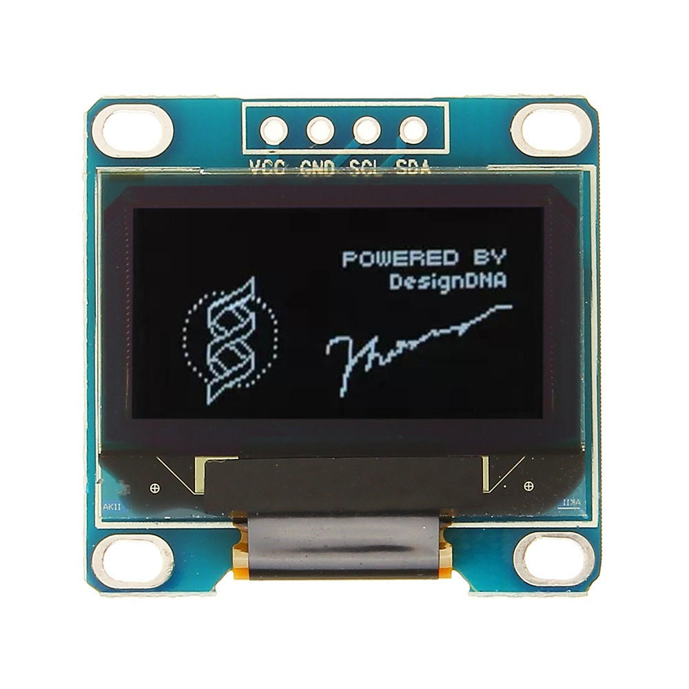
- OLED display
- MOSFET
- Push Buttons
- Small Breadboard
- Multimeter
- Wires
- Battery holder
- Jumper wires
- Resistors
As usual, the exact components used for this tutorial can be bought via the links attached to each of the components above.
Schematics
With all the components acquired, connect them as shown in the schematics below:
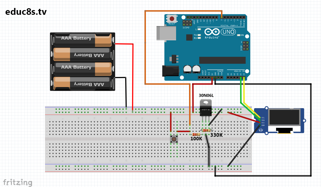
Connecting the components for this project is very easy as there are very few connections to the Arduino. The gate pin of the MOSFET is connected to pin D7 and the OLED display is connected to the I2C pins of the Arduino. A pin map of the connection between the OLED display and the Arduino is shown below;
OLED - Arduino
VCC - 5V
GND - GND
SCL - A5
SDA - A4
The 30N06L MOSFET pinout is shown below and is the control element of this project. When a signal/voltage is applied to the gate (Pin 1 below) of the MOSFET, it allows current to flow between the source (pin 2 below) and the drain (pin 3 below) and when there is no voltage/signal at the gate pin, the current flow between the source and the drain is blocked.
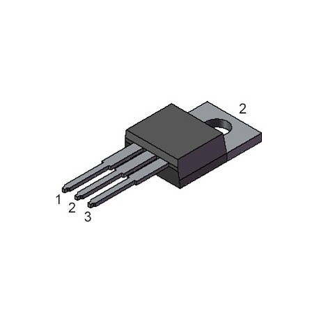
For our application, the MOSFET was connected in such a way that the ground connections from the battery go through to the Arduino. This gives the MOSFET the ability to provide control and turn the Arduino on or off as a complete path of current flow through the Arduino can only be achieved through it. When the button is pressed, the Arduino runs a countdown after which, it drives LOW the Arduino pin D7, which is connected to the gate of the MOSFET. Once this pin goes low, the current flow between the source of the MOSFET and the drain is blocked. With this connection blocked, the ground pin of the Arduino becomes disconnected from the ground pin of the battery and as a result there is no complete path for current to flow and the Arduino goes off. When the button is pressed again, power is supplied once more to the gate of the FET, the Arduino comes on and the process starts all over again.
Code
The code for this project is quite simple as all we do is to display a countdown on the OLED and turn off the Arduino after the countdown. We will use the Adafruit GFX library to easily send data from the Arduino to the OLED Display.
To briefly explain the code, we start by including the libraries needed to use the OLED displays after which we define the pin of the Arduino to which the gate pin of the MOSFET is connected.
//Written By Nick Koumaris
//info@educ8s.tv

#include <Adafruit_SSD1306.h>
#include <Adafruit_GFX.h>

// Pin definitions
#define OLED_RESET 4
const int MOSFETPIN =  7;
Next is the void setup() function. Since the code for this project runs only once everytime the Arduino comes on, I decided to keep all the code within the setup() function and leave the void loop() function empty.
We start by setting the pinMode of the MOSFET pin as output and setting it to HIGH, after which we create an object of the OLED display library.
void setup(void)
{
  pinMode(MOSFETPIN, OUTPUT);
  digitalWrite(MOSFETPIN, HIGH);

  Adafruit_SSD1306 display(OLED_RESET);
Next, we issue the commands to display the “power-off” text on the display and start the countdown process from 5 to 1 after which we turn the MOSFET pin low, using the digital write function.
// text display tests
  display.setTextSize(2);
  display.setTextColor(WHITE);
  display.setCursor(5,0);
  display.println("Power Off");

  display.setTextSize(3);
  display.setTextColor(WHITE);
  display.setCursor(50,30);
  display.print("5");
  display.display();
  delay(1000);

  display.setCursor(50,30);
  display.setTextColor(BLACK);
  display.print("5");
  display.setTextColor(WHITE);
  display.setCursor(50,30);
  display.print("4");
  display.display();
  delay(1000);

  display.setCursor(50,30);
  display.setTextColor(BLACK);
  display.print("4");
  display.setTextColor(WHITE);
  display.setCursor(50,30);
  display.print("3");
  display.display();
  delay(1000);

  display.setCursor(50,30);
  display.setTextColor(BLACK);
  display.print("3");
  display.setTextColor(WHITE);
  display.setCursor(50,30);
  display.print("2");
  display.display();
  delay(1000);

  display.setCursor(50,30);
  display.setTextColor(BLACK);
  display.print("2");
  display.setTextColor(WHITE);
  display.setCursor(50,30);
  display.print("1");
  display.display();
  delay(1000);

  digitalWrite(MOSFETPIN, LOW);
As mentioned earlier, we will leave the void loop() function empty since the code will only be running once everytime the Arduino goes on.
The complete code for the project is attached to the zip file under the download section.
Demo
Copy the code and Upload to your Arduino board, you should see the countdown on the display after which the system goes off. The process can be repeated by pressing the button.
As simple as this project looks, a lot of power is being conserved and this makes the setup ideal for projects that do not require the Arduino staying on while idle. A good example of projects that can be built based on this is a clock system so time is only displayed when the button is pressed.
That’s it for this tutorial guys, feel free to drop any questions you might have as regards this project under the comment section.
The video version of this tutorial is available on youtube.