

PIR Motion Sensor
- Hélio Pereira
- http://www.umodding.info
- consola.repair@gmail.com
- 37.623 Views
- moderate
- Non tested
- 0 Likes

Introduction
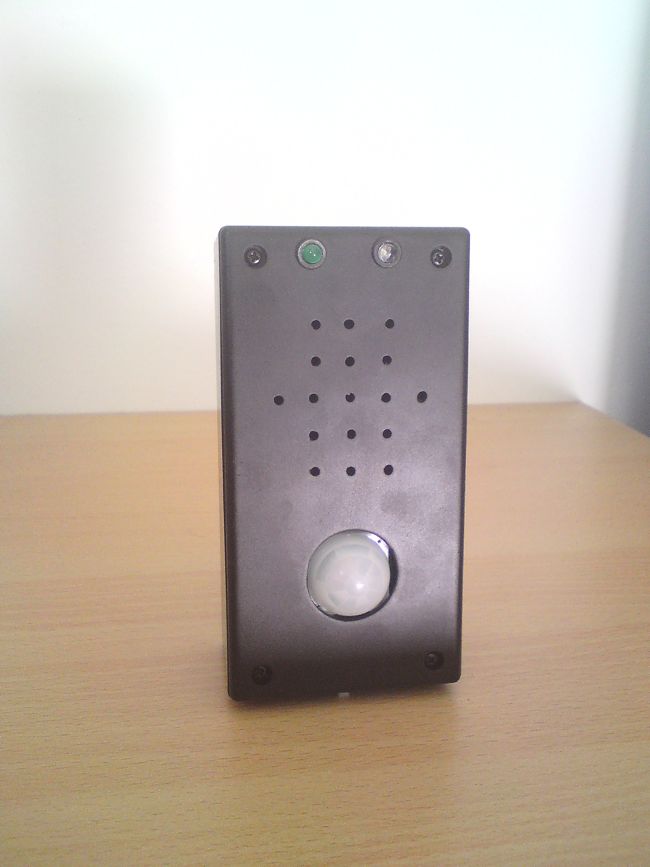
The objective of this project is to use inexpensive PIR sensor to detect if a human has moved. To build this project I use a PIC18F25K20 microcontroller to detect if the sensor had change state and it will emit a sound from the speaker or piezo, the MCU also detect the voltage of the battery in the startup, the algorithm it´s very simple it use an interrupt on change to detect the change on the PIR sensor.
PIR Sensor
PIR sensors allows you to sense motion, almost always used to detect whether a human has moved in or out of the sensors range. They are small, inexpensive, low-power, easy to use and don’t wear out. For that reason they are commonly found in appliances and gadgets used in homes or businesses. PIRs are basically made of a pyroelectric sensor, which can detect levels of infrared radiation. Everything emits some low level radiation, and the hotter something is, the more radiation is emitted. The sensor in a motion detector is actually split in two halves. The reason for that is that we are looking to detect motion (change) not average IR levels. The two halves are wired up so that they cancel each other out. If one half sees more or less IR radiation than the other, the output will swing high or low.
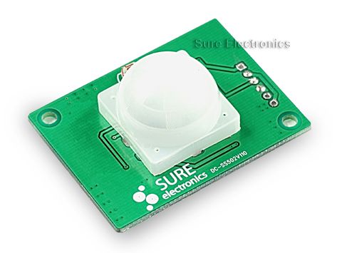
PIR sensor I had use in this project
Schematic
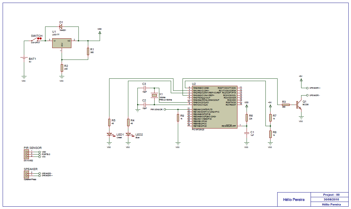
Power Supply
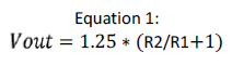
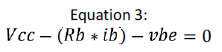
I use a 9V battery and it´s connect to a switch and as a voltage regulator I use an L317T and it will have an output of 3,3V to make that possible I use two resistors R1 and R2 to set the output, i use this equations to calculate R1 and I set R2 to 240 ohms:
POR (Power on reset)
I had to add a RC delay on VPP pin because when I switch on/off the circuit there was a voltage drop because the PIR Sensor and that would generate an unknown state when the MCU was restarted to solve that I add a RC delay, you can use this equations to calculate the delay
![]()
Speaker or Piezo
I use an 8 ohm speaker but you can use a piezo, i use a transistor BC338 (Q1) because the sound wasn´t too loud and should be able to ear that from a different division, with that transistor i get a HFE = 35. You can calculate ic with this equation.
PIR Sensor
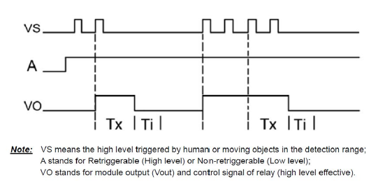
This PIR Sensor works with only 3.3V like the MCU so it´s connect to the output of LM317T it can be connect to a voltage of 8V to 24V, because I use a 9V battery and if the battery gets lower than 8V the PIR sensor wont work that is why I connect the output of LM317T. The Vout of the sensor it is connected to PORTB.0 and when it occurs a change it will cause an interrupt I use a pull down resistor to make sure the PORTB.0 it is in a low state. The sensor takes 10 to 12 seconds to cause another interrupt and the range is between 2m and 3m. There are the graphs of this sensor and the delays.
Algorithm
At startup both LEDs are on and then it will test the battery if is good Led1(Green) will switch on/off three times, if battery it is low Led2(Blue) will switch on/off three times, next it will put the Led1(Green) on, if PORTB.0 doesn´t change state the circuit will remain the same until a change happen and when a change happen it means the sensor detects some movement and a interrupt will occur and Led1 will be turn off and Led2 will be on and a sound will be generate during 5 seconds and then Led2 will switch off and return to the main routine.
Please follow and like us:
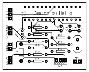
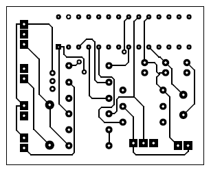
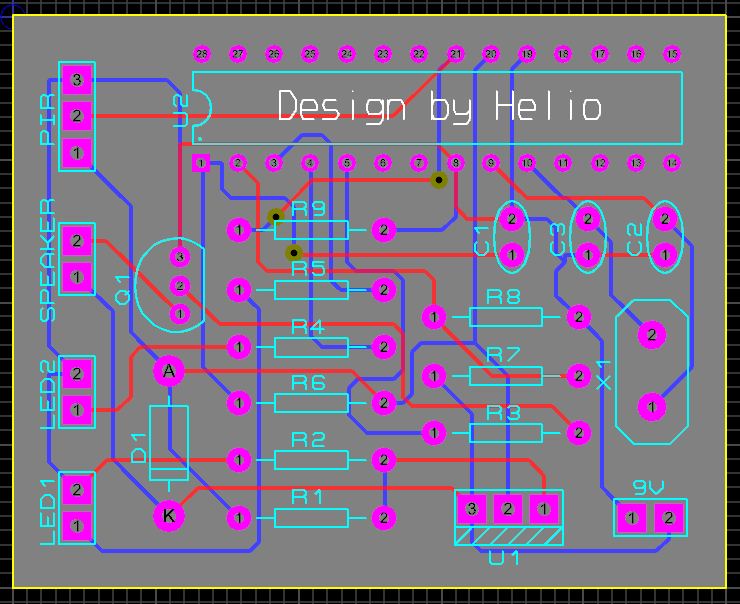
PCB


 – Variable Reluctance Magnetic Pickup to Voltage Converter")

Please sir
PIR Motion sensor .HEX file send
I unable to download
Please give …sir
You can download the .hex from the link above.
sir
can u show a source code?
please sir..
could you email me your source code, I am having trouble configuring the ports for external interrupts used with the sensors. I am using a pic18f4520 but it may be similar enough to your pic to help. Thanks