Amplifier Classes
Introduction Amplifiers are commonly classified depending on the structure of the output stage. Indeed, the power amplification really happens during that stage and therefore the quality and efficiency of the output signal is dictated by the architecture of the amplifier's output.
Introduction
Amplifiers are commonly classified depending on the structure of the output stage. Indeed, the power amplification really happens during that stage and therefore the quality and efficiency of the output signal is dictated by the architecture of the amplifier’s output. The classification consists of an alphabetical arrangement A, B, AB and C that relates to the historical emergence of the amplifiers. During this article, we will give a brief presentation of each amplifier class. Each class denotes the quality of the amplification according mainly to two criteria : the efficiency and the conduction angle.
The efficiency η of an amplifier is defined by the following formula :
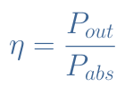
Pout is the power at the output, delivered to a load whereas Pabs is the power absorbed by the amplifier.
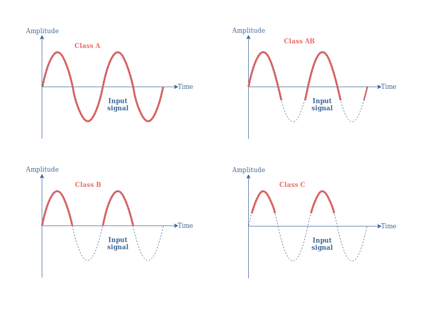
The conducting angle is a measure of how much of the input signal is used to realize the amplification. This value ranges between 360° or 2π rad to 0° or 0 rad. The upper limit 360° means that 100% of the input signal is used for the amplification process while the lower limit 0° means that no signal is taken. We will clarify this further on.
Note on the biasing
There is a reason, before presenting the different classes of amplifiers, that we speak briefly about the biasing. Indeed, if there is truly something to remember about this tutorial is that the class of an amplifier is fully determined by the biasing applied to the transistor.
The diagram presented in Figure 1 should be by now familiar :
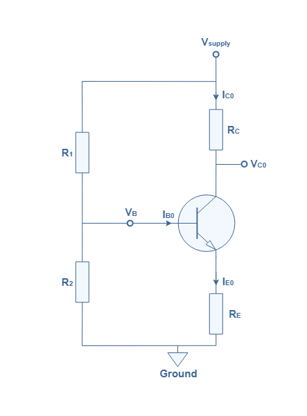
In Figure 1, a BJT transistor of current gain β is biased by a voltage divider network, which consists of two parallel resistances R1 and R2 wired to the base branch. Such as we explain in the tutorial Biasing a BJT, the collector current and voltages when no AC signal is applied (IC0,VC0) sets the operating or quiescent point of the amplifier. The quiescent point is very important because its position in the output characteristic dictates the conducting angle value and therefore the class of the amplifier.
The set of values (IC0,VC0) can be adjusted with the values of the biasing resistances and emitter resistance. Indeed, the collector current IC0 is given by :
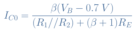
We can clarify two parameters in Equation 2 : 0.7 V corresponds to the voltage VBE, which is the threshold voltage of silicon-based transistors. The resistance R1//R2 is the parallel equivalent resistance of the biasing circuit and is given by the ratio (R1×R2)/(R1+R2).
And the collector voltage VC0 satisfies :

Note that in the following of this tutorial, we will always consider bipolar transistors, but everything we say applies also to other types of transistors such as MOSFETs. Moreover, as a matter of simplification, we use the Common Emitter Amplifier as the configuration under study, the output signals shown in the figures will therefore be inverted.
Class A Amplifier
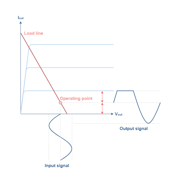
A class A amplifier is characterized by a 360° conduction angle. To achieve this feature, the quiescent point of a Class A amplifier is chosen to be in the middle of the load line such as shown in Figure 2 :
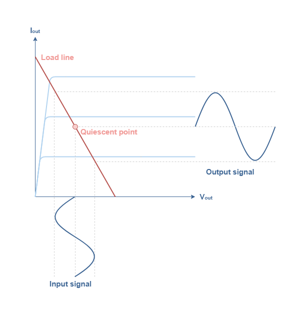
The quiescent point satisfies IC0=Vsupply/2RC and VC0=Vsupply/2. These formulas along with Equation 2 and Equation 3 enable to choose proper values for the biasing resistances to get a class A amplifier.
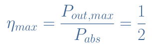
The absorbed power of a class A amplifier is a constant and equal to Pabs=Vsupply×IC0. The output power is the product of the rms output current and voltage : Pout=Vout,rms×Iout,rms. The maximal value of Pout is given when the output current reaches the upper limit IC0 and the output voltage reaches the power supply Vsupply : Pout,max=(Vsupply×IC0)/2. The maximal efficiency is therefore :
In reality, the efficiency is around 20 to 30 % and 50 % can be achieved with a two transistor configuration. This low efficiency highlights the fact that class A amplifiers use power even when no AC input signals are applied.
Class B Amplifier
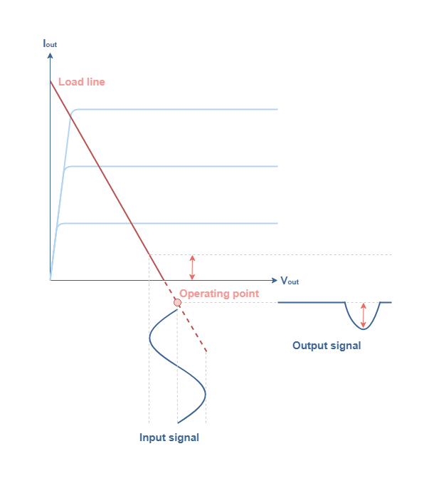
Class B amplifiers have been developed as an answer to the low efficiency of class A amplifiers. This class of amplifier is characterized by a 180° conduction angle, that is to say that they use only half of the input signal to realize the amplification process. To achieve a class B amplification, one needs to bias the circuit accordingly with Figure 3 :
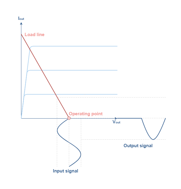
The operating point here is located at the cutoff point and satisfies IC0=0 and VC0=Vsupply.
It is pretty obvious that a faithful amplification can not be achieved with a class B amplifier. To solve this problem, one of the most common solution is to use two transistors (one NPN and one PNP) in a so called “push-pull” configuration :
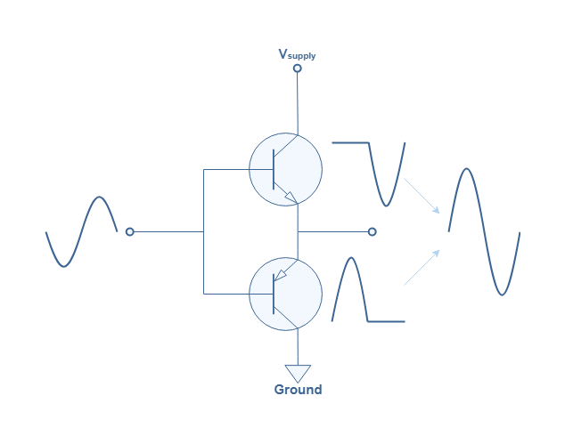
The NPN transistor takes care of amplifying the positive signal of the input and the PNP amplifies the negative signal. The combination results in an addition of the two independent amplifications that reproduce the shape of the input signal.
However, there is a phenomenon called the crossover distortion that prevents class B amplifiers, even in a push-pull configuration to give a 100 % faithful amplification. The cause is due to the threshold voltage of transistors (+0.7 V for NPN and -0.7 V for PNP) that creates an interval of 1.4 V where no amplification at all is performed from neither the NPN nor the PNP transistor. The consequence is a distortion of the signal around the 0 V point of the output signal, well known by audiophiles.
Nonetheless, class B amplifier presents the advantage over the class A to be more efficient with a theoretical maximum efficiency of ηmax=78.5 %. The efficiency observed on real configurations however does not exceed 70 %.
Class AB Amplifier
As the name refers to, class AB amplifier behaves as a combination of class A and class B amplifiers. It has been developed in order to overcome the low efficiency of the class A and the distortion of the class B. Class AB amplifiers are characterized by a conduction angle in the interval ]180°;360°[. The operating point given by the bias circuit is located between a class A quiescent point and the cutoff point :
The operating point of a class AB amplifier satisfies : 0<IC0<Vsupply/2RC and Vsupply/2<VC0<Vsupply.
When the operating point is closer to the cutoff point, the amplifier “becomes” more as a class B than a class A : the signal gets more distorted but the efficiency increases. At the opposite, when the operating point approaches the quiescent point in the middle of the load line, the amplifier behaves more as a class A than a class B : the output is more faithfully reproduced but the efficiency decreases.
Since class AB amplifiers offer a good compromise between the advantages of linearity of class A and the good efficiency of class B, they are commonly used today in many applications. They are usually found in a push-pull configuration, such as presented in Figure 4 and they even eliminate the crossover distortion during the addition of the two amplified outputs from the NPN and PNP transistors.
Class C Amplifier
The last most common class of amplifiers is the class C. It is characterized by a small conduction angle that is in the interval ]0°;90°[. The operating point of class C is beyond the cutoff point, aligned with the load line but in the region of negative biasing currents :
As a matter of fact, the operating point of a class C satisfies : IC0<0 and VC0>Vsupply (which makes sense from Equation 3 if IC0<0).
The high distortion produced by class C amplifiers can be processed by a parallel resonance circuit L//C that consists of an inductance (L) and a capacitance (C). This circuit can indeed convert the output pulses into complete sine waves. For this reason, class C amplifiers are used in high frequency applications.
The biggest advantage of a class C amplifier is its efficiency that is above 78.5 % and can approach 100 % depending how far the operating point is from the cutoff point.
Conclusion
We have seen during this introduction to amplifier classes that for a given configuration (MOSFET, Common Emitter …), the biasing circuit influences heavily the behavior of an amplifier. The way that the amplifiers are biased can be categorized into four main classes :
- Class A : The operating point is in the middle of the load line. It has the highest linearity, but the lowest efficiency around 20-30 %. This class is very much appreciated by audiophiles that consider it to reproduce the purest sound.
- Class B : The operating point matches the cutoff point of the load line. It has a good efficiency of around 70 %, but creates a crossover distortion when used in a push-pull configuration.
- Class AB : The operating point is between the middle and the cutoff point of the load line. It combines both advantages of the class A and B by having a reasonable efficiency above 50 % and a good linearity when used in a push-pull configuration. The class AB is therefore commonly found at the output stage of many applications : audio amplifiers, function generator …
- Class C : The operating point is beyond the cutoff point. It has the highest efficiency above 80 %, but the lowest linearity. Class C amplifiers are restricted to be used for high-frequency applications.
Later, after the development of these technologies, other classes of amplifiers have been developed to answer specific problems, mostly for high-frequency applications. We can mention for example :
- Class D : They are non-linear amplifiers and their efficiency is very high (close to 100%). They are commonly known as PWM amplifiers (Pulse Width Modulation). Class D amplifiers are used in a push-pull configuration and give as an output signal impulsion that can easily be filtrated with inductance and capacitor to reproduce the original desired shape.
- Class E : They are used to amplify RF frequencies from 3 MHz to 10 GHz. Class E amplifiers offer for the upper frequency limit a good efficiency above 70 %.
In the next tutorials, we will give much more detail about each of the most common classes : A, B and AB.


Is this a voltage amplifier? I think this article is very good! I am currently engaged in the electric container industry, so I hope to learn more. What I currently learn is about what industry and products are used in the capacitors, but the meticulous information points are not thorough. So, I will feel amazing when I see some data diagrams or schemes, I will feel amazing