All Activity
- Today
-
 jose vivin joined the community
 -
 arshia_rezaei joined the community
 -

Which wireless protocols are best for home automation?
john28 replied to ilianaboone's topic in Projects Q/A
Pakistan wireless -
Hello Pakistan project
- Yesterday
-
Creating a voice-controlled lighting system can add a touch of magic to any environment. In this blog, we’ll explore how to integrate the DFRobot Gravity: Offline Language Learning Voice Recognition Sensor with a Neo Pixel light strip, all controlled by a Beetle ESP32 C3 microcontroller. Introduction to DFRobot Gravity Voice Recognition Sensor The DFRobot Gravity: Offline Voice Recognition Sensor is a powerful module designed for voice command projects. Here are its key features: Offline Operation: Unlike cloud-based solutions, this sensor works without an internet connection. It’s built around an offline voice recognition chip, making it ideal for applications where internet connectivity is not available or desired. Built-in Command Words: The sensor comes with 121 fixed command words preloaded. These cover a wide range of common instructions, eliminating the need for users to record their voices. Custom Commands: Additionally, the sensor supports the addition of 17 custom command words. This flexibility allows you to train it to recognize specific sounds or phrases, such as whistling, snapping, or even cat meows. Self-Learning Function: The self-learning feature enables you to teach the sensor new commands. For example, you could use it in an automatic pet feeder. When your cat emits a meow, the sensor recognizes it and triggers the feeder to provide food promptly. User-Friendly Design: With its straightforward interface, the sensor simplifies voice interaction projects. Whether you’re building smart home appliances, toys, lighting fixtures, or robotics, this sensor provides a flexible solution. Key Features: Offline Operation: Works without the need for an internet connection. Custom Commands: Supports adding custom voice commands. Compatibility: Can be used with Arduino, Raspberry Pi, Python, and Beetle ESP32 C3. Get PCBs for Your Projects Manufactured You must check out PCBWAY for ordering PCBs online for cheap! You get 10 good-quality PCBs manufactured and shipped to your doorstep for cheap. You will also get a discount on shipping on your first order. Upload your Gerber files onto PCBWAY to get them manufactured with good quality and quick turnaround time. PCBWay now could provide a complete product solution, from design to enclosure production. Check out their online Gerber viewer function. With reward points, you can get free stuff from their gift shop. Also, check out this useful blog on PCBWay Plugin for KiCad from here. Using this plugin, you can directly order PCBs in just one click after completing your design in KiCad. Neo Pixel: A Symphony of Lights Neo Pixel LEDs are individually addressable RGB LEDs, which means each LED’s color and brightness can be controlled independently. This makes them ideal for creating dynamic and colorful lighting effects. Why Choose Neo Pixel? Individual Addressability: Control each LED separately. Vibrant Colors: Create a spectrum of colors with RGB LEDs. Energy Efficient: Low power consumption with bright output. The Beetle ESP32 C3 Controller: The Brain Behind the Operation The Beetle ESP32 C3 is a small, powerful development board ideal for IoT projects. It features: A RISC-V 32-bit single-core processor for efficient performance. A coin-sized design, making it highly portable. Up to 13 digital I/O ports for various connections. Onboard battery management for direct li-ion battery connection. Wi-Fi and Bluetooth 5 (LE) support for versatile networking. Compatibility with Arduino IDE, ESP-IDF, and MicroPython, and supports C and Python programming. An expansion board for additional power sources and a GDI for screens. Operates at 3.3V with a Type-C input of 5V DC and a charging current of 400mA. Suitable for a wide range of temperatures, from -40 to 105°C. It’s a compact yet feature-rich board that’s adaptable for a variety of applications. Advantages of Beetle ESP32 C3: Connectivity: Wi-Fi and Bluetooth ready. Powerful: Enough processing power to handle complex tasks. Versatile: Compatible with various programming environments. Bringing It All Together To create a voice-controlled Neo Pixel light system, we’ll need to connect the DFRobot Gravity sensor to the Beetle ESP32 C3 and then to the Neo Pixel strip. The Beetle ESP32 C3 will listen to voice commands through the sensor and control the Neo Pixel lights accordingly. Adding Custom Commands in DFRobot Gravity Voice Recognition Sensor Let’s dive into the process of adding custom command words: First, let's upload the following sketch to the Beetle board, this sketch will show you the exact command ID which is related to the custom voice instructions. /*! * @file i2c.ino * @brief Control the voice recognition module via I2C * @n Get the recognized command ID and play the corresponding reply audio according to the ID; * @n Get and set the wake-up state duration, set mute mode, set volume, and enter the wake-up state * @copyright Copyright (c) 2010 DFRobot Co.Ltd (http://www.dfrobot.com) * @licence The MIT License (MIT) * @author [qsjhyy]([email protected]) * @version V1.0 * @date 2022-12-30 * @url https://github.com/DFRobot/DFRobot_DF2301Q */ #include "DFRobot_DF2301Q.h" //I2C communication DFRobot_DF2301Q_I2C DF2301Q; void setup() { Serial.begin(115200); // Init the sensor while( !( DF2301Q.begin() ) ) { Serial.println("Communication with device failed, please check connection"); delay(3000); } Serial.println("Begin ok!"); /** * @brief Set voice volume * @param voc - Volume value(1~7) */ DF2301Q.setVolume(4); /** * @brief Set mute mode * @param mode - Mute mode; set value 1: mute, 0: unmute */ DF2301Q.setMuteMode(0); /** * @brief Set wake-up duration * @param wakeTime - Wake-up duration (0-255) */ DF2301Q.setWakeTime(15); /** * @brief Get wake-up duration * @return The currently-set wake-up period */ uint8_t wakeTime = 0; wakeTime = DF2301Q.getWakeTime(); Serial.print("wakeTime = "); Serial.println(wakeTime); /** * @brief Play the corresponding reply audio according to the command word ID * @param CMDID - Command word ID * @note Can enter wake-up state through ID-1 in I2C mode */ // DF2301Q.playByCMDID(1); // Wake-up command DF2301Q.playByCMDID(23); // Common word ID } void loop() { /** * @brief Get the ID corresponding to the command word * @return Return the obtained command word ID, returning 0 means no valid ID is obtained */ uint8_t CMDID = 0; CMDID = DF2301Q.getCMDID(); if(0 != CMDID) { Serial.print("CMDID = "); Serial.println(CMDID); } delay(3000); } Now let's talk to our sensor and add custom voice commands. First, we need to use this "Learning command word" command to add a new command. Here I have added 4 different commands. These are the commands and their related command IDs. Lights on = 5 Lights off = 6 Lights to red = 8 Lights to green = 7 Integrate Neo Pixels with Voice Sensor Here’s a simple example that tests our neo pixel led: // NeoPixel Ring simple sketch (c) 2013 Shae Erisson // Released under the GPLv3 license to match the rest of the // Adafruit NeoPixel library #include <Adafruit_NeoPixel.h> #ifdef __AVR__ #include <avr/power.h> // Required for 16 MHz Adafruit Trinket #endif // Which pin on the Arduino is connected to the NeoPixels? #define PIN 0 // On Trinket or Gemma, suggest changing this to 1 // How many NeoPixels are attached to the Arduino? #define NUMPIXELS 8 // Popular NeoPixel ring size // When setting up the NeoPixel library, we tell it how many pixels, // and which pin to use to send signals. Note that for older NeoPixel // strips you might need to change the third parameter -- see the // strandtest example for more information on possible values. Adafruit_NeoPixel pixels(NUMPIXELS, PIN, NEO_GRB + NEO_KHZ800); #define DELAYVAL 500 // Time (in milliseconds) to pause between pixels void setup() { // These lines are specifically to support the Adafruit Trinket 5V 16 MHz. // Any other board, you can remove this part (but no harm leaving it): #if defined(__AVR_ATtiny85__) && (F_CPU == 16000000) clock_prescale_set(clock_div_1); #endif // END of Trinket-specific code. pixels.begin(); // INITIALIZE NeoPixel strip object (REQUIRED) } void loop() { pixels.clear(); // Set all pixel colors to 'off' // The first NeoPixel in a strand is #0, second is 1, all the way up // to the count of pixels minus one. for(int i=0; i<NUMPIXELS; i++) { // For each pixel... // pixels.Color() takes RGB values, from 0,0,0 up to 255,255,255 // Here we're using a moderately bright green color: pixels.setPixelColor(i, pixels.Color(0, 150, 0)); pixels.show(); // Send the updated pixel colors to the hardware. delay(DELAYVAL); // Pause before next pass through loop } } Here is the neo-pixel response. Finally, let's integrate the voice sensor with our neo-pixel. #include "DFRobot_DF2301Q.h" #include <Adafruit_NeoPixel.h> #define PIN 0 // Neo Adafruit_NeoPixel strip = Adafruit_NeoPixel(8, PIN, NEO_GRB + NEO_KHZ800); //I2C communication DFRobot_DF2301Q_I2C DF2301Q; void setup() { Serial.begin(115200); strip.begin(); strip.setBrightness(100); strip.show(); while ( !( DF2301Q.begin() ) ) { Serial.println("Communication with device failed, please check connection"); delay(3000); } Serial.println("Begin ok!"); DF2301Q.setVolume(7); DF2301Q.setMuteMode(0); DF2301Q.setWakeTime(15); uint8_t wakeTime = 0; wakeTime = DF2301Q.getWakeTime(); Serial.print("wakeTime = "); Serial.println(wakeTime); DF2301Q.playByCMDID(23); // Common word ID } void loop() { uint8_t CMDID = 0; CMDID = DF2301Q.getCMDID(); if (0 != CMDID) { Serial.print("CMDID = "); Serial.println(CMDID); } if (CMDID == 5) { strip.clear(); // Set all pixel colors to 'off' for (int i = 0; i < 12; i++) { // For each pixel... strip.setPixelColor(i, strip.Color(255, 255, 255)); strip.show(); } } else if (CMDID == 6) { strip.clear(); for (int i = 0; i < 12; i++) { // For each pixel... strip.setPixelColor(i, strip.Color(0, 0, 0)); strip.show(); } } else if (CMDID == 7) { strip.clear(); for (int i = 0; i < 12; i++) { // For each pixel... strip.setPixelColor(i, strip.Color(255, 0, 0)); strip.show(); } } else if (CMDID == 8) { strip.clear(); for (int i = 0; i < 12; i++) { // For each pixel... strip.setPixelColor(i, strip.Color(0, 255, 0)); strip.show(); } } } This script sets up the Beetle ESP32 C3 to control a Neo Pixel strip and changes the color based on voice commands received from the DFRobot Gravity sensor. Conclusion Integrating the DFRobot Gravity Voice Recognition Sensor with Neo Pixel lights controlled by a Beetle ESP32 C3 offers endless possibilities for creating interactive and responsive environments. Whether it’s for home automation, art installations, or educational purposes, this combination of technology brings both functionality and creativity to your projects. I hope this blog post inspires you to create your voice-controlled lighting system. If you have any questions or need further guidance, feel free to reach out!
-
 Mobile LIdar Viewer joined the community
 -
 Workers Compensation Insurance Trucking joined the community
 - Last week
-
Hey, when you're in college, essay writing services like https://www.killerpapers.org/unemployed-professors-review-is-it-legit can be a total game-changer. Picture this: you've got a crazy workload or a super tight deadline, and bam! These services swoop in to save the day. They're like your secret weapon for acing assignments without the stress. Plus, they help you level up your game by providing top-notch content that impresses your professors. It's like having a personal tutor who's got your back whenever you need it. So yeah, essay writing services? Definitely worth checking out during your college journey!
-
 Khôi Nguyễn Phi Anh joined the community
 -
 mUSTANG1969 changed their profile photo
 -
 Armela Kaye joined the community
 -
 Antony Chàvez joined the community
 -
ElectronicSpices.com is india's largest Electronic component online store for selling electronic items at best price. We offer products from a wide range of categories, like resistors, capacitors, inductors, switches, and sockets. Sensors etc. Placing an order with us is simple and hassle-free.
-
.thumb.jpg.7b644e286636fd42fb773451f6dd3ec6.jpg) Electronic Spices joined the community
Electronic Spices joined the community -
 majid16521 joined the community
 -
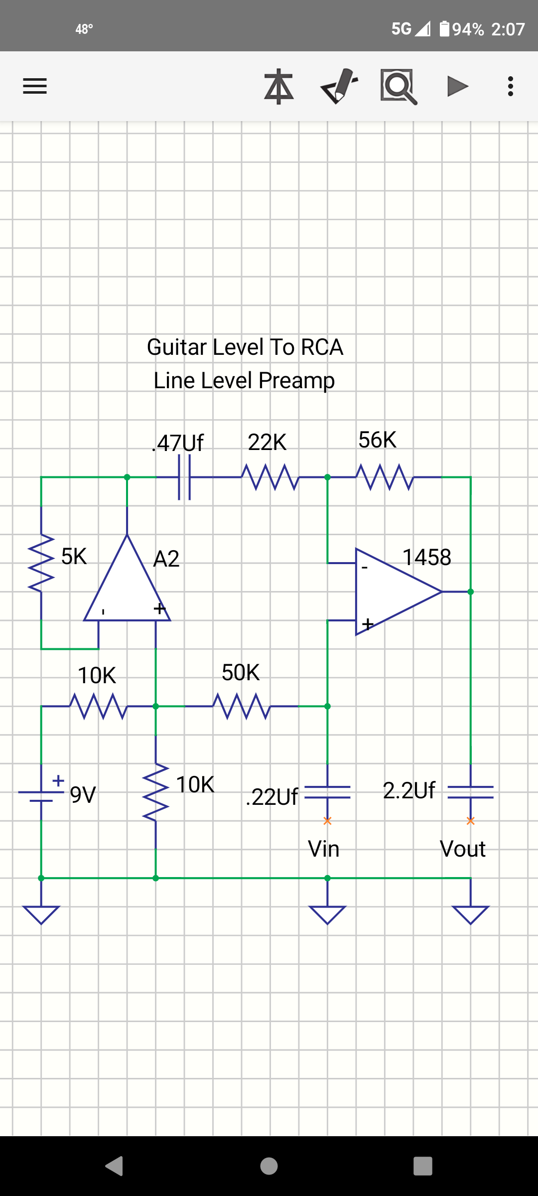
 WANTED: Chicago transformer with a base mount and side terminals in working condition. 3500v test. Primary: 120 volts 50/60 Hz Secondary: 960 volts @ 313mA Apparent Power: 300 VA Dimensions: 6" x 6-1/2" x 7-1/4"H URGENT Please get in contact! We are ready to pay a $75 fee for finding this product (in stock) and its distributor.
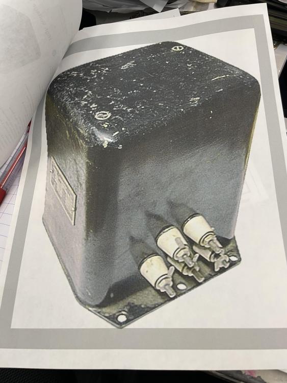
-
Hello How to make buzzer
-

Which wireless protocols are best for home automation?
bidrohini replied to ilianaboone's topic in Projects Q/A
Coverage: Zigbee: Zigbee operates on a mesh network, allowing devices to relay signals to extend coverage throughout your home. It's particularly effective for larger homes with multiple floors and rooms. Z-Wave: Similar to Zigbee, Z-Wave also utilizes a mesh network for extended coverage. Both Zigbee and Z-Wave are suitable for multi-room and multi-floor setups. Wi-Fi: Wi-Fi offers excellent coverage but may experience interference in densely populated areas or larger homes with thick walls. Bluetooth: Bluetooth's coverage is typically limited to a single room, making it less ideal for expansive smart home setups. Energy Consumption: Zigbee: Zigbee devices are known for their low power consumption, leading to longer battery life for battery-operated devices. Z-Wave: Z-Wave devices also boast low power consumption, contributing to extended battery life. Wi-Fi: Wi-Fi devices tend to consume more power compared to Zigbee and Z-Wave, potentially leading to more frequent battery replacements. Bluetooth: Bluetooth Low Energy (BLE) is designed for energy efficiency, but battery life can still vary depending on device usage. Some smart home hubs support multiple wireless protocols, allowing you to integrate devices using different standards. This provides flexibility and compatibility but may require additional setup and configuration.The best wireless protocol for your smart home depends on your specific requirements, including coverage, energy efficiency, security, and future expansion plans. Consider factors such as the size of your home, the types of devices you plan to connect. Here is an example of a wifi-based home automation project. https://www.pcbway.com/project/shareproject/Alexa_Control_Smart_Home_Automation_Using_Arduino_Nano_ESP32_45d0b79a.html -
 Lithium battery packs have revolutionized the way we power our devices, offering higher energy density, longer lifespan, and faster charging capabilities compared to traditional batteries. Understanding the intricacies of lithium batteries is crucial for maximizing their benefits while ensuring safety. In this comprehensive guide, we delve into the world of lithium battery packs, covering everything from their chemistry to disposal. Chemistry of Lithium Batteries Lithium batteries operate based on the movement of lithium ions between the positive and negative electrodes. This unique chemistry allows for high energy density and efficient energy storage. Types of Lithium Batteries There are several types of lithium batteries, including lithium-ion (Li-ion), lithium-polymer (LiPo), and lithium iron phosphate (LiFePO4). Each type has its own advantages and is tailored for specific applications. Advantages over Other Batteries Lithium batteries outperform traditional lead-acid and nickel-based batteries in several aspects, including higher energy density, lower self-discharge rate, and longer lifespan. They are also more lightweight, making them ideal for portable devices. Safety Considerations Overcharging Risks Overcharging lithium batteries can lead to thermal runaway, a potentially dangerous situation where the battery overheats and catches fire or explodes. Implementing proper charging protocols and using quality chargers is essential for preventing overcharging incidents. Thermal Runaway Thermal runaway occurs when the internal temperature of a lithium battery rises uncontrollably, leading to rapid degradation or catastrophic failure. Thermal management systems and temperature monitoring can help mitigate this risk. Safe Handling Practices To minimize the risk of accidents, it's crucial to handle lithium batteries with care. Avoid exposing them to extreme temperatures, puncturing or crushing them, and using damaged batteries. Follow manufacturer guidelines for safe usage and storage. Common Applications Consumer Electronics Lithium battery packs power a wide range of consumer electronics, including smartphones, laptops, cameras, and wearable devices. Their compact size and high energy density make them ideal for portable gadgets. Electric Vehicles The automotive industry has embraced lithium battery technology for electric vehicles (EVs) due to its superior energy efficiency and environmental benefits. Lithium batteries enable longer driving ranges and faster charging times, driving the transition towards sustainable transportation. Renewable Energy Storage Lithium battery packs play a crucial role in storing energy generated from renewable sources such as solar and wind power. They provide a reliable and efficient solution for grid stabilization and off-grid energy storage applications. Factors Affecting Performance Temperature Extreme temperatures can significantly impact the performance and lifespan of lithium batteries. Operating them within recommended temperature ranges and implementing thermal management systems is essential for optimal performance. Charge and Discharge Rates Lithium batteries perform best when charged and discharged at moderate rates. Rapid charging or discharging can degrade battery health and lead to reduced capacity over time. Cycle Life The number of charge-discharge cycles a Lithium-Ion Battery can undergo before reaching the end of its usable life varies depending on factors such as depth of discharge, operating conditions, and battery chemistry. Proper maintenance and usage practices can extend the battery's cycle life. Maintenance and Care Storage Guidelines When storing lithium batteries for an extended period, it's essential to store them at partial charge in a cool, dry place. Avoid fully charging or discharging the batteries before storage to prevent capacity loss and degradation. Usage Tips To maximize the lifespan of lithium batteries, avoid deep discharges and extreme temperatures during usage. Implementing regular maintenance routines, such as firmware updates for electronic devices, can also help optimize battery performance. Disposal and Recycling Environmental Impact Improper disposal of lithium batteries can have significant environmental consequences, as they contain toxic chemicals that can leach into the soil and water. Recycling lithium batteries helps minimize environmental pollution and conserves valuable resources. Recycling Processes Lithium battery recycling involves separating battery components, such as lithium, cobalt, and nickel, for reuse in new battery production or other industries. Advanced recycling technologies are continuously being developed to improve efficiency and minimize waste. Conclusion Lithium battery packs offer a compelling combination of high energy density, long lifespan, and fast charging capabilities, making them the preferred choice for powering modern devices and vehicles. By understanding the chemistry, safety considerations, and best practices for usage and disposal, consumers can harness the full potential of lithium batteries while minimizing risks to the environment and personal safety.
 -
DEFAMATION VICTIM: STEPHANIE BEAUDEAU EMSWORTH. A criminal cyberattacker and stalker, with significant mental health problems, has obsessively posted on this site and many other internet sites, vicious SLANDER about 4 members of the same family, including a very young child.
- Earlier
-
Ultrasonic Sensor with Home Assistant
bidrohini replied to CETECH's topic in Electronic Projects Design/Ideas
The project looks really great. Here is another good ESPhome project https://www.pcbway.com/project/shareproject/homeThing_S3_2b3ac3ac.html HomeThing is a universal remote platform that works with any smart home. Now faster, with Voice Assistant, and easier to set up. -
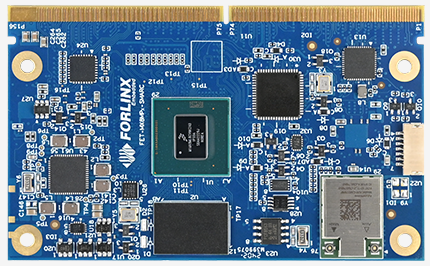
 Problems Description: When using the Forlinx RK3588 SoM and a homemade carrier board, the system enters MaskRom mode as soon as it's powered on. The difference between the Forlinx carrier board and the homemade carrier board lies in the value of the ground capacitors in Figure 1, where one is 10uF and the other is 100nF. Solutions: The MaskRom mode of OK3588-C can only be pulled low to GND by the BOOT _ SARADC _ IN0 when the CPU starts to detect. The OK3588-C development board enters MaskRom mode by tapping the BOOT _ SARADC _ IN0 to GND. As shown in the figure 1: This part of the circuit has a 100 nF capacitor C3 to ground. If this capacitor is replaced with a larger one, such as a 10 uF capacitor, it will cause the development board to enter MaskRom mode as soon as it is powered on. Figure 1 This is because capacitors have the property of blocking direct current while allowing alternating current to pass, and they also exhibit charging and discharging characteristics. When the power is turned on, the capacitor charges instantaneously, and the voltage across the capacitor cannot change abruptly. Initially, the voltage across the capacitor is zero while it charges, and then it rises exponentially according to a certain pattern until it reaches a steady state. Entering a steady state is equivalent to an open circuit. The charging process is shown in Figure 2. Figure 2 The charging and discharging time of a capacitor increases as its capacitance value increases. A 10uF capacitor has a longer charging time, and it enters a steady state slowly. When the OK3588-C SoM starts up, if the CPU detects that the signal level of the BOOT_SARADC_IN0 pin is within the low voltage range, it assumes that this pin is pulled to GND, thus entering MaskRom mode. The solution is to remove the 10uF capacitor or replace it with a 100nF capacitor.
 -
Greetings! I hope everyone is doing well. I am looking for the name of this electronic component if someone knew please reply and tell. It is located on the cold side part of the PCB inside my E-bike charger. Thank you in advanced!
-
Pressure displacement analyzer is a professional instrument used to measure the deformation of materials under force. It can measure the pressure, strain, displacement and other mechanical parameters of the material, and analyze and process the parameters through the built-in software system and algorithm, so as to obtain the mechanical properties of the material. Pressure and displacement analyzer is widely used in material science, machinery manufacturing, construction engineering, aerospace and other fields. With the continuous progress of science and technology and the rapid development of industrial manufacturing, the requirements for the mechanical properties of materials in industrial production are also rising, so more accurate and reliable measuring instruments are needed to meet the demand. The emergence of stress-strain displacement analyzers fills the gap in material mechanics performance testing equipment, greatly enhancing the accuracy and efficiency of material testing. The characteristics of stress-strain displacement analyzers to be considered during use include: High-precision measurement: It can measure the displacement change of the object under the action of pressure with high precision to ensure the accuracy and reliability of the measurement results; High reliability: It can measure stably for a long time under extreme conditions, and is suitable for various complex environments and application scenarios; The operation is simple, and the complex measurement task can be realized through simple operation, so that the work efficiency is improved; Multi-functional: It can perform various functions such as automatic recording, data processing, result analysis, and report generation to meet the needs of different application scenarios; Intuitive display: Pressure displacement analyzers usually have LCD displays, which can intuitively display measurement results and parameters, making it easy for users to carry out real-time monitoring and data analysis; Convenient data processing: Measurement data can be stored in the internal memory or external devices, and support a variety of data format export, convenient for users to carry out later data processing and analysis. Forlinx Embedded recommends using FETMX8MM-C as the product implementation solution. In this solution, the main functions of the i.MX8MM-C SoM are: The human-machine interaction module displays real-time data transmitted from the MCU via MIPI, and performs drawing and data display; Data processing and storage is achieved through USB interface conversion to ULPI LINK for communication with the MCU end. Data is received and stored in TF cards or USB drives, then processed to output in a more concise and understandable form; Network transmission and remote control are facilitated through a Gigabit Ethernet port, allowing for remote monitoring of screens, network backups, and system parameter restoration. Advantages: Equipped with an ARM Cortex-A53 quad-core CPU running at 1.8GHz and paired with 2GB of DDR4 RAM, it offers high performance and computational power, providing a significant advantage in data processing; The compact size of only 56mm * 36mm meets the requirements of miniaturization and portability of equipment and reduces the size of products; Support 4-line mipi display, maximum 1.5g bps transmission, high-definition output image; Long supply cycle, join NXP product long-term supply plan, guarantee at least 10 years of supply period; The operating environment temperature ranges from -40°C to 85°C, meeting the requirements for industrial and general industrial applications. The above is the pressure displacement curve analysis solution provided by Forlinx Embedded based on the FETMX8MM-C SoM. We hope it can assist you in your selection process.
-
 Guy marcel kalambay changed their profile photo
 -
 Tiago Alves changed their profile photo
 -
 JorgeMiller reacted to a post in a topic:
Ultrasonic Sensor with Home Assistant
JorgeMiller reacted to a post in a topic:
Ultrasonic Sensor with Home Assistant
-
Looking for an Assistant: Which wireless protocols are best for home automation? Hello, everyone! I am planning to upgrade my home to a smart home system, involving lighting, security, temperature control and other aspects. But there is some confusion when it comes to choosing the right wireless protocol, because there are so many choices on the market, and each seems to have its own advantages and limitations. Mainly considering Zigbee, Z-Wave, Wi-Fi and Bluetooth protocols as they seem to be the most popular on the market. Here are a few questions, hoping to get some advice from everyone: For a home system covering multiple rooms and floors, which wireless protocol is better at providing stable and wide coverage? Which protocol is more efficient when it comes to energy consumption management? Because I want to reduce the frequency of battery replacement as much as possible. Which protocol will be more secure in terms of compatibility and future expansion? If you have experience using multiple protocol integration solutions, can you share the pros and cons? If you have relevant experience or know some industry insights, please share your knowledge and advice. I'm really looking forward to getting some practical solutions out of this community. Thank you all so much for your time and help!
-
HMI (Human-Machine Interface) is a medium for interaction and information exchange between systems and users. It is essential in fields involving human-machine communication and can be seen in many industries. As technology advances, HMI continues to evolve. In addition to data collection, control, and display, future HMI will incorporate new interactive forms to enable machines to operate more intelligently and interact more efficiently with humans. The increasing demand for more intelligent human-machine interactions also raises higher requirements for processors used in HMI applications. To assist engineers with terminal development requirements in selecting the main controller, in this article, the author will provide a detailed explanation of the three key elements that will influence the next generation of HMI. Smarter Interaction AI support will help the new generation of HMI achieve more powerful functions. For example, AI face recognition can be used to realize human access to devices, and AI gesture recognition can also be used to realize contactless control between people and devices. At the same time, it also allows the equipment to monitor and analyze the current system status more accurately. For example, in the medical field, intelligent HMI systems can allow doctors to interact with medical devices through gestures. Balance of Power Consumption And Performance AI function support puts forward higher requirements for the performance of processors, and the high integration and performance improvement of chips will inevitably increase power consumption and generate more heat. For devices with limited size to be able to adapt to a more diverse and complex environment, it is very important to have multiple power consumption mode options - the freedom to choose between high power consumption, low power consumption, and ultra-low power consumption modes. This not only allows performance to be properly optimized, but also helps to better control costs, achieving a balance between power consumption and performance. Enhanced Communication Capabilities The increase in real-time industrial communication protocols has also brought new challenges to the new generation of HMI applications. For example, the HMI applied in the smart factory not only needs to carry the task of exchanging information between people and equipment, but also needs to complete the function of communicating with other machines and equipments, which means that the HMI needs to have a stronger connection and control function. FET6254-C SoM launched by Forlinx Embedded not only meets the traditional HMI's human-computer interaction needs but also can realize the three key elements mentioned above, empowering the new generation of HMI. FET6254-C System on module is built on the TI Sitara™ AM6254 industrial-grade processor, featuring a quad-core Arm Cortex-A53 architecture with a maximum frequency of up to 1.4GHz. It enables edge AI capabilities, making the HMI smarter and more intelligent. During the development process, rigorous environmental temperature testing, pressure testing, and long-term stability testing were conducted to ensure that it can operate stably in harsh environments. Not only the performance is guaranteed, but also the power consumption can be very low. Through a simplified power architecture design, the AM62x processor exhibits extremely low power consumption performance, with power as low as 5mW in deep sleep mode. With a core voltage of 0.75V, the operating power can be kept below 1.5W, greatly reducing system power consumption. AM62x processor, as the next-generation MPU product in the TI Sitara™ product line, offers richer resource interfaces compared to the previous generation classic processor, the AM335x. It includes features such as 2 x Gigabit Ethernet with TSN support, 3 x CAN-FD, 9 x UART, 2 x USB 2.0, 2 x LVDS interfaces, RGB, camera, audio, and more. This enhances the product's scalability and flexibility for various applications. In addition to the advantages mentioned above, Forlinx Embedded has also ported a Chinese input method for the Linux system on the FET6254-C SoM. This makes it more convenient to invoke applications and helps users simplify their development workload. Moreover, the FET6254-C embedded board supports system burning via USB flash drive or TF card and can replace Uboot, Kernel, and device tree in the operating system, making it easy to achieve remote updates for products and helping users save on-site maintenance costs. The combination of stable quality and rich functionality allows Forlinx Embedded's FET6254-C core board to demonstrate unique advantages in next-generation HMI applications, empowering HMI across industries such as industrial control, power, transportation, and healthcare. This enables machines to operate more intelligently and interact more efficiently with humans. The above is the HMI solution recommendation based on the Forlinx Embedded FET6254-C SoM. We hope it can be helpful for your product design.
-
 Sahlan Soiban changed their profile photo
 -
1. Compile the fw_printenv tool Execute under the uboot source path, and then generate the executable file of the fw _ printenv under tools/env. . /opt/fsl-imx-x11/4.1.15-2.0.0/environment-setup-cortexa7hf-neon-poky-linux-gnueabimake env 2. Configure fw_env.config file Modify the fw_env.config file under tools/env in the uboot source directory according to the mtd partition, the location and size of the UBOOT environment variables, etc. See the instructions in the fw_env.config file and the /tools/env/README file for specific modifications. Among them, Device offset, Env size, and Flash sector size should correspond respectively to the three macro definitions CONFIG_ENV_OFFSET, CONFIG_ENV_SIZE, and CONFIG_ENV_SECT_SIZE in the include/configs/xxxx.h file in the U-Boot source code directory. vi include/configs/mx6ul_14x14_evk.h Take the test 256nand as an example: CONFIG_ENV_OFFSET = 0x600000 ONFIG_ENV_SECT_SIZE = 0x20000 Open the tools/env/fw_env.config and modify as shown in the following figures: Take the test 1gnand as an example: CONFIG_ENV_OFFSET = 0x1000000 ONFIG_ENV_SECT_SIZE = 0x20000 nand model number MT29F8G08ABACA Refer to the manual to change the ENV_SECT_SIZE value to 256K. Open the tools/env/fw_env.config and modify as shown in the following figures: nand model number MT29F8G08ABABA Refer to the manual to change the ENV_SECT_SIZE value to 512K. Open the tools/env/fw_env.config and modify as shown in the following figures: 3. Copy the file Copy tools/env/fw_env.config to the /etc path of the development board; Copy tools/env/fw_printenv to the root file system of the development board under the path /usr/bin. And create a soft link to fw_setenv ln -s /usr/bin/fw_printenv /usr/bin/fw_setenv 4. Read and write environment variable test Read environment: Write environment variable: The uboot phase has been modified synchronously. 5. Problems and solutions Problem: make env reports an error in the uboot source code Solution: Comment out the CC in the top-level Makefile and use the environment variable in the CC.
-
seems to be dead here!
-
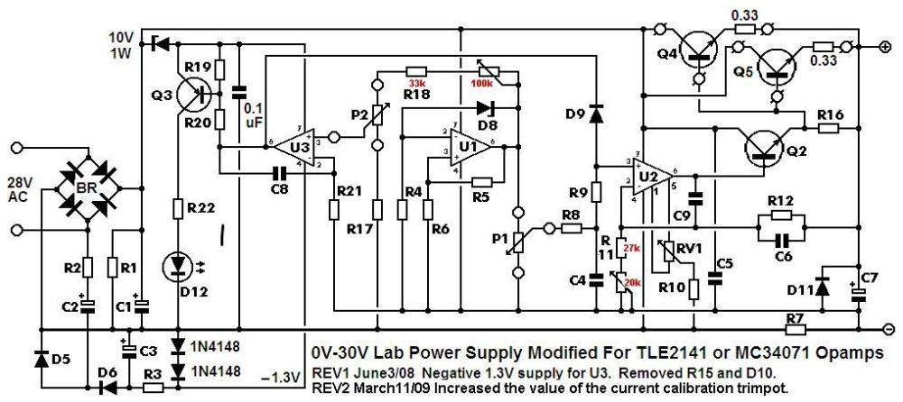
I just wondered if the max voltage out will be low because of the 10v zenner next to q3?.
-
FET-MX8MP-SMARC System on Module(SoM) is developed based on the NXP i.MX 8M Plus processor, focusing on machine learning, vision, advanced multimedia, and highly reliable industrial automation. It caters to applications such as smart cities, industrial IoT, smart healthcare, and intelligent transportation. With powerful quad-core or dual-core ARM® Cortex®-A53 reaching up to 1.6GHz and an NPU achieving 2.3 TOPS, it integrates ISP and dual camera inputs for efficient advanced vision systems. Multimedia features include video encoding (including H.265) and decoding, 3D/2D graphics acceleration, and various audio and voice functions. Real-time control is achieved through Cortex-M7, with a powerful control network using CAN-FD and dual Gigabit Ethernet, supporting Time-Sensitive Networking (TSN). It features high-speed communication interfaces such as 2 x USB 3.0, 1x PCIe 3.0, and 1x SDIO 3.0, meeting the requirements of 5G networks, high-definition video, dual-band WiFi, high-speed industrial Ethernet, and other applications. Explore more about this SoM now! https://www.forlinx.net/product/imx8mpq-smarc-system-on-module-153.html
-
 Thanks for sharing it, I will surely check it.
 -
JamesMVictoria reacted to a post in a topic:
Integrating DHT11 with Beetle ESP32 C3 and Home Assistant
-
 This is a rather complicated process, you will have to look for it.
 -

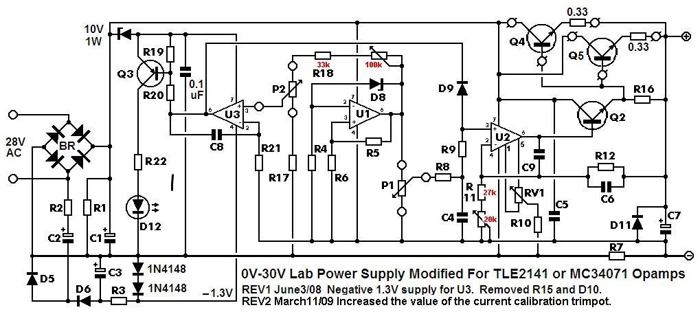
Guitar Level To RCA Line Level Preamp
Paul Bober replied to Paul Bober's topic in Electronic Projects Design/Ideas
My apologies to the Electronics-Lab Community. I should have sent this version of my schematic for the Guitar Level To RCA Line Level Preamp. In this version of the schematic, a 5K feedback resistor is used on A2. This schematic also looks more symmetrical.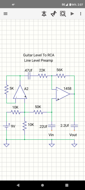
-
anyone?.
-
1. LVDS Interface Specification Forlinx Embedded OK6254-C development board provides 2 x 4-lane LVDS display serial interfaces supporting up to 1.19Gbps per lane; the maximum resolution supported by a single LVDS interface is WUXGA (1920 x 1200@60fps, 162MHz pixel clock). In addition, the interface supports the following three output modes: (1) Single-channel LVDS output mode: at this time, only 1 x LVDS interface displays output; (2) 2x single-channel LVDS (copy) output mode: in this mode, 2 x LVDS display and output the same content; (3) Dual LVDS output mode: 8-lane data and 2-lane clock form the same display output channel.Forlinx Embedded OK6254-C development board is equipped with dual asynchronous channels (8 data, 2 clocks), supporting 1920x1200@60fps. All signals are by default compatible with Forlinx Embedded's 10.1-inch LVDS screen, with a resolution of 1280x800@60fps. 2. Output Mode Setting (1) Single LVDS output mode: We need a single LVDS screen cable. The black port of the cable is connected to the embedded OK6254-C development board, and the white port is connected to the embedded 10.1-inch LVDS display screen. Connection method as shown in the figure below: Note that the red line section corresponds to the triangle position, so don't plug it in wrong. (2) 2x single LVDS (duplicate) output mode: This mode uses the same connections as the Single LVDS Output Mode. Two white ports link to two 10.1-inch LVDS screens from Forlinx Embedded, and a black port on the right connects to the OK6254-C board's LVDS interface for dual-screen display. (3) Dual LVDS output mode: The maximum resolution supported by a single LVDS interface on the OK6254-C development board is WUXGA (1920 x 1200@60fps). To achieve this high-resolution display output, dual LVDS output mode is required. It is worth noting that the connection between the development board and the screen in this mode is the same as in [Single LVDS Output Mode], but the LVDS cable's and the screen's specifications have been improved. 3. Screen Resolution Changing Method OK6254-C development board device tree is easy to modify, we need to open the OK6254-C-lvds.dts (single 8-way configuration) and OK6254-C-lvds-dual.dts (dual 8-way configuration) files. Open OK6254-C-lvds.dts Open OK6254-C-lvds-dual.dts The above figure is the single LVDS and dual LVDS screen resolution information, the default resolution of 1024 * 600, and the maximum resolution support of 1920x1200, you can modify the corresponding parameters according to the Screen User’s Manual. 4. Compilation Configuration Because we only modified the device tree, we don't need a full compilation. After compiling the kernel, a new Image and multiple device tree files will be generated in the images directory. Here we only need to compile the kernel separately. (1) Switch directory: cd OK6254-linux-sdk/ (2) Execution environment variables:.. build.sh (3) Execute the instructions that compile the kernel separately: sudo./build. Sh kernel. (4) Pack all the device tree files to the development board /boot/ directory and replace them, then sync save and reboot scp images/OK6254-C* [email protected]:/boot/ We have modified the corresponding file. How should we select the screen after replacing it? At present, there are three kinds of screen switching control methods: kernel device tree designation, Uboot menu dynamic control, Forlinx Desktop interface and Uboot menu application. Today, I will briefly introduce the dynamic control of Uboot menu. During Uboot, pressing the space bar will take you to the Uboot menu. There are three options in the menu: Enter 0 to enter the Uboot command line; Enter 1 to restart Uboot; Enter 2 to enter the Display Configuration menu. There are three options in the menu: Enter 0 to return to the previous menu; Enter 1 will toggle what option 1 displays to configure Screen 1 LVDS; Note: Screen 1 supports single LVDS, dual LVDS, and off (i.e., LVDS off) Enter 2 to toggle the display of option 2 to configure the Screen 2 LCD. Note: Screen 2 supports 1024 * 600 resolution LCD screen, 800 * 480 resolution LCD screen and off (i.e. RGB off) When selecting the LVDS screen, we enter 1 to select single 8-channel LVDS or dual 8-channel LVDS. After selecting the desired configuration, enter 0 to return to the previous menu level. Restart Uboot or enter the command line to start the system, which can make the screen settings take effect. For other resolution screens, please modify the kernel device tree screen parameters according to the screen parameter requirements.