All Activity
- Today
-
 【实体公司】QQ/微信751558146办理毕业证,成绩单,教育部学历学位认证,使馆认证,归国人员证明,修改成绩单+信封申请学校,offer录取通知书,在读证明,普利茅斯大学学位证书,Plymouth毕业文凭。 ★★主营项目: ◆办理真实使馆公证(即留学回国人员证明,免费申请货后付款,不成功不收费!!!) ◆办理教育部国外学历学位认证。(网上可查、永久存档、快速稳妥,回国发展,考公务员,落户,进国企,外企,创业,无忧愁) ◆办理各国各大学文凭(世界名校一对一专业服务,可全程监控跟踪进度) ◆提供整套申请学校材料 ◆可以提供钢印、水印、烫金、激光防伪、凹凸版、最新版的普利茅斯大学毕业证、百分之百让您绝对满意、设计,印刷,DHL快递;毕业证、成绩单7个工作日,真实大使馆教育部认证2个月。 【真实可查】---【永久存档】---【安全可靠】---【值得信赖】 八年从业经验,专业指导,私人定制,倾心为您解决留学毕业回国各种疑难问题 <1>教育部学历学位认证服务: 做到真实永久存档,网上轻易可查,绝对对客户的资料进行保密,登录核实后再付款。 <2>为什么您的学位需要在国内进一步认证? 二:留信认证的作用 1:该专业认证可证明留学生真实留学身份。 2:同时对留学生所学专业等级给予评定。 3:国家专业人才认证中心颁发入库证书 4:这个入网证书并且可以归档到地方 5:凡是获得留信网入网的信息将会逐步更新到个人身份内,将在公安部网内查询个人身份证信息后,同步读取人 才网入库信息。 6:个人职称评审加20分。 7:个人信誉贷款加10分。 8:在国家人才网主办的全国网络招聘大会中纳入资料,供国家500强等高端企业选择人才。
 -
【实体公司】QQ/微信751558146办理毕业证,成绩单,教育部学历学位认证,使馆认证,归国人员证明,修改成绩单+信封申请学校,offer录取通知书,在读证明,普利茅斯大学学位证书,Plymouth毕业文凭。 ★★主营项目: ◆办理真实使馆公证(即留学回国人员证明,免费申请货后付款,不成功不收费!!!) ◆办理教育部国外学历学位认证。(网上可查、永久存档、快速稳妥,回国发展,考公务员,落户,进国企,外企,创业,无忧愁) ◆办理各国各大学文凭(世界名校一对一专业服务,可全程监控跟踪进度) ◆提供整套申请学校材料 ◆可以提供钢印、水印、烫金、激光防伪、凹凸版、最新版的普利茅斯大学毕业证、百分之百让您绝对满意、设计,印刷,DHL快递;毕业证、成绩单7个工作日,真实大使馆教育部认证2个月。 【真实可查】---【永久存档】---【安全可靠】---【值得信赖】 八年从业经验,专业指导,私人定制,倾心为您解决留学毕业回国各种疑难问题 <1>教育部学历学位认证服务: 做到真实永久存档,网上轻易可查,绝对对客户的资料进行保密,登录核实后再付款。 <2>为什么您的学位需要在国内进一步认证? 二:留信认证的作用 1:该专业认证可证明留学生真实留学身份。 2:同时对留学生所学专业等级给予评定。 3:国家专业人才认证中心颁发入库证书 4:这个入网证书并且可以归档到地方 5:凡是获得留信网入网的信息将会逐步更新到个人身份内,将在公安部网内查询个人身份证信息后,同步读取人 才网入库信息。 6:个人职称评审加20分。 7:个人信誉贷款加10分。 8:在国家人才网主办的全国网络招聘大会中纳入资料,供国家500强等高端企业选择人才。
-
heziruo8871 joined the community
-
Students need MBA essay writing services to craft compelling and polished essays that stand out in competitive admissions processes. These services provide expert guidance, ensuring essays are well-structured, articulate, and showcase the applicant's strengths and aspirations. For top-notch support, students can rely on MBA essay writing help at https://allessaywriter.com/mba-essay-writing-service.html, which offers personalized assistance to enhance their chances of acceptance.

-
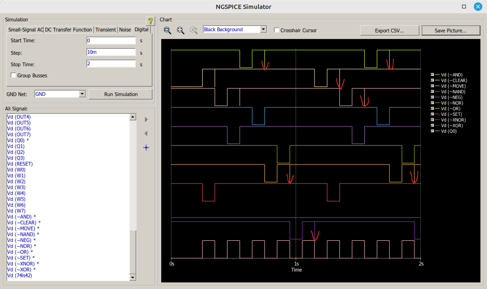
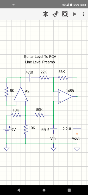
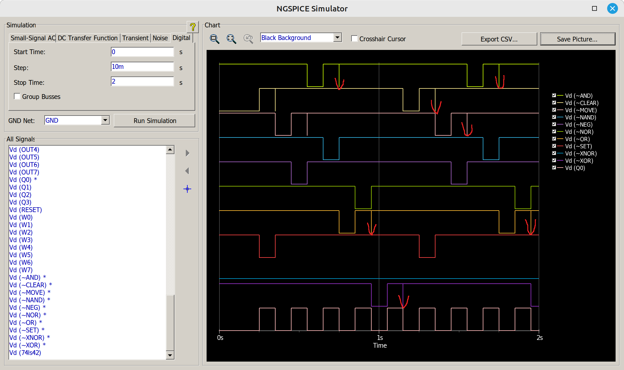
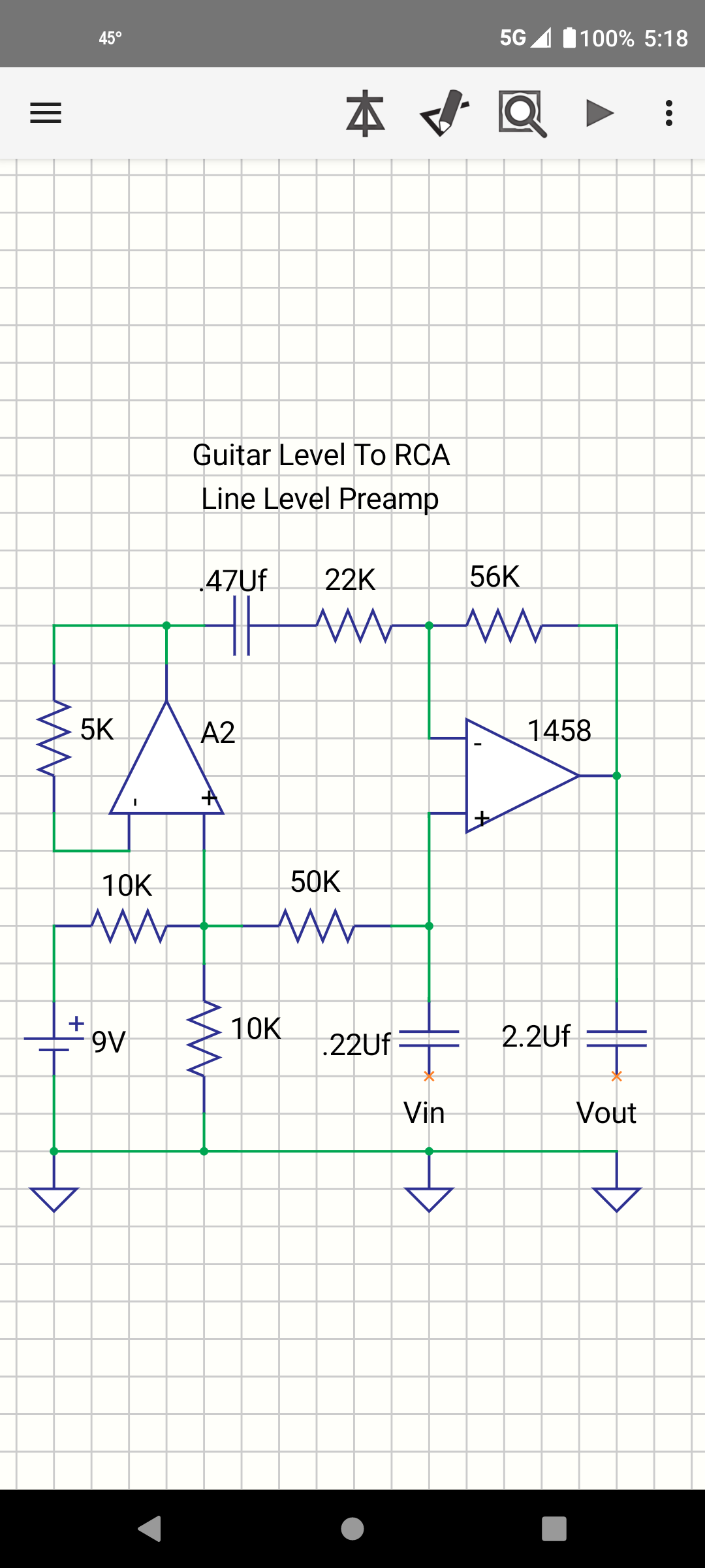
I have created a schematic, see the attached screenshot. Now I am trying to simulate how it works in a digital SPICE simulator (built-in DipTrace 5.0 beta). In general, it works almost reasonably. But there are strange signal distortions on some outputs of U3 on each falling edge of the clock coming to the input of decade counter U5. I have shown the problem with red marks. What I am doing wrong? Is it a simulator issue or the schematic is incorrect?

-
 Denna200 joined the community
 - Yesterday
-
 RenoX023 joined the community
 - Last week
-
 Arij Fraj joined the community
 -
In this tutorial, I will guide you on how to create a temperature and humidity monitoring system that can be controlled by voice using a FireBeetle and a DHT11 sensor. Imagine being able to ask your FireBeetle about the current temperature and getting a visual response! Let's dive into the details. 💡 Components Required: DFRobot FireBeetle 2 ES32 S3 DHT11 Temperature and Humidity Sensor DFRobot Gravity Offline Voice Recognition sensor Jumper Cables 🔌 Wiring Diagram: Connect the DHT11 sensor to the FireBeetle as follows: GND pin: Connect to GND (0V). VCC pin: Connect to VCC (5V or 3.3V). DATA pin: D5 If you’re using a DHT11 module, it may have a built-in resistor, eliminating the need for an external one. Connect the Offline Voice Recognition sensor to the FireBeetle as follows: GND pin: Connect to GND (0V). VCC pin: Connect to VCC (5V or 3.3V). DATA pin: SDA CLOCK pin:SCL Finally, connect the TFT screen to the FireBeetle directly via the connector interface. Get PCBs for Your Projects Manufactured You must check out PCBWAY for ordering PCBs online for cheap! You get 10 good-quality PCBs manufactured and shipped to your doorstep for cheap. You will also get a discount on shipping on your first order. Upload your Gerber files onto PCBWAY to get them manufactured with good quality and quick turnaround time. PCBWay now could provide a complete product solution, from design to enclosure production. Check out their online Gerber viewer function. With reward points, you can get free stuff from their gift shop. Also, check out this useful blog on PCBWay Plugin for KiCad from here. Using this plugin, you can directly order PCBs in just one click after completing your design in KiCad. 1️⃣ Train the custom voice commands: This DFRobot Gravity Offline Voice Recognition Sensor sensor is designed for Arduino, Raspberry Pi, Python, and ESP32 platforms. It allows you to recognize voice commands without an internet connection and comes with built-in fixed command words as well as the ability to add custom commands. Here are the steps to train custom voice commands: First, connect the Voice Recognition sensor's VCC pin to 5V and GND to GND. Then wake up the sensor by saying "Hello Robot" Next, say "Learning command word", this will help us to add our own command words. Once the system ready, train with your custom commands. Here I have created two commands, one is what is the temperature? and the next one is what is the humidity? These commands have some specific ID. Normally the first command id is 5 then the following will be 6,7 and so on. In my case what is the temperature? is command is 5 and what is the humidity? is command is 6. 2️⃣ Install Required Libraries: In your Arduino IDE or other development environment, install the necessary libraries for the Gravity Voice Recognition Sensor. You can find the library on the DFRobot GitHub repository. As well as the DHT11 sensor. 3️⃣ Programming the FireBeetle: Write a program to interface with the sensor. You can use the provided example code or create your own. This code will get the DHT11 temp and humidity value. #include <dht11.h> dht11 DHT; #define DHT11_PIN 4 void setup(){ Serial.begin(9600); Serial.println("DHT TEST PROGRAM "); Serial.print("LIBRARY VERSION: "); Serial.println(DHT11LIB_VERSION); Serial.println(); Serial.println("Type,\tstatus,\tHumidity (%),\tTemperature (C)"); } void loop(){ int chk; Serial.print("DHT11, \t"); chk = DHT.read(DHT11_PIN); // READ DATA switch (chk){ case DHTLIB_OK: Serial.print("OK,\t"); break; case DHTLIB_ERROR_CHECKSUM: Serial.print("Checksum error,\t"); break; case DHTLIB_ERROR_TIMEOUT: Serial.print("Time out error,\t"); break; default: Serial.print("Unknown error,\t"); break; } // DISPLAT DATA Serial.print(DHT.humidity,1); Serial.print(",\t"); Serial.println(DHT.temperature,1); delay(2000); } Here is the complete sketch to configure DHT11 for voice recognition. #include <Wire.h> #include "DFRobot_GDL.h" #define TFT_DC D2 #define TFT_CS D6 #define TFT_RST D3 #include <DFRobot_DHT11.h> DFRobot_DHT11 DHT; #define DHT11_PIN D5 DFRobot_ST7789_240x320_HW_SPI screen(/dc=/TFT_DC,/cs=/TFT_CS,/rst=/TFT_RST); #include "DFRobot_DF2301Q.h" //I2C communication DFRobot_DF2301Q_I2C DF2301Q; void setup() { Serial.begin(115200); screen.begin(); Wire.begin(); // Init the sensor while ( !( DF2301Q.begin() ) ) { Serial.println("Communication with device failed, please check connection"); delay(3000); } Serial.println("Begin ok!"); DF2301Q.setVolume(7); DF2301Q.setMuteMode(0); DF2301Q.setWakeTime(15); uint8_t wakeTime = 0; wakeTime = DF2301Q.getWakeTime(); Serial.print("wakeTime = "); Serial.println(wakeTime); DF2301Q.playByCMDID(23); // Common word ID } void loop() { uint8_t CMDID = 0; CMDID = DF2301Q.getCMDID(); c if (0 != CMDID) { Serial.print("CMDID = "); Serial.println(CMDID); int16_t color = 0x00FF; screen.setTextWrap(false); screen.setRotation(1); screen.fillScreen(COLOR_RGB565_BLACK); screen.setTextColor(COLOR_RGB565_GREEN); screen.setFont(&FreeMono9pt7b); screen.setTextSize(1.5); screen.setCursor(0, 30); screen.println("CNID: "); screen.setCursor(130, 30); screen.setTextColor(COLOR_RGB565_RED); screen.println(CMDID); if (CMDID == 5) { Serial.print("CMDID = "); Serial.println(CMDID); DHT.read(DHT11_PIN); Serial.print("temp:"); Serial.print(DHT.temperature); Serial.print(" humi:"); Serial.println(DHT.humidity); int16_t color = 0x00FF; screen.setTextWrap(false); screen.setRotation(1); screen.fillScreen(COLOR_RGB565_BLACK); screen.setTextColor(COLOR_RGB565_GREEN); screen.setFont(&FreeMono9pt7b); screen.setTextSize(1.8); screen.setCursor(20, 50); screen.println("Tempearature: "); screen.setTextColor(COLOR_RGB565_RED); screen.setCursor(160, 50); screen.println(DHT.temperature); screen.setCursor(190, 50); screen.println(" C"); } if (CMDID == 6) { Serial.print("CMDID = "); Serial.println(CMDID); DHT.read(DHT11_PIN); Serial.print("temp:"); Serial.print(DHT.temperature); Serial.print(" humi:"); Serial.println(DHT.humidity); int16_t color = 0x00FF; screen.setTextWrap(false); screen.setRotation(1); screen.fillScreen(COLOR_RGB565_BLACK); screen.setTextColor(COLOR_RGB565_GREEN); screen.setFont(&FreeMono9pt7b); screen.setTextSize(1.8); screen.setCursor(20, 50); screen.println("Humidity: "); screen.setTextColor(COLOR_RGB565_RED); screen.setCursor(160, 50); screen.println(DHT.humidity); screen.setCursor(190, 50); screen.println(" %"); } } delay(1000); } 4️⃣ Testing and Refinement: Upload your program to the FireBeetle, select the correct COM port, and wait until it finishes the upload. Test the sensor by speaking the fixed command words and your custom commands. And look at the serial terminal for the response. Finally, you can see the DHT11 data on the TFT screen. 5️⃣ Use in Your Project: Now that your sensor recognizes custom voice commands, integrate it into your project. For instance, control home automation devices, trigger specific actions, or create interactive audio experiences. Remember that the sensor’s self-learning function allows you to train it with various sounds, not just voice. So, get creative! You can use whistles, snaps, or even cat meows as custom commands. 🎙️🔊 For more detailed information, refer to the DFRobot Wiki and explore the Hackster project. Happy hacking! 🚀
-
 abir1 joined the community
 -
 Eric Seaman changed their profile photo
 -
 Anto Jenish Baskar J joined the community
 -
 csmith joined the community
 -
Hall Sensor Bypass for Coffee Grinder
csmith replied to millicurie999's topic in Electronic Projects Design/Ideas
I have a slightly different issue and that is my coffee grinder only grinds for 1/2 the required time. I have two of these machines (one decaf on caf) and if you time the grind cycle, one of them is exactly half the time of the other and brews too weak a cup of coffee. It may be this sensor but why would it be double counting rotations? -
 Wesam Rohouma joined the community
 -
Hi, It's a very good project. Using the voice recognition module needs a lot of expertise, no doubt. However, you can give your project a more compact look and better build. You are using a breadboard. It can create problems. sometimes one or two wires may disconnect. You can print a PCB instead. For example, like this one: https://www.pcbway.com/project/shareproject/Voice_Controlled_Door_Lock_using_Alexa_and_Arduino_7cf9dadf.html As you can see, this is also a voice controlled project. It has an on board Arduino Nano IoT 33. You can make a board like this using Beetle ESP32 C microcontroller, voice recognition module and neopixel.
-

MOSFET Power module and gate drive connections guidance
Huxley Morris replied to mumartahir's topic in Power Electronics
wow -
 โต้ จูนเนอร์ ขอนแก่น changed their profile photo
 -
 Fajar Nur Prasetyo changed their profile photo
 -
Hi, everyone! I’m a student, and I really like electronic products. It’s an honor to meet everyone in this forum. I want to learn more about electronics and make new friends here. I hope we can communicate and share knowledge in the future. Looking forward to our common progress! By the way, if you enjoy exploring new things, you might want to check out some low-deposit online casinos. At https://casinoofthekings.ca/low-deposit-casino/1-deposit/, you can find great options to start playing with just a small deposit. It’s an easy and affordable way to enjoy some online gaming. Looking forward to our discussions and learning together!
-
 Software version: Linux 4.19 Design Idea: Detect screen touch events to determine whether the screen is being used or not in an auto-break application. If the screen detects input events, it will remain on. If no touch events are received for a period of time, the screen will transition from on to a dimmed state, reminding the user that it is about to enter the screen-off mode. If no touch events occur after dimming, the screen will enter the screen-off mode. When a touch event occurs again, the screen will transition from screen-off mode to the on state. Currently, the approach to implement automatic screen-off is to treat touch events as a fixed path that can be applied to familiar boards. To enhance convenience in application, two additional alternative approaches are provided below: ▊ The first implementation method You can apply the evtest command to get the path to/dev/input/event1 (event1 is the name of the touch event on my board). You can then pass the path to your program as a parameter. For example, you can modify your program to accept command-line arguments to specify the path of the device file to open int argc, char *argv[]; Opens a file with the passed in parameters as the device file path int fd = open(argv[1], O_RDONLY); You can compile and run the program, passing it/dev/input/event1 as a command-line argument, like this: ./your_program /dev/input/event1 ▊ The second implementation method is to fix the screen touch node in the device tree. Look for the screen touch node in the device tree and note its address. On the I2C bus, the address of the touch node is simply 2-0038 So we can use grep to filter out touch nodes based on their addresses. ls -l /sys/class/input | grep "0038" | awk -F ' ' '{print $9}' | grep "event" The following command is used in the application to find the touch event based on the touch address. char *command_output = exec("ls -l /sys/class/input | grep '0038' | awk -F ' ' '{print $9}' | grep 'event'"); Use the sprintf function to splice the path containing the event, and then read the event. Examples of using Sprintf: int main() { char str[100]; int num = 123; float f = 3.14; //Write the formatted data to the string sprintf(str, "%d%.2f", num, f); //print the generated string printf("The output is. %s\n", str); return 0; }
 -
 Asmat Ullah Khan changed their profile photo
 -
 CHANDRASEKHAR M changed their profile photo
 -
 queenabee jin changed their profile photo
 -
Some customers rely on battery power for their products and have limited battery capacity. If a screen is used in the product, the screen will be one of the main sources of energy consumption. Therefore, turning off the screen in time can effectively extend the battery life and improve the user experience. In addition, the auto-screen-off function not only extends the life of the screen but also effectively prevents the risk of information leakage and privacy exposure. Generally speaking, the automatic screen off function plays an important role in improving the performance of the device, saving energy and protecting privacy. Knowledge points involved: 1. Struct input _ event: a data structure used to represent Linux input event This structure usually contains various information of the input event, such as event type, event code, value, etc. When dealing with input devices such as keyboards and mice, you can use this structure to store and pass information about input events. Specifically, the struct input _ event structure typically contains the following fields: Struct timeval time: The timestamp of the event occurrence. Unsigned short type: The type of event (e.g., key press, release, etc.) Unsigned short code: Code of the event (such as which key was pressed). Int value: The value of the event (key press/release, etc.) By defining such a structure, it is easy to package together the various attributes of an input event for processing and passing in the program. When reading the events of the input device, this structure can be used to store the specific information of each event, which is convenient for subsequent analysis and response to the input events. 2. Functions and differences of read function and select function The read () function and the select () function are both functions used in Linux systems to handle I/O operations, but there are some differences in what they do and how they are used. (1)Read () function: The read () function is used to read data from a file descriptor, such as a file, socket, and so on.It is a blocking system call, that is, when there is no data to read, the program will be blocked until there is data to read or an error. The read () function reads data from the file descriptor into the specified buffer and returns the actual number of bytes read, or -1 if an error occurs. (2)Select () function: The select () function monitors multiple file descriptors to determine whether they are in a readable, writable, or abnormal state. Through the select () function, multiplexing can be achieved, that is, one of multiple file descriptors is selected for I/O operation without blocking and waiting. The select () function blocks the process until at least one of the specified file descriptors is in a readable, writable, or exception state, or the specified timeout has passed. The select () function is usually used to listen to multiple file descriptors at the same time, so that when any file descriptor is ready, the corresponding read and write operations can be performed to improve the efficiency of the program. In summary, the read () function is a blocking operation to read data from a single file descriptor, while the select () function is a function to multiplex the state of multiple file descriptors to help the program manage multiple I/O operations more efficiently. The select () function is typically used in situations where you need to listen to multiple file descriptors at the same time. In the program, events are read from the input device through the read () function. If no event is reported, the read () function blocks the program and does not return until an event occurs or an error occurs. Therefore, if there is no event reported, the program will stay at the read () function and will not perform subsequent printing operations. If an event is reported, the read() function reads the event data and returns the number of bytes of the event. In this case, the program performs a subsequent print operation to print out the event information. This is why messages are printed only when there is an event reported and not when there is no event reported. To print the information even if no event is reported, you can set a timeout before reading the event. If no event is reported within the timeout period, the prompt information will be printed. This can be done using the select() function. In this modified code, we use the select() function to wait for the file descriptor to be ready for a read operation, and if it is not ready within the timeout period, it returns 0, at which point we print "No event reported within 1 second". If ready, read the event and print the appropriate message. This will print a reminder message every 1 second even if no events are reported. 3. Character devices for /dev/disp Switch for controlling display device The method of operation of a string device is disp _ fops: In fact, only two functions, disp _ ioctl () and disp _ mmap (), have concrete implementations.ioctl can refer to: "T507_Display_Module_Use_Documentation.pdf". 4. Sleep Mode / /sys/power/state freeze freeze: In the Freeze sleep state, the system will suspend CPU operation, but memory and devices will remain active to resume working faster. Mem: In the Mem sleep state, the system saves everything to memory and turns off unnecessary devices to save power. The CPU stops running, and the memory and some necessary devices continue to be active. In general, the freeze sleep state is relatively shallow, and the system can recover to the working state more quickly, but the power consumption is relatively high, while the mem sleep state is deeper, and the power consumption is lower, but the recovery time may be slightly longer. According to the actual needs and system requirements, the appropriate sleep state can be selected to balance power consumption and performance.
-
 ali kiani changed their profile photo
 -
Hellow guys, sorry then Can I get how these projects can be made, please.... 1. Design a circuit that removes the entire audio frequency range (approximately 20Hz to 20kHz, for human hearing) but amplifies the signal voltage of all other frequencies by a factor of 20. 2. Depending on which song you are listening to, your MP3 player sometimes provides too little bass, even when the appropriate setting is maximized. Design a filter that allows you to vary the gain real-time of all signals less than 500Hz before reaching your earphones. Include a diagram of the overall system
- Earlier
-
 Davis Yazmin changed their profile photo
 -
 Gustas Borisovas changed their profile photo
 -
 Sudheendra Varna changed their profile photo
 -
 In the world of embedded systems and IoT devices, power consumption is a critical factor that can make or break the success of a product. The Nordic Power Profiler Kit II (PPK 2) is an indispensable tool for developers looking to optimize the power usage of their devices. While the official nRF Connect Power Profiler provides a user-friendly GUI, there’s a growing need for automation in power monitoring. This is where Python comes into play, offering a way to control PPK 2 programmatically. Unofficial Python API for PPK 2 An unofficial Python API for PPK 2 has been developed to fill the gap left by the official tool. This API allows for automated power monitoring and data logging within Python applications, making it possible to integrate power profiling into automated test environments. Key Features Real-time power measurement: The API enables real-time measurement of device power consumption, which is crucial for identifying power spikes and optimizing energy usage. Data logging: It supports data logging in user-selectable formats, allowing for long-term power consumption analysis. Cross-platform support: The API is designed to work across different platforms, ensuring that developers can use it regardless of their operating system. Get PCBs for Your Projects Manufactured You must check out PCBWAY for ordering PCBs online for cheap! You get 10 good-quality PCBs manufactured and shipped to your doorstep for cheap. You will also get a discount on shipping on your first order. Upload your Gerber files onto PCBWAY to get them manufactured with good quality and quick turnaround time. PCBWay now could provide a complete product solution, from design to enclosure production. Check out their online Gerber viewer function. With reward points, you can get free stuff from their gift shop. Also, check out this useful blog on PCBWay Plugin for KiCad from here. Using this plugin, you can directly order PCBs in just one click after completing your design in KiCad. Let's start with UNIHIKER: The UNIHIKER is a single-board computer that boasts a 2.8-inch touchscreen, providing a tactile and visual interface for your applications. It’s powered by a Quad-Core ARM Cortex-A35 CPU and comes with 512MB RAM and 16GB Flash storage. The board runs on Debian OS, ensuring a familiar and versatile environment for Linux enthusiasts In this tutorial, we are going to automate the power profiling with the UNIHIKER Single Board Computer. Install Python API in UNIHIKER: Connect UNIHER to the PC and open the Mind+ IDE. Next, connect the UNIHIKER to Mind+ via serial port. Next, run the following command in the terminal and install the ppk2 library. pip install ppk2-api Now you can see the zip file in the UNIHIKER file storage. Once installed, you can start by importing the necessary classes and initializing the PPK2_API object with the appropriate serial port. Here’s a basic example to get you started: import time from ppk2_api.ppk2_api import PPK2_API # Initialize the PPK2_API object with the correct serial port ppk2_test = PPK2_API("/dev/ttyACM3") # Replace with your serial port # Set up the power profiler ppk2_test.get_modifiers() ppk2_test.use_source_meter() # Set source meter mode ppk2_test.set_source_voltage(3300) # Set source voltage in mV # Start measuring ppk2_test.start_measuring() # Read measured values in a loop for i in range(0, 1000): read_data = ppk2_test.get_data() if read_data != b'': samples = ppk2_test.get_samples(read_data) print(f"Average of {len(samples)} samples is: {sum(samples)/len(samples)}uA") time.sleep(0.001) # Adjust time between sampling as needed # Stop measuring ppk2_test.stop_measuring() This script sets the PPK 2 to source meter mode, starts measuring, and prints out the average current consumption over several samples. It’s a simple yet powerful way to begin automating power profiling for your projects. Demo Let's unzip the zip file and open the folder so that you can see the example sketches. here is the example script. In this sketch, it will automatically detect the connected PPK2 devices and it will power up the DUT as well as measure the 100 samples. import time from ppk2_api.ppk2_api import PPK2_API from unihiker import GUI # Import the unihiker library import time # Import the time library from pinpong.board import Board # Import the Board module from the pinpong.board package from pinpong.extension.unihiker import * # Import all modules from the pinpong.extension.unihiker package ppk2s_connected = PPK2_API.list_devices() if(len(ppk2s_connected) == 1): ppk2_port = ppk2s_connected[0] print(f'Found PPK2 at {ppk2_port}') else: print(f'Too many connected PPK2\'s: {ppk2s_connected}') exit() ppk2_test = PPK2_API(ppk2_port, timeout=1, write_timeout=1, exclusive=True) ppk2_test.get_modifiers() ppk2_test.set_source_voltage(3300) ppk2_test.use_source_meter() # set source meter mode ppk2_test.toggle_DUT_power("ON") # enable DUT power ppk2_test.start_measuring() # start measuring for i in range(0, 100): read_data = ppk2_test.get_data() if read_data != b'': samples, raw_digital = ppk2_test.get_samples(read_data) print(f"Average is:{sum(samples)/len(samples)}uA") final=sum(samples)/len(samples) time.sleep(0.01) ppk2_test.toggle_DUT_power("OFF") # disable DUT power ppk2_test.stop_measuring() Conclusion The Nordic PPK 2, combined with the power of Python and UNIHIKER, opens up new possibilities for automated power profiling. Whether you’re looking to integrate power profiling into your CI/CD pipeline or simply want to streamline your testing process, the unofficial Python API for PPK 2 is a valuable addition to your toolkit. I hope this blog post provides a clear overview of how to control the Nordic Power Profiler Kit II with Python and UNIHIKER. If you have any questions or need further assistance, feel free to ask!
 -
 chris acob reacted to a post in a topic:
Fridge Protection
chris acob reacted to a post in a topic:
Fridge Protection
-
The UNL2003 IC contains 7 High Voltage, High Current NPN Darlington Transistor Arrays each rated at 50V, 500mA in a 16-pin DIP package. You can connect the IC directly to a digital logic (like Arduino or Raspberry Pi, TTL or 5V CMOS device) without an external dropping resistor. This IC features "common-cathode flyback diodes" for switching inductive loads. The ULN2003 is known for its high current and high voltage capacity. The Darlington pairs can be "paralleled" for higher current Output. The inputs are capable with TTL and 5v CMOS logic. Now, let's deep-dive and check out the internals of the IC and how it can be used in our projects. Pin Configuration and Functions The notch on the top indicates the starting and stopping points of the numberings of the chip. Starting from left to right going counterclockwise this is the Pin number 1 of the IC. * On the left hand side Pin 1 to 7 are the Base Inputs. * On the right hand side Pin 10 to 16 are the Collector Outputs. * Pin 9 is the Common Cathode node for flyback diodes (required for inductive loads). * And, Pin 8 is the Common Emitter shared by all channels of the IC. This pin is typically tied to ground. Detailed Description Inside the IC is the arrays of the 7 NPN "Darlington Transistors". Darlington Transistors were first invented in 1953 by Sidney Darlington. A Darlington pair is a circuit consisting of two Bipolar Transistors with the Emitter of one transistor connected to the Base of the other transistor. In this setup, the current amplified by the first transistor is further amplified by the second transistor. The collectors of both transistors are connected together. This configuration has a much higher current gain than each transistor taken separately. A small base current can make the pair switch to a much higher current. It appears as if it is just a single transistor, with only one base, one collector, and one emitter. Creating a high current gain approximately to the product of the gains of the two transistors: β Darlington = (β 1 * β 2) + β 1 + β 2 Since, β1 and β2 are high enough, we can write the above statement as: β Darlington ≈ β 1 * β 2 This connection creates the effect of a single transistor with a very high-current gain. The 7 outputs are all "Open Collector". By Open Collector, we mean a collector that is not attached to anything. It's just open. In order for an open collector output device to work, the open collector has to receive sufficient power. In order for an NPN transistor to work, the collector and the base both need to receive sufficient power. The base turns the transistor on, and then a much greater current flows from collector to emitter, but only if the collector has sufficient positive voltage. So if you want to connect a load to the Output of the chip with an open-collector-output, you must attach the load to a positive voltage source that is sufficient enough to drive the load. Hence, the +ve side of the load connects to the +ve voltage rail and the -ve side connects to the OUTPUT pin of the IC. Hence, when the Base current goes HIGH, the current flows from the collector to emitter and the Output logic goes LOW turning ON the LED (load) connected to the OUT pin of the IC and vice-versa. The maximum Output Current of a single OUTPUT pin is 500mA and the total emitter-terminal current is 2.5A as per the datasheet. Now, let's have a closer look at a single Darlington pair (internal circuit diagram) of the ULN2003 IC. The GPIO input voltage is converted to base current through a series base 2.7kΩ resistor connected between the Input and Base of the Darlington NPN junction. This allows the IC to connect directly to a digital logic (like Arduino, Raspberry Pi, TTL or 5V CMOS device) without the need of external dropping resistors operating at supply voltages of 5V or 3.3V. The 7.2kΩ and the 3kΩ resistors connected between the Base and the Emitter of each respective NPN transistor acts as pulldown resistors preventing floating states and suppressing the amount of leakage that may occur from the input. To maximize the effectiveness, these units contain "Suppression Diodes" for inductive loads. The diode connected between the OUT pin and the COM pin (PIN 9) is used to suppress the "kick-back voltage" from an inductive load which is generated when the NPN drivers are turned off and the stored energy of the coils causes a reverse flow of current. A reverse biased suppressing diode is also placed between the Base-Emitter and the Collector-Emitter pair to avoid the Parasitic nature of the NPN transistors. Pin 8 is connected to the GND. Device Functional Modes Inductive Load In case of an inductive load, when the COM pin is tied to a coil, the IC is able to drive inductive loads and suppress the kick-back voltage through the internal free-wheeling diodes. Resistive Load When driving a resistive load, a pullup resistor is needed in order for the IC to sink current and maintain a logic HIGH level. In this case the COM pin can be left floating (not connected). This device can operate over a wide temperature range between –40°C to 105°C. Applications Now, lets hook this IC to a circuit. As we know, the ULN2003 IC can easily drive a high-current or high-voltage (or both) device, which a Microcontroller or a Logic Device cannot tolerate. Hence, they are widely used in driving inductive loads like motors, solenoids and relays. 1. In my first example, I am going to light up a few LEDs using this IC I have connected 7 LEDs to the 7 OUT Pins of the IC via 220Ohm resistors. On my left, are the 7 digital inputs directly interfaced to either a Microcontroller or a TTL Digital Logic. When a logic HIGH is sent to the input pin the corresponding OUT pin goes LOW lighting up the LED. 2. In my second example, I am driving a Unipolar Stepper Motor using this IC In this setup, I am using Pin 1~4 for INPUT and Pin 13~16 for OUTPUT. Each OUT pin is rated at 500mA. Pin 9 has the spike suppressor diode, and is connected to the +ve terminal. By sending combinations of 0's and 1's to the 4 input pins we can rotate our stepper motor. I have used this setup in my award winning Video Tutorial: "NodeMCU Based - 3D Printed Indoor Gauge Thermometer" the link is in the description below. 3. In my third example, I am going to light-up a few AC Lightbulbs using this IC For high voltage applications, we can use RELAYS to control motors, heaters, lamps or AC circuits which themselves can draw a lot more electrical voltage/current and therefore power. We can hook up a maximum of 7 Relays to this IC. In my setup, I have connected 4 Relays to the 4 OUT pins of the IC. An AC Lightbulb is connected to the NO-pin of the relay. When we send a Digital HIGH to the INPUT pin the corresponding OUT pin goes LOW and current flows through the coil pulling the armature, completing the circuit and hence lighting up the 220V Light Bulb. Same as the previous setup, Pin 9 with the suppressor diode is tied back to the +ve terminal. 4. In my 4th example, I am going to show you guys how to obtain more than 500mA at the OUTPUT As we know that each of the OUT Pins are rated at 500mA, then how can I drive a 1Amp device? All we have to do is, tie 3 of the OUTPUT pins on the OUT side, and tie 3 of the corresponding INPUT Pins on the INPUT side. Now the 3 INPUT pins act like a single INPUT Pin. So basically, we can parallel the inputs to get a higher amplified value of paralleled output. You may ask, why did I combine 3 INPUTS and OUTPUTS and not just 2? As per the datasheet each pin is rated at 500mA but the total output is 2.5A (*** Page 4 of datasheet ****). Hence, 2.5A / 7 Pins = 0.36 Approx. So, 0.36 * 3 = 1.07Amp Approx. which is what we want. Areas of Application The ULN2003A produced by Texas Instruments can be used for: 1. Driving motors and solenoids 2. Can be used as a Relay Driver for high voltage application (7 relays at the max) 3. To drive high current loads using Digital Circuits 4. To drive high current LED's 5. To create a water level indicator circuit 6. As a LED and Gas Discharge Display Drivers 7. Can also be used as a logic buffer in digital circuits and more... For more information about the packaging and the material used, please have a look at the datasheet. The link is in the description below. Always consult a manufacturer's datasheet before assuming industrial conventions, no matter how intuitive or obvious they may be. "In the face of ambiguity, refuse the temptation to guess." - Zen of Python Thanks Thanks again for checking my post. I hope it helps you. If you want to support me subscribe to my YouTube Channel: https://www.youtube.com/user/tarantula3 Video: Watch Full Blog Post: Visit References DataSheet: Download Darlington transistor: View Open Collector Output: View Transistor–Transistor Logic: View Parasitic Structure: View Related Videos NodeMCU Based - 3D Printed Indoor Gauge Thermometer: View Acronyms TTL: Transistor–Transistor Logic CMOS: Complementary Metal–Oxide–Semiconductor Support My Work BTC: 1Hrr83W2zu2hmDcmYqZMhgPQ71oLj5b7v5 LTC: LPh69qxUqaHKYuFPJVJsNQjpBHWK7hZ9TZ DOGE: DEU2Wz3TK95119HMNZv2kpU7PkWbGNs9K3 ETH: 0xD64fb51C74E0206cB6702aB922C765c68B97dCD4 BAT: 0x9D9E77cA360b53cD89cc01dC37A5314C0113FFc3 LBC: bZ8ANEJFsd2MNFfpoxBhtFNPboh7PmD7M2 COS: bnb136ns6lfw4zs5hg4n85vdthaad7hq5m4gtkgf23 Memo: 572187879 BNB: 0xD64fb51C74E0206cB6702aB922C765c68B97dCD4 MATIC: 0xD64fb51C74E0206cB6702aB922C765c68B97dCD4 Thanks, ca again in my next tutorial.
-
Hi am new here, i recently bought the kit, its ok to use schema and part list rev 7 for 3A with two output transistors ? I plan to use a pair of 2N3055 or there is a better choiche ? Thanks
-
Nobody answer what is the equivqalent of BF494,BF495
-
In modern cities, the medical rescue system is crucial for urban safety. Emergency centers command rescue operations, essential for saving lives. With the advancement of IoT technology, many cutting-edge technologies are gradually integrated into the medical emergency system, enabling ambulances to be networked, digitized, and intelligent. Thus, 5G smart ambulances emerge. 5G-enhanced ambulances look similar to regular ones in appearance. However, by integrating 5G networks into the vehicle, developers instantly endowed it with additional "superpowers". For instance, 5G-enhanced ambulances can achieve synchronized transmission of multiple high-definition live videos, leveraging 5G's high bandwidth, low latency, and reliability. Based on this, it can synchronously return the medical images, patient signs, illness records and other information of emergency patients to the hospital emergency center without damage, which is convenient for the emergency center to grasp the patient's condition in advance and give professional guidance to the rescuers on the bus. Forlinx's 5G Smart Gateway FCU2303 provides reliable support for medical ambulance. Rapid transmission of information Bridge the gap for medical device information transmission. Modern ambulances are equipped with advanced medical equipment such as electrocardiogram monitors, ventilators, and defibrillators to enhance rescue efficiency. Various types of diagnostic and therapeutic equipment can efficiently transmit physiological data to the Hospital Information System (HIS) through the multiple Ethernet ports, serial ports, and DI/DO of the FCU2303 industrial-grade smart gateway. This meets the data collection and transmission requirements of ambulances. Enabling high-definition audio and video consultations Medical imaging equipment such as cameras, microphones, displays, and ultrasound machines are deployed on the ambulance. Through the FCU2303 industrial-grade smart gateway, information is transmitted, providing real-time, lossless transmission of audio-visual images from the ambulance to the hospital emergency center. This setup offers a high-bandwidth, low-latency, and highly connected secure network, meeting the remote video consultation needs of the ambulance. It aims to secure more time for patients by implementing a rapid rescue and treatment mode where patients essentially “Be in the hospital” upon boarding the ambulance. Enabling reliable integration of multiple technologies FCU2303 Smart Gateway, designed based on the NXP LS1046A processor, features a quad-core CPU with a high clock frequency of 1.8GHz. With a fanless design, it ensures stable operation of medical rescue systems for extended periods in environments ranging from -40°C to +85°C; It supports 5G and 4G modules, which can be easily switched with a single DIP switch. It provides users with high bandwidth, low latency, and large connectivity services. It also supports dual-band Wi-Fi, enabling both STA and AP modes; FCU2303 supports expandable device storage with PCIe 3.0 high-speed interface, enabling support for solid-state drives (SSDs) using the NVMe protocol (M.2 interface). This meets the requirements for small size, large capacity, and fast speed; It comes standard with 8 x Gigabit Ethernet ports (flexible configuration of 2/4/6/8 ports, all with independent MAC addresses), 4 RS485 ports, 4 RS485/RS232 multiplexing interfaces, 2 DI (Digital Input), 2 DO (Digital Output), and 1 USB HOST 3.0 port. This ensures the connectivity of various medical devices, enabling full vehicle networking for ambulances; The software integrates a variety of third-party components including Samba, Lighttpd, Docker, IPSEC, OpenSSL, and Python 3 or higher versions. It supports protocols such as TCP/IP, UDP, DHCP, TFTP, FTP, Telnet, SSH, Web, HTTP, IPtables, and provides an open system API for easy user customization and development. In the future, smart ambulances based on 5G technology will undoubtedly provide better full-process services for patients, including pre-diagnosis, during diagnosis, and post-diagnosis. Forlinx Embedded FCU2303 Smart Gateway, which supports the 5G smart ambulance system, fully leverages the leading advantages of 5G technology, including high bandwidth, low latency, and large connectivity. It will undoubtedly effectively and efficiently guarantee the transmission of information for various medical devices. This will assist medical emergency centers in further improving the efficiency and service level of emergency rescue work, enhancing service quality, optimizing service processes and modes, and winning time for rescuing patients’ lives, thereby better-safeguarding health and life.
-
 A Power Circuit from 2008 showed high voltage line with its 5 turns coil wrapped with 7 turns coil from the low volts line with amps. Core steel rod was not under the low volts coil as electromagnet. There is a 90-120volts of crossover leakage induction volts transferred to 7 turns and is to increase the 12v line to about 100 volts, as the induction is IN SERIES with the 12v. Was this actually used in 2008 to raise up the power supply 12v to 120 volts for passage of the 10 amps to load? I measured this actual 120v RECENTLY with a new type variable/ multiple neon bulbs voltmeter on the market. The main line load in 2008 was about 10 ohms resistance. The ground was the same for both inputs. The writer said that his circuit required 100v and 10 amps, and a high voltage IGNITION line. What do you think?
 -
A Power Circuit from 2008 showed high voltage line with its 5 turns coil wrapped with 7 turns coil from the low volts line with amps. Core steel rod was not under the low volts coil as electromagnet. There is a 90-120volts of crossover leakage induction volts transferred to 7 turns and is to increase the 12v line to about 100 volts, as the induction is IN SERIES with the 12v. Was this actually used in 2008 to raise up the power supply 12v to 120 volts for passage of the 10 amps to load? I measured this actual 120v RECENTLY with a new type variable/ multiple neon bulbs voltmeter on the market. The main line load in 2008 was about 10 ohms resistance. The ground was the same for both inputs. The writer said that his circuit required 100v and 10 amps, and a high voltage IGNITION line. What do you think? Desperate!
-
O'Reilly offers a wide selection of technical books, including books on electronics and DIY projects.
-
Xe Ghép Giá Rẻ là đơn vị chuyên cung cấp dịch vụ xe taxi ghép tiện chuyến Vĩnh Phúc đi Hà Nội và ngược lại được nhiều hành khách yêu thích và tin tưởng lựa chọn nhờ chất lượng dịch vụ cao, mức giá phải chăng, tiết kiệm chi phí, thoải mái và tiện lợi.


.thumb.jpg.02cf8f4fd475cd25805cd17fc545f524.jpg)
