audioguru
-
Posts
12,026 -
Joined
-
Last visited
-
Days Won
13
Content Type
Profiles
Forums
Events
Everything posted by audioguru
-
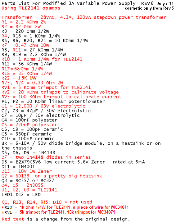
There are a few threads about this project. The latest BOM and schematic are many years old and have been posted hundreds of times in the threads. A few pcb designs have been shown. Recently a member organized these files and requested that a Moderator post them at the beginning of one of the threads but I don't think it happened. I fixed the project but never built it. If I built it then I would have posted it as a new project. I found it. Look at the reply from Peter K on August 15, 2014 in this thread.
-
Yes, most 10-turns trimpots have excellent quality. Yes, a wirewound resistor increases in value as it heats. Maybe yours is too small so it gets too hot? Maybe it is enclosed and gets hotter and hotter? Maybe it has poor quality?
-
The output transistors and the BD139 driver transistor get warm when they dissipate power. Power= x voltagecurrent. So they heat when the current is high and the output voltage is low (because then these transistors have a high voltage across them). If you set the voltage to 30V, set the current to 1.5A and have a 12 ohms load then the 30V across the 12 ohms would normally cause a current of 30V/12 ohms= 2.5A. but the current regulator causes the output voltage to drop to 1.5A x 12 ohms= 18V. Since your current drops after a while then maybe the current sense resistor R7 increases its value when it heats (wirewound?). Or maybe your current-setting pot changes its value? The photo of the circuit board is this modified project and the pcb was designed and built by Redwire.
-

Simple question about a schematic.
audioguru replied to abador's topic in Electronic Projects Design/Ideas
Hi Abador, I think we met on the other website forum. The datasheet tells you all about it. 1) In the low-cost circuit the Standby and Mute pins are connected together and are fed through a voltage divider with a slow delay capacitor C4. Vs is the supply voltage Vcc. 2) In the microprocessor circuit the Standby and Mute pins are fed through resistors and have slow delay capacitors and are fed 0V or +5V separately from the microprocessor. A negative supply called Vss is not shown anywhere in the datasheet because this IC is designed for using a positive supply and 0V ground. An input audio jack has left channel, right channel and ground terminals. Simply connect them to the amplifier circuit. The input ground is pin 9 of the IC. -
The wiring or the opamps are defective. Maybe you built the circuit on a solderless breadboard and its strips of contacts and connecting wires are picking up mains hum or causing high frequency oscillation. The maximum input offset voltage for a TL072 is listed on its datasheet as 10mV. The voltage gain of the first opamp is 1 so its output should be plus or minus 10mV or less. The voltage gain of the second opamp is a little less than 1.6 so its output should be plus or minus 32mV or less. Most opamps will have much less offset voltage. The voltage gain of the 741 opamp is 71 so the output of the second opamp is wrong at 3.74V/71= 53mV. Speaking 5cm from an electret mic produces about 20mV RMS which is 28mV peak. The input to the 741 opamp will be 28mV x 1.6= 45mV peak and its output will be 45mV x 71= 3.2V which will light a red LED but dimly light a blue or white LED. Maybe your voice does not produce low frequencies (are you a girl?).
-
We have discussed the 0-30V power supply project for at least 9 years and I fixed its many problems a few times. The original defective project is still in the Projects Section of this site and there are a few very long threads about this project in the forum. Recently Peter K organized all the fixes (I have not checked them yet) and are attached in my reply here. Yes. The fT is the frequency an opamp's gain has dropped to 1 and when its phase shift is pretty bad. I also have not calculated the values since I simply copies the original ones. 0-30V_PSU__Troubleshooting.pdf

-
Your mic might be defective. The datasheet does say it is an electret mic but I think it is. The polarity of its wires is not shown but I assume that red is signal and black is shield ground. Swap the wires to see if it works. If the unshielded mic wires are too long then they will pickup mains hum. LEDs 1 and 2 should blink: "1, 2 pause 1.2 pause" on and on where 1, 2 pause is one heartbeat. Nothing in the schematic will cause one LED to light steadily and the other LED not to light. Maybe you have C2 connected with backwards polarity? The output of the TL072 opamps should be 10mV (0.01VDC) or less. If the 741 opamp has its worst input offset voltage of 6mV then the gain of 71 times in this circuit will cause its output to be 0.4V which is not enough to light an LED. Measure and report the output voltages of the opamps with no signal.
-
I used my experience. There is a similar power supply output circuit on this site. The opamp and output transistor fT's are not known so the values must be calculated properly to match them so that the amplifier has enough phase margin to prevent oscillation.
-
It has a few serious problems, Kevin: 1) Its voltage gain is only 1 because the negative feedback is wrong. 2) Its slow output transistor will cause oscillation without compensation capacitors. 3) Its maximum output voltage is about 26V instead of 30V. 4) It will be destroyed if the output current is too high or is shorted because it is missing current limiting or regulation. Here most problems are fixed except it still has no current limiting:
-
The 28V transformer produces a peak voltage of 39.6V. If the maximum output current from your project is 2A then the transformer must produce 39.6V x 2A= 79.2VA. But the transformer is rated for 28V x 3A= 84VA so it will be very warm but be fine. 0.67 ohms is not a standard value, use 0.68 ohms for R7. Its max dissipation is 2 squared x 0.68 ohms= 2.72W. Use a 5W resistor. The unregulated loaded voltage will be 39.6V - 2V - 1V= 36.6V. If the output is shorted at 2A then the output transistor (s) must dissipate 36.6V x 2A= 73.2W which is a lot for a single 2N3055 transistor even if it has a big heatsink but it will be fine if a fan is added. Use two output transistors on a pretty big heatsink without a fan.
-
Since you do not understand the extremely simple schematic then maybe you should buy an amplifier that is already made. You were given 3 choices. Narrow down how much power, what supply voltage??
-
In your other thread the TDA7297 bridged stereo amplifier IC was recommended. Did you see its datasheet? Newark has them in stock. A lowpass filter does not boost the bass, instead it cuts the highs. A bass boost circuit is half of a simple bass-treble tone controls circuit. Adding a subwoofer needs a third amplifier for it, a highpass filter for both stereo channels and a lowpass filter for the input to the sub-woofer amplifier.
-
Hi Vakeiros, You can reduce the value of R7 to 0.33 ohms for a maximum output current of 4A but when the output voltage is low or is shorted then the driver and output transistors will get very hot. For a 5A circuit we recommend using 3 output transistors (each with a series emitter resistor), then they share the heat. With a 25V transformer you probably will not have an output as high as 30VDC when the current is 4A.
-
LM384N/NOPB-IC amplifier with heatsink
audioguru replied to a topic in Electronic Projects Design/Ideas
I am amazed that there are still a few of these old car radio amplifier ICs still available in North America. -
You are measuring the voltage drop across the resistance of the wires connected to your short circuit. Your voltage meter is connected to the output terminals of your project, not to the short circuit. Try connecting a very thick wire with a short length directly between the output terminals of your project. My very accurate ohm-meter measures its thick connecting wires to be 0.3 ohms when I press the probes together very hard. Then if there is 3A flowing, the wires will produce a voltage drop of 0.3 ohms x 3A= 0.9V.
-
Sorry, I cannot understand your broken English. Russian? Your youtube link does not work. Do svidaniya.
-
LM384N/NOPB-IC amplifier with heatsink
audioguru replied to a topic in Electronic Projects Design/Ideas
The TDA2009A dual amplifier is available inexpensively almost everywhere and can be bridged. But the datasheet is a nightmare, it shows the bridged circuit but says NOTHING about its supply voltage for it to have an output of 18W into 8 ohms at 1% distortion. I guess its supply voltage is 20V. -
LM384N/NOPB-IC amplifier with heatsink
audioguru replied to a topic in Electronic Projects Design/Ideas
The datasheet for an LM384 amplifier IC shows that with a 20V supply its output is about 3W into 8 ohms before clipping. It heats with about 2.5W so it will need a pretty good heatsink that is not available anymore. How will you cool it? The maximum 20V current is (3W + 2.5W)/20V= 275mA. Radio Shack online does not have an LM384. They have a low power (0.45W) LM386 instead. An LM1875 amplifier IC is available at Digikey and many other places (not at Radio Crap). It can be bolted to a modern finned heatsink. With a 16V supply its output is about 2.5W into 8 ohms and with a 60V supply its output is 32W. A modern amplifier IC (might not be made anymore, 10 years ago there were 76 amplifier ICs available made for car radios) uses two amplifiers in a bridge. Each amplifier drives each wire of a speaker out-of-phase so that the effective voltage is doubled which also doubles the current resulting in about 3.5 times more output power. Today many amplifier ICs are in tiny surface-mount packages and use class- D (PWM) so they do not get hot. -
Thanks, Peter. I did not organize the changes since I never built and tested this project, I simply added my opinion about how to fix its problems. The original project had many errors.
-
LM384N/NOPB-IC amplifier with heatsink
audioguru replied to a topic in Electronic Projects Design/Ideas
The LM384 is VERY old and needs the obsolete heatsink to survive. Use a newer amplifier IC. With the obsolete heatsink its output was 5.5W with horrible sounding 10% clipping distortion. Its output before clipping was about 4W which sounds only a little louder than a cheap clock radio. A modern LM3886 IC can be mounted on a real heatsink and produce 50W into 8 ohms at very low distortion. -
The MJ21194 has very powerful specs on its ON Semi datasheet. But yours has a tiny little chip inside and is marked Mexico and with the same date as the cheap ones sold by a Chinese company shown in Google Images. Why are American transistors made in Mexico sold cheaply in China?? Because they are fakes? The name Motorola Semi was changed to ON Semi in 1982 when all their transistors became marked "ON" instead of "M". Maybe counterfeiters don't know that. Here is an expert who discusses fake transistors: http://sound.westhost.com/fake/counterfeit-p1.htm
-
I have never bought any parts from ST Micro. They are Italian and I am Canadian.
-
Each contact can switch up to 5A so the total for all three contacts is 15A. We do not know the voltage the contacts will switch so we cannot calculate the power (voltage times current) that is switched to a load. EDIT: You are very confusing because your relay contacts are not connected to anything. Your 12V adapter is connected ONLY to the relay coil which has a low current of 75mA DC, not 5A.
-
Why are you connecting a 28VDC LED lamp to 220VAC? It will EXPLODE! LEDs need DC and they need their current limited by a series resistor or circuit. The relay is simply three on-off switches that all work at the same time. When it is turned on then the contacts are turned on. The power consumption of the relay coil is not 9mW, it is 12V x 75mA= 900mW. The LEDs are not in parallel. When the 220VAC is active then the bottom LED blows up. When the relay turns on then the top LED blows up.
-
Some fake transistors have some tin foil inside instead of a transistor chip. :( In Google I found your transistors being sold in China: