

HarryA
-
Posts
453 -
Joined
-
Last visited
-
Days Won
24
Content Type
Profiles
Forums
Events
Posts posted by HarryA
-
-
There is information here on Visual Servoing that maybe helpful; particularly the numerous references at the end of the article.
https://en.wikipedia.org/wiki/Visual_servoing
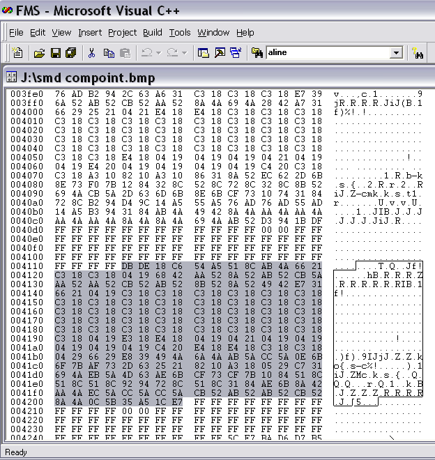
If you look at a bmp file of a smd image like this one (I could not find an image of the bottom of a smd).
You can see the white background as FF FF FF and one scan line across the component highlighted. So in theory one could find the four corners and calculated the rotation and any x y offset. In bmp files the image is inverted.
If you only need the rotation then only part of one edge would be required to calculate it I believe.
-
You may find some useful information here. If you need more help come back here.
https://github.com/openpnp/openpnp/wiki/Setup-and-Calibration%3A-Bottom-Camera-Setup
I worked for a company that made PnP and Through-hole machines but I only worked on the Through-hole machines.
-
what is the replacement for the d13005ed?
Perhaps the MJE13005G ? The data sheet is online.
The MJE13005G from China
see: https://www.ebay.com/itm/5PCS-X-UTC-MJE13005G-C-TM3-T-TO-251-I-PAK-NPN-Vceo-700V-Ic-4A-Transistors/333530195913? hash=item4da7f2e7c9:g:9MgAAOSwr9ReWXceThe D23005Ed 20 of them! "20 x D13005ED Transistor TO-220" from China.
also see for large list of similar transistors:
https://alltransistors.com/crsearch.php?at=Si&struct=NPN&pc=65&ucb=700&uce=400&ueb=9&ic=4&tj=150&ft=4&hfe=15&caps=TO220 -
If it is worth 21$ to you. You can always sell it on ebay when you are done with it 😉
https://www.amazon.com/Service-Technical-Information-Compact-Digital/dp/B00KV315WI
It's 29.99$ on ebay
-
If you open the unit up and find out what is wrong with it that will give you insight into what the problem is/was.
If the problem is on the AC input side it may well be, as you say, a spike from the power source.
-
I am confused by the circuit. If -v is grounded at connector CN1 then it is grounded at connector CN2 also. If so then capacitors C18,C19, C20, and C21 are grounded on both ends? Thus there would be no 1/2 voltage and +v would be at full voltage off the bridge rectifier?
I must be reading the schematic wrong.
-
the circuit below works in the LTspice simulator and as a prototype:
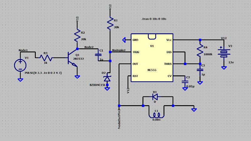
Traces from the simulator:
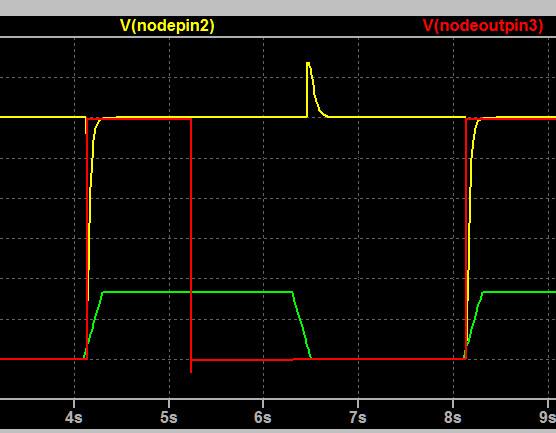
The green trace is the input from the sensor, the yellow trace is at pin 2, and the red trace is the output at pin 3. Note the positive going pulse when the input drops back to zero. That is why the Zener diode is required to limit it. Here it is a 15v Zener diode.
The output from prototype the circuit: Here I am using 9 volts as I only have 12 volt Zeners.
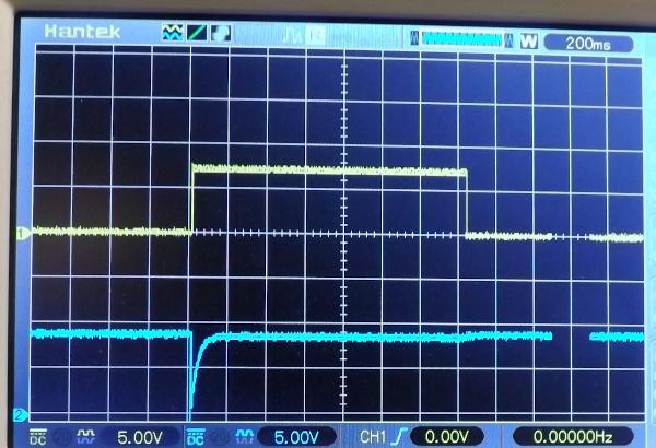
Here the blue trace is the trigger signal at pin 2 and the yellow trace is the output at pin 3 across a 150 ohm resistor for a relay load. The diode across the relay coil can be any general purpose diode like a 1N007 for example. The output is much wider then I would expect for R4 at 1Megohms and C3 at 1 microfarad. Expected 1 sec. not 1.4 There are numerous online calculators for calculating these values.
The values for the resistors are not critical except what you pick for R4:
- R1: 1000 to 1500 ohms
- R2; 20k to 30K "
- R3: 30K to 50K "
all work in the simulator.
-
The problem with the 555 timer is that it is not edge triggered and it is retriggerable. You would like a one-shot that is rising edge triggered. Retriggerible means as long as a moose stands in front of the PIR the 555 would output a pulse; having inverted the output with a transistor. Thus the relay would stay energized. That is okay if you want to make a movie of a moose but not good for one photo.
The 74121 is a nonretriggerable and is edge triggerable, that would be a better fit.
I will look at your circuit to see if it be used. I am thinking perhaps one could invert the PIR output with a transistor and discharge a capacitor to momentarily pull trigger pin 2 low.
What is the resistance of your relay if you already have one? One needs to know how much current it would draw.
-
That looks good. Good use of the capacitor. If you replaced the DPDT toggle switch with a relay powered of the supply on power failure would it switch to inverter automaticlly?
-
How fast is an MLX90614 IR temperature sensor?
https://www.electronics-lab.com/project/infrared-thermometer-arduino-mlx90614-temperature-sensor/
-
You need to create a pulse that goes from low to high and back again to low. Like the first pulse B:
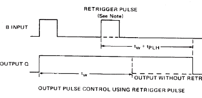
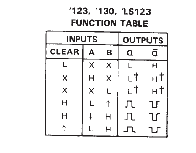
If you connect a resistor ( say 10k perhaps ) from the pulse in line to ground that will hold it low. Then connect your switch from the pulse in line to the Vcc the supply voltage. When you switch on the switch you create the rising edge like pulse B above. See line 4 below. When you open the switch you get the trailing edge of pulse B above. That is the transition for line 5 below. The function table may differ from this one for the one-shot you use. Remember if your switch is closed longer than the output pulse you create be sure to use a nonretriggerable chip. Analog makes chips of this type also: the LTC6993 family of one-shots.
.
-
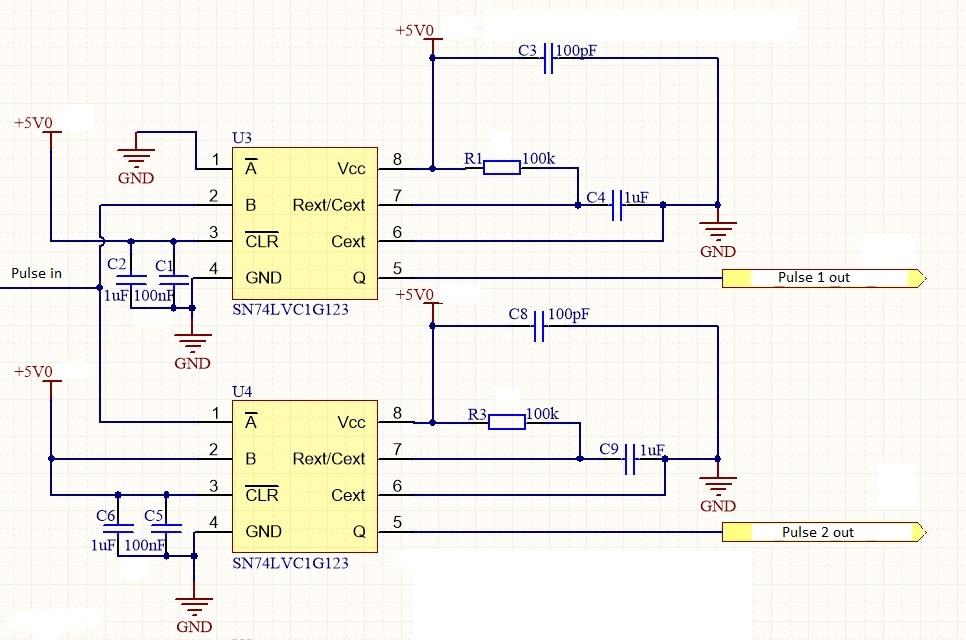
The circuit below uses edge triggering so you get an output on the rising edge and the falling edge of a pulse. The SN74LVCIG123 is a surface mount component but there is a throw hole chip; the 74123. The 74123 is a retriggerable monostable multivibrator (one shot). Retriggerable means that the output persist as long as the input is applied so if you switch closure is longer than the output pulse it still remains high.
The 74121 is a nonretriggerable version.
If you use a two position selector switch that would work; selecting ground or high. Else you may have to use retriggerable monostable to get a real pulse if you use a simple push button; as input to the circuit.
-
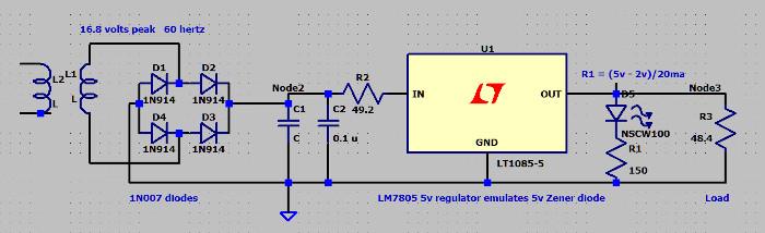
Doing a prototype of the circuit as shown below using a voltage regulator as I have no 5 volt Zeners:
I used 1N007 diodes and a LM7805 regulator. Transformer output 13.85 Vac 17.3 Vdc at the capacitors.
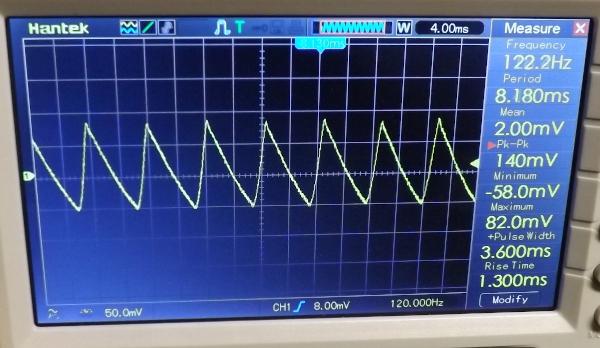
What I got for ripple voltage at the capacitor was:
- 536 mvpp with 1523 mfd cap. 140 mv ac with multimeter
- 288 mvpp with 3005 mfd cap 71 mv
- 200 mvpp with 4454 mfd cap. 48 mv
- 140 mvpp with 6050 mfd cap 36 mv
-
It looks similar to:
y[n]=0;
for(i=0; i<n; i++)
y[n] += x * b;
see:
http://pdfserv.maximintegrated.com/en/an/AN3386.pdf
What language is that? Never seen (long long) before. Perhaps like a double in C ?
-
The 12 volt transformer supplies a peak voltage of:
Vpeak = 12 * square root of 2 = 12 * 1.4 = 16.8
With 16.8 volts into the bridge we subtract 0.7 volts for each diode. As the current
passes through 2 diodes for 1.4 volts.
Vdc = 16.8 - 1.4 = 15.4 without a load.
The actual loaded voltage will be more likely around 14 volts as we will see later
with a capacitor and load. I am using 20ma LED here.
For the capacitor:
------------------
ripple voltage Vr:
Vr = (0.0024) * I/C = 100 mv
C = 0.0024 * I / Vr = 0.0024 * (0.120A / 0.10V) = 0.00288 F
0r: C = 2880 micro-farad
from Schertz and Monk "Practial Electronics for Inventors" section 11.6
For a Zener diode
------------------
Lets try the 5.1 volt 1N4733A. As 5.0 volt Zeners are hard to find.
For the 1N4733A Zener diode the value of Vz is 5.1V and Pz is 500 milliWatts
now with a Vdc (dc supply voltage) of 14V the value of R2 will be:
Rs = (Vdc - Vz)/Iz
Rs = (14 - 5.1)/Iz
Iz = Pz/Vz = 500mW / 5.1V = 98mA max.
Thus Rs = (14 - 5.1)/98ma = 90.8 ohms
Rs = 91 ohms (approx) 91 ohms is a standard.
The power/watts into R2 will be:
Pr2 = V^2/Rs = ((14 - 5.1)^2)/Rs = (8.9 * 8.9)/91 = 0.87 watts or 2 watts in practice.
So with a load of 120 ma the voltage drop across Rs:
Vrs = 91 * 0.12 = 10.92 volts ........oops! Looks we only have 14 - 10.92 = 3.08 for
the load and the Zener is out of business!
Lets try a 1 watt Zener and 5.1 volts:
Iz = 1.0 watt / 5.1 volts = 0.196 A or 196 ma.
Rs = (14 - 5.1)/ 0.196A = 45.4 ohms or 47 ohms standard
Voltage drop across Rs at full load: Vrs = 47 * 0.12 = 5.4 volts;
Or 14v - 5.4v = 8.6 volts for the Zener to chew on.
The power/watts into R2 will be:
Pr2 = V^2/Rs = ((14 - 5.1)^2)/Rs = (8.9 * 8.9)/47 = 1.685 watts or 2 watts or better in practice.
Next we can run this through the simulator and see what it looks like. (to be continued). -
Are you interesting in designing a circuit using mathematical equations or are you interested in building a power supply using proportional engineering (as a 6.3 volt filament transformer should work)? Proportional engineering is the way I build most things. Are you looking for help here?
-
Without a diagram of the circuit it is impossible to help you in spite of the good photographs.
It reminds me of the game tossing set mouse traps between players 🤪
-
Help NASA explore the moon and win up to 30,000$. See:
-
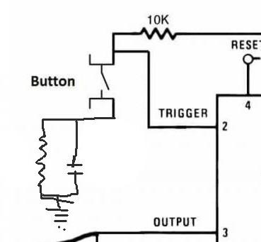
Two things from your circuit are the 20k ohm potentiometer and the 10k resistor at pin 2.
The potentiometer going from 0 to 20k ohms can produce a wide range of outputs in time/widths. So the RC circuit must charge above 4 volts fairly fast to accommodate the shortest output and while charging through the 10k resistor. A 1.0 ufd would require 20 ms, perhaps to slow. So trying a 0.1 ufd gives 400 microsecond which would seems fast enough(?).
To discharge the capacitor before the next switch closure the parallel resistor must set the voltage at pin 2 above the required 4 volts while the switch is closed. A 50k sets the the voltage at: 50K/(50k+10K) * 12volts or 10 volts a bit higher then necessary. A 10k resistor would set the voltage at 10k/(10k+10K) * 12 volts or 6 volts which would be adequate. Discharging from 6 volts to 4 volts in 2 ms after the switch is opened.
-
What you want to know is will the capacitor charge to above 1/3 of Vcc within the period of the 555 pulse; thus it will not get re-fired.
Using:
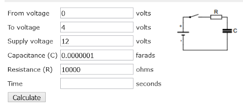
You get 405 microseconds, See:
http://mustcalculate.com/electronics/capacitorchargeanddischarge.php
And will discharge to 4 volts from 12 volts through the 50k resistor in 5.6milliseconds.
-
I am lazy and use one of the numerous online calculators like:
-
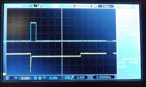
In the photo the yellow trace is pin 2 (trigger) and the blue trace is pin 3 (output). Starting on the left pin 2 is at the Vcc voltage of 12 volts (0 is at the bottom of the screen) . Pin 3 is at 0 volts. On switch closure pin 2 drops to near 0. And pin 3 rises to near 12 volts. The switch is held on until the later part of the trace on the right most side of the screen.
-
Try putting a resistor and capacitor in parallel after the switch. The capacitor will pull pin 2 down until it charges through the upper 10k resistor. The resistor in parallel with the capacitor will discharge the capacitor during the period the switch is open.
Do you need help with the calculations? As a quick test make the new resistor 50k and the capacitor perhaps 0.1ufd - I am just guessing. You want the capacitor to discharge before the output ends.
-

Introduction to Non-Inverting and Inverting Amplifiers Basics
in Electronic Projects Design/Ideas
Posted
Wikipedia has a well written article on operational amplifier applications.
see: https://en.wikipedia.org/wiki/Operational_amplifier_applications#Non-inverting_amplifier