HarryA
-
Posts
451 -
Joined
-
Last visited
-
Days Won
23
Content Type
Profiles
Forums
Events
Everything posted by HarryA
-

Design real time temperature monitoring
HarryA replied to electrical211's topic in Electronic Projects Design/Ideas
I do not know the PIC micro-controller so I can not help you directly. But there are videos on youtube that maybe helpful. for example: https://www.youtube.com/watch?v=yreD5sj-i80 Also for the basic calculations see: https://www.instructables.com/id/NTC-Temperature-Sensor-With-Arduino/ Good luck with your project. -
5S3P Series parallel reverse polarity protection ?
HarryA replied to Bka's topic in Spice Simulation - PCB design
Yes, you would want the diode across the cell not in series thus they would only conduct on reversed voltage. Your cells are connected in parallel due to the interconnectors thus I see no way to monitor the voltage of individual cells. -
5S3P Series parallel reverse polarity protection ?
HarryA replied to Bka's topic in Spice Simulation - PCB design
Are the leads from R13, R14, & R15 shorted by the interconnections between B10, B11, & B12 ? As the fuses interconnect them. I do not understand why, in say laptop batteries, the cells are interconnected that way. Perhaps for balance charging? It is common practice to put a diode around each cell in reverse connection for protection. -
You can get a 120 volt to 48 volt transformer for about 15$ off Ebay. That still leaves you with 60 hertz which would be expensive to converter down in frequency. Perhaps 60 hertz would work? I used a pocket am/fm radio for a signal device; just opened the lead to the battery for external connections. You can get one for 10$.
-
5S3P Series parallel reverse polarity protection ?
HarryA replied to Bka's topic in Spice Simulation - PCB design
See "PCB Protection Board For 18650 Li-ion Lithium Battery Cell " https://www.ebay.com/itm/2S-3S-4S-6S-BMS-PCB-Protection-Board-For-18650-Li-ion-Lithium-Battery-Cell-US/283479999258?ssPageName=STRK%3AMEBIDX%3AIT&var=584554774361&_trksid=p2057872.m2749.l2649 Also see "Build a 2S Li-ion Battery Pack with Protection" https://www.youtube.com/watch?v=VwIYAiDlMz4 -
5S3P Series parallel reverse polarity protection ?
HarryA replied to Bka's topic in Spice Simulation - PCB design
Do you need reverse polarity protection only when in use? As I take the batteries out of my camera to charge them. Only when you are charging the batteries? Or both? -
What type? Voltage Amplifiers: Power Amplifiers: Class A, B, AB, & C Audio Frequency Amplifiers (A.F. Amplifiers): Intermediate Frequency Amplifiers (I.F. Amplifiers): Radio Frequency Amplifiers (R.F. Amplifiers): Direct Coupled Amplifiers (DC Amplifiers): Ultrasonic Amplifiers: Wideband Amplifiers: Video Amplifiers: Buffer Amplifiers: Operational Amplifiers:
-
String lights in resin lamp
HarryA replied to Blue Tarheel's topic in Electronic Projects Design/Ideas
If you could make a slight indentation or groove at the wires with a Dremel like power tool perhaps you could fill it with conductive epoxy? Silver based epoxy is best but expensive. For insight into conductive epoxies see: https://www.permabond.com/2016/07/26/electrically-conductive-adhesives/ -
There are dc electronic dummy loads reviewed on youtube.com if that is helpful. They run 200v, 20A, and 180watts. For example see: https://www.youtube.com/watch?v=bx74sNFQvwc
-
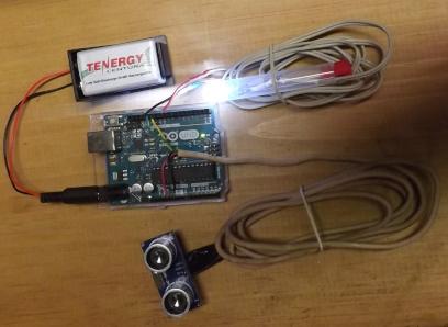
An experimental blind spot monitoring (BSM) for an automobile. One can attach the sonic sensor on the rear section of the automobile. I mounted mine on the flap door that covers the gasoline cap. I used a length of good duct tape that wrap around the inside of the flap door also. I ran a length of 4 wire telephone cable from the sensor through the backdoor gap into the backseat. Then a length of 2 conductor wire from the Arduino Uno to the dash for a white LED. The LED has an 68 ohm resistor in series with it. The LED and resistor lives in the plastic tube For the Arduino Unio one can control the LED blinking without using the Delay() by: int iLEDstate = LOW; // used to set the LED state const long lInterval = 1000; // interval at which to blink (milliseconds) unsigned long lPreviousMillis = 0; // will store last time LED was updated int iDashLED = 10; // LED on/off pin pinMode(iDashLED, OUTPUT); //only distances more than 3 ft and less than 12 ft if(lInches > 36 && lInches < 144 ) { Dash_LED_Blink(); //blink the LED } else if (iLEDstate == HIGH) { iLEDstate == LOW; digitalWrite(iDashLED, iLEDstate); //make sure LED is off } void Dash_LED_Blink() { // check to see if it's time to blink the LED unsigned long lCurrentMillis = millis(); if (lCurrentMillis - lPreviousMillis >= lInterval) { // save the last time the LED blinked lPreviousMillis = lCurrentMillis; // if the LED is off turn it on and vice-versa if (iLEDstate == LOW) { iLEDstate = HIGH; } else { iLEDstate = LOW; } // set the LED with the iLEDstate digitalWrite(iDashLED, iLEDstate); } }
-
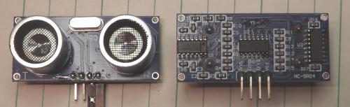
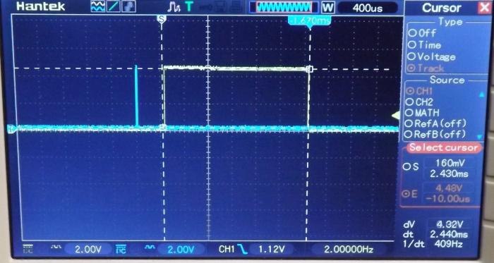
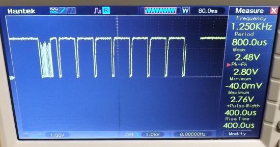
In the photography is the "Ultrasonic HC-SR04 distance measuring transducer sensor". "HC-SR04 consists of ultrasonic transmitter, receiver, and control circuit. When triggered it sends out a series of 40KHz ultrasonic pulses and receives echo from an object. Power supply: 5V DC; quiescent current: less than 2mA; effectual angle: less than 15°; distance: 2cm - 500cm." The sensor is 1.75 inches/ 4.45 cm by 0.75 inches/ 1.9 cm. The IC on the bottom left is an LM324 quad op amp. The two on the right are not marked. // The sensor is triggered by a HIGH pulse of 10 or more microseconds. Give a short LOW pulse beforehand to ensure a clean HIGH pulse: digitalWrite(iTrigPin, LOW); //pin 12 Out delayMicroseconds(5); digitalWrite(iTrigPin, HIGH); delayMicroseconds(12); digitalWrite(iTrigPin, LOW); // Read the signal from the sensor: a HIGH pulse whose duration is the time (in microseconds) from the sending of the ping to the reception of its echo off of an object. pinMode(iEchoPin, INPUT); //pin 13 In lDuration = pulseIn(iEchoPin, HIGH); The photography shows the trigger pulse in blue and the signal from the sensor in yellow bracketed by the white cursors. In the lower right is the width of the pulse: 24.4 ms from a object at 16 inches/ 40.6 cm from the sensor. // Convert the time into a distance - long way for clarity lCM = (lDuration/2) / 29.1; // Divide by 29.1 or multiply by 0.0343 lInches = (lDuration/2) / 74; // Divide by 74 or multiply by 0.0135 So for 2440 us/2 = 1220/74 = 16.48 inches or 1220/29.1 = 41.9 cm
-
White LEDs are typically 3.6 volts and 20ma each. So for the 6 LEDs you would need in the order of 21.6 volts and 20ma. You could try two 9 volt batteries as a test. You can connect two batteries head to head with the + to - connectors. For insight on testing LED strips with batteries see; https://www.youtube.com/watch?v=4pK6o2DMLWQ
-
Also see: https://www.fixya.com/support/t8108170-click_multi_functional_rechargeable for more discussions on the rechargeable torch..
-
Can you connect a 240v buzzer to the relay and get what you need? I don't know the circuit so I can not help much. Perhaps someone more knowledgeable will come along. I would think that the lead from the mains/transformer to the relay would be from the lead that has the fuse and power switch on it. The URL is here: https://www.electronics-lab.com/project/darkroom-timer-v2-0a-for-pcb-exposure-box/ What does this circuit do that a 60 minute egg timer could not do?
-
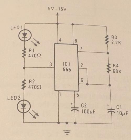
The LEDs flash alternating. The flash rate is determined by C1 and R4. There are online calculators for determining these values. Just supply power for the hazard signals. Supplying power and disabling one or the other LED for the turn signal. Redraw the circuit with circuitlab and add a DPDT switch with center off perhaps for the turn signal.
-
You should draw the fuse F1 as a blown fuse, you have a short circuit by the wire/conductor on the right. That was a test right? To see if anyone really looked at it 😉 Isn't the 7805 a voltage regulator? Not a flasher? What are the" flashers" connected to? Shouldn't they connect to the anode leads of the LEDs rather then the LEDs connecting to the Low Beam Terminal? What happens when the left and right flashers and the hazard flashers are on at the same time? Maybe okay. Could the DPDT switch be replaced with a SPST switch? Also on your SPDT there is no off position. Otherwise the schematic looks better than my poorly hand drawn schematics.
-
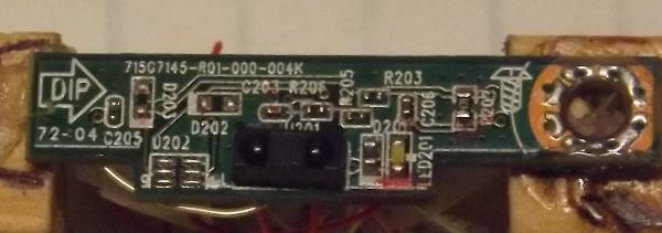
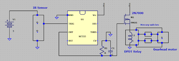
In the photography is the remote control receiver module from a VIZIO television. At the lower center is IR sensor and to the right of the sensor marked by red is the power on white LED. This photography shows the output from the module when a remote control button is pressed and held. The burst of pulses identifies which button was pressed. Following this burst are the Keep Alive Pulses (KAP) - my designation. As long as a button is held down this train of pulses are produced. Used for example when changing the audio volume. The KAP are 10.5ms wide and spaced every 107ms. A simplified overview of a circuit I used to control a small gearhead motor. The KAP are feed to a 555 timer (as a monostable) that produce larger positive pulses. A leaky capacitor integrates the pulses that drive a transistor to power a DPDT relay. The relay's NC contacts powers the motor CCW until a mercury switch switches the power off. When a signal is received the relay switches the NO contact to closed, then the motor rotates CW until power is switched off by a second mercury switch. When the remote button is released the relay transitions and the motor rotates back CCW to its starting position. The mercury switches are mounted 90 degrees apart on a disk being rotated by the motor.
-
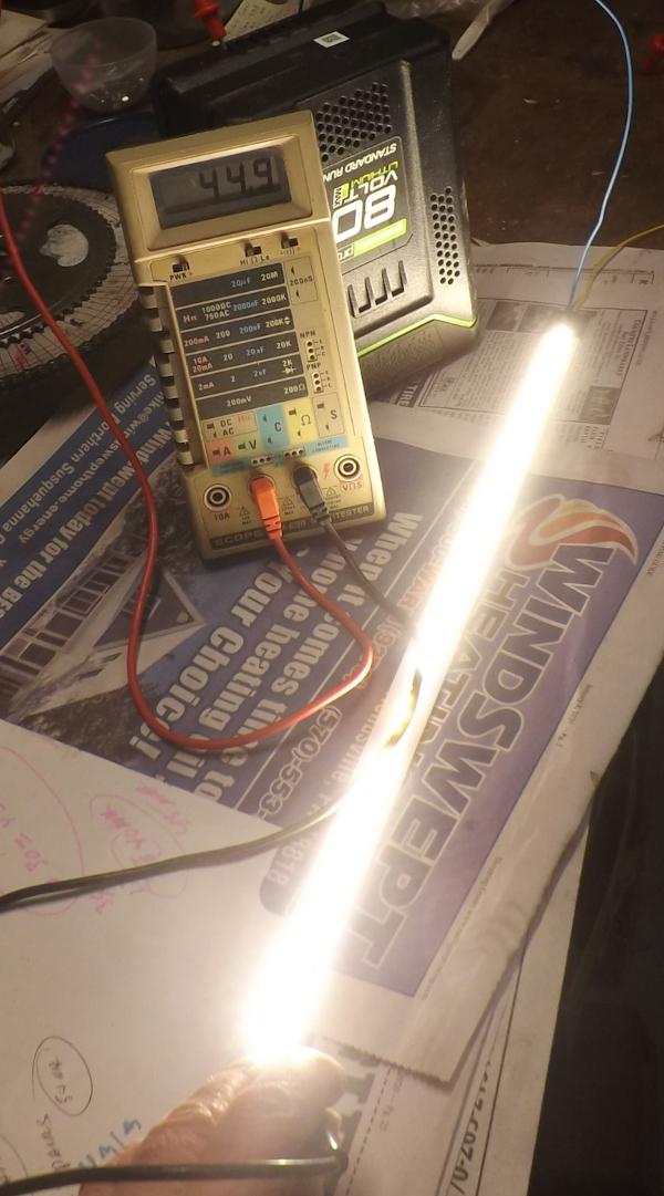
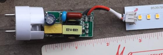
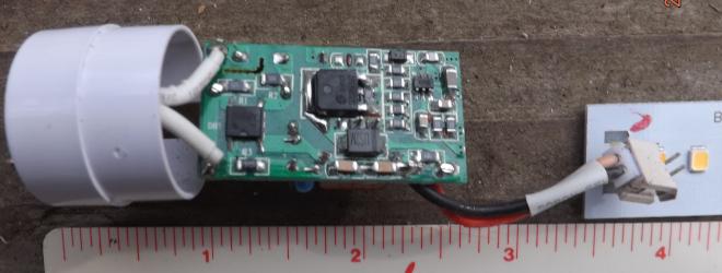
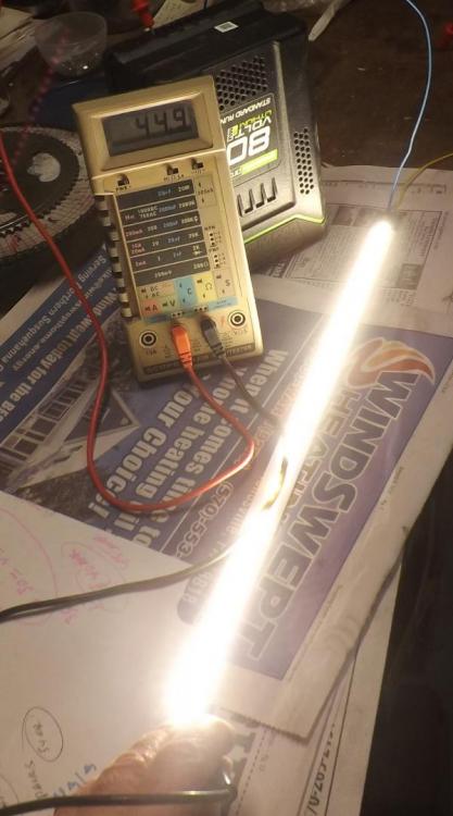
The photographs show the working end of a 24 inch LED tube light. This type of light only requires connections to one end. No ballast is required for this light. The light yellow device at the lower right is the transformer. Next to it is a yellow capacitor. On the bottom the larger three leaded component is labelled: SDL2N65UZ. There are 72 LEDs in the strip. The LEDs are arranged in pairs in parallel so there are 36 pairs in each strip. An 82 volt battery will light the first 30 pairs with a current of 44.9 milliamperes. White LEDs are rated 3.6 volts at 20 milliamperes.


-
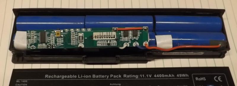
For those who have not peeked in to a laptop battery the photo shows the interior of one. The battery is made up of 6 lithium ion cells of 3.7 voltages each in three pairs. Connected to each pair are connections for balanced charging. This battery does not have thermistors for monitoring temperature during charging as some do. At the upper left is a larger SMD IC that is most likely the processor or brains of the battery. To the right of the IC is a tan rectangle with a red dot on it. This is a switch that can be press through the case. It is used to display the status of the battery by the 5 LEDs just to the right of the switch at the upper edge of the PCB. There are 2 more SMD ICs at the upper right.
-
For you folks that have not worked on a gas range /kitchen cook stove. In the photo the igniter at the top draws current through the gas valve below. The igniter draws current slowly at first as it heats up to typically 3.5 amperes. Only then does the heater (white windings) in the valve heat the bimetallic strip. It then rises upward uncovering the output port normally covered by the silicone round pad on the right. Thus the gas valve can only allow gas to flow into the burner if the igniter is functioning properly.
-
Help request about an optimum switching design
HarryA replied to kaimdaim's topic in Electronic Projects Design/Ideas
There are only 6 unique numbers in each column above. If you used 4 rotary switches with one wafer each that would only require 6 * 4 = 24 contacts. A 6 position switch with one wafer:
-
Help request about an optimum switching design
HarryA replied to kaimdaim's topic in Electronic Projects Design/Ideas
I do not understand enough what you are doing to be helpful. Can you say, as a model, each electrode is like a wire of different metal (like copper, zinc, iron, etc) placed in an solution such that each creates a different electromotive force (emf) or voltage. Each wire/electrode has a higher emf going from 1 to 9 perhaps? Like wire 1 has 0.1 mv emf, wire 2 has 0.15 mv emf, and so on. -
Help request about an optimum switching design
HarryA replied to kaimdaim's topic in Electronic Projects Design/Ideas
You need to define " driven electrodes ". Are they two leaded devices? Can they share a common ground? Do you have a set of relays in mind? If so can you use solid state relays? -
Looking for a good design for a PIC based VU Meter
HarryA replied to tvguy24's topic in Electronic Projects Design/Ideas
Sorry I can not help you with the PIC; I use the Arduino myself. But there is a lengthy discussion of 4 pages related to the PIC and VU meters here: https://groupdiy.com/index.php?topic=43594.0