

HarryA
-
Posts
453 -
Joined
-
Last visited
-
Days Won
24
Content Type
Profiles
Forums
Events
Posts posted by HarryA
-
-
I used: bluetooth camera for iphone
also see: https://techpp.com/2013/04/17/bluetooth-cameras-connect-smartphone/
-
Perhaps? To big?
" This Fujifilm FinePix digital camera has Bluetooth connectivity for wireless media transfer. "
-
If you do not need SMD perhaps "The LT138A/LT338A (LM138/LM338) series of adjustable regulators provide 5A output current over an output voltage range of 1.2V to 32V."
The LM338 is about 1$ each on ebay.
-
Search on ebay for "personal alarm switch" most do not have a switch just a pin you pull out.
I used one to find the blockage in a drain pipe. They are LOUD!
-
Power Strip with USB, Surge Protector Smart 3 Outlet and 4 USB Port Charger with 5ft Extension Power Cord 1250W 100-240V
I worked with a power supply that was 900 amperes and 8 volts; this would not work for that
")
-
This maybe helpful: How to make an IR blaster:
https://www.instructables.com/id/How-to-Make-an-IR-Blaster/
This is an old question but it maybe helpful to someone in the future.
-
audioguru is correct. But if you are interested in cell phones you may find this site helpful:
https://www.instructables.com/id/Make-your-own-cellphone-from-scratch/
-
I would use an arduino microcomputer with an arduino display shield for the display.
The best microcomputers are about 22$ down to a few dollars for the ones from China.
The arduino display shields are around 10$ or so. The Utlransonic distance measuring transducer senors
are less than 10$; they detect if you are in your seat or not.
https://www.amazon.com/s/ref=nb_sb_noss_1?url=search-alias%3Daps&field-keywords=arduino+uno
-
One can go from 50hz ac to 12 vdc via battery charger then from 12 vdc battery to 60hz 120v via a dc to ac converter.
see:
-
using "the GIMP"
-
Hello,
I would think few of us would know anything about mig welders. I gather you want to hot switch the current from the mains
to the welder. What current does your welder draw would be a start. You may need a high current relay to do the switching.
It's rated "AC contract rating - relay: 25 amperes at 240 volts ac." You need a relay rated higher than it draws off the mains because of the inductive load - I gather the mig welders have a transformer at the input like an arc welder?
-
How about 3 terminal adjustable voltage regulators?
60 volts max and 1.5 amperes. Poke around at Mouser for higher current ones also. There are filters on their site that are helpful.
-
Your " unknown phone " is unknown to us also. One photo is worth a thousand words, two photos are worth two thousand words, etc
")
-
6 hours ago, anonymous said:
carry more than 20kg object
You need to define this so someone can help you.
-
The power required by the charger would be in the order of: 120 * 0.3 = 36 watts.
The
220/240 To 110/120 Volt European Socket Power Converter Step Down Transformer
off ebay.com are rated 100 watts and not expensive. Order one directly from China; it's just up the big pond from you
-
I enlarged the image off the Amazon.com but could not read it

...but ebay.com has a readable image
")
120v @60hz 300ma
-
" which one is right? " What two are you comparing?
-
This unit will work stand alone (with out a UNO) and has wifi>
Read the Q/A section.
-
If you search on amazon.com for "arduino wearables" you will find a number of devices.
There are also a number of books on the subject.
-
I gather if you want 1.8 volts out you buy the LP3853ET-1.8/NOPB
and if you want say 2.5 volts you buy the the LP3853ET-2.5/NOPB chip
and so forth. They must define the input voltages for each somewhere?What do you mean by "Can I use LP3856 here ?" ? What is your application?
-
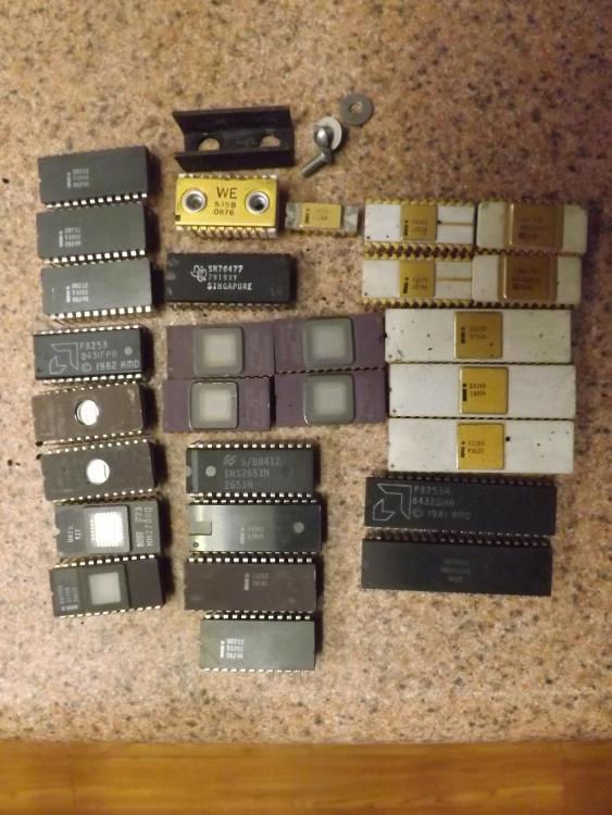
Free to good home for 5$ shipping and handling.
Save them from the land fill! Some are old enough to be your parents!
Antediluvian? You will have to look it up.
-
"50Pcs NPN Transistor TO-92 2N2222A 2N2222 Brand New Practical High Quality" (Ebay)
Does "Practical High Quality" mean hfe's of almost 100

-
Hello, I will look at what maybe needed. I am thinking a pair of 555 timers (better but more expensive are the mc1455p timer clock chips). One for the 5 second delay which triggers the second one for the 1 minute on delay. The second one feeds a divide by 5 counter chip for the 5 minutes.
For the photo cell perhaps a photo transistor. I just finished a circuit that uses a infrared television sensor to trigger a 555 chip via the television remote.
You may want a breadboard and a few jumper leads. Also if you do not have any electronics instruments look for a simple logic probe circuit on the internet; it will use a led as an indicator that the timers are pulsing. It can be fabricated on one end of the breadboard.
Then the devil is in the details. Perhaps we can con audioguru into helping with them; he is quite knowable.
On second thought one could build LEDs into the circuit so no logic probe would be necessary.
-


Help interpreting Circuit schema please...
in Electronic Projects Design/Ideas
Posted
At the lower left the component would be a 1500/1k5 resistor like the one at the lower right.
The LEDs indicate which coil/output is active. At the upper right the symbol looks like a ground off the signal generator.
The LEDs are represented by the white dots on the front panel above the words OUT perhaps?
P1 and P2 look odd; they have the potential of shorting the inputs. At P2 with the wiper all the way down the input would be shorted circuited.