help with IR2110 chips

Alec_t

Jul 7, 2015
3,817
Joined
Jul 7, 2015
Messages
3,817
what about my 7 ohm coil that produces 14 volt ac and 28v dc
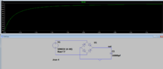
At what wheel rotation rate? Are we talking real life or simulation? Is that 14V peak or RMS? How is the coil producing DC?
I don't get what you mean by this?
Your fan (the inverter load) needs 15W of power to run at its rated speed.
No inverter is 100% efficient; 85% is more typical. So the needed input power to an 85% efficient inverter would be 15W x 100%/85% = 17.6W.
is it possible to add the outputs of the coils?
If you put in-phase coils in series then their output voltages will add; but so will their impedances, hence no current increase. If you put them in parallel then their currents will add but their voltages won't. The problem is that you need a power increase.
 
Last edited:

Maglatron

Jul 12, 2023
2,025
Joined
Jul 12, 2023
Messages
2,025
600 rpm real life
If you put in-phase coils in series then their output voltages will add; but so will their impedances, hence no current increase. If you put them in parallel then their currents will add but their voltages won't.
so no power gain?
the 28 volts is with the 7 ohm coil output through the rectifier that is still in the configuration I had it before in the image below
1707046557869.png
 
Last edited:

Maglatron

Jul 12, 2023
2,025
Joined
Jul 12, 2023
Messages
2,025
this is not a good reflection of what is happening in real life because in real life the DCvolts come to 28volt
 

Maglatron

Jul 12, 2023
2,025
Joined
Jul 12, 2023
Messages
2,025
so the simulation does not reflect whats going on, the voltage reaches 28volt on the meter for the 40Hz I did 600 / 60 = 10 and the * by the number of north poles (on one side), 4, = 40Hz, can you figure out the anomoly ?
 

Attachments

  • 1707047500976.png
    1707047500976.png
    78 KB · Views: 2
Last edited:

Maglatron

Jul 12, 2023
2,025
Joined
Jul 12, 2023
Messages
2,025
Your fan (the inverter load) needs 15W of power to run at its rated speed.
No inverter is 100% efficient; 85% is more typical. So the needed input power to an 85% efficient inverter would be 15W x 100%/85% = 17.6W
so why does the average power dissipation = 3.4watt? and not 18watt
 

Maglatron

Jul 12, 2023
2,025
Joined
Jul 12, 2023
Messages
2,025
If you put in-phase coils in series then their output voltages will add; but so will their impedances, hence no current increase. If you put them in parallel then their currents will add but their voltages won't. The problem is that you need a power increase.
wait using two coils must increase power because there are two of them!! rather than one
 

Alec_t

Jul 7, 2015
3,817
Joined
Jul 7, 2015
Messages
3,817
so why does the average power dissipation = 3.4watt? and not 18watt
Because a lot of voltage is dropped across the internal resistance of the coils, so power is wasted in heating up the coils.
the 28 volts is with the 7 ohm coil output through the rectifier that is still in the configuration I had it before in the image below
That is not the same configuration as I suggested originally. You have connected both terminals of V1 to the diodes.
so no power gain?
There is power gain, but not enough.
so the simulation does not reflect whats going on
You are not using the voltage-doubling arrangement I suggested originally.

Edit:
The post #448 arrangement doesn't provide voltage doubling, but would provide voltage addition if diodes D3 and D4 were removed.
However, because coil pairs 1 and 2 are not in phase their voltages partly cancel during parts of the wheel cycle.
 
Last edited:

Maglatron

Jul 12, 2023
2,025
Joined
Jul 12, 2023
Messages
2,025
no I didn't understand it properly but this is the measurement of one coil, can you post again how you suggested please I'm getting confused, or tell me which post number it was, thanks
 
Last edited:

Maglatron

Jul 12, 2023
2,025
Joined
Jul 12, 2023
Messages
2,025
from what I understood the rotary generator that you modelled was to half the resistance and double the current
You are not using the voltage-doubling arrangement I suggested.
or am I missing something, I only half understand whats going on in that spice model winding another coil today and am going to fit it, then we have two coils to work with that are identical and in phase
 

Alec_t

Jul 7, 2015
3,817
Joined
Jul 7, 2015
Messages
3,817
Yes, that's what I meant for voltage addition/doubling. But remove R1, since V1 and V2 include series resistance.
Your circuit assumes V1 and V2 coil voltages are in phase, whereas my post #448 one has coil pairs with a phase shift.
 
Last edited:

Alec_t

Jul 7, 2015
3,817
Joined
Jul 7, 2015
Messages
3,817
Just running some numbers:
If the max voltage from your 7 Ohm coil is 14V and we assume its waveform is sinusoidal then its RMS voltage is 14 x root 2, = ~10V.
The maximum power it can deliver would be to a 7 Ohm load, so the current would be 10V/(7+7) Ohms = 0.714A, the voltage across the load would be 5V, and the power to the load would be 5V x 0.714A = 3.6W.
So to provide 18W for a fan it looks like you would somehow need to combine the power outputs of 18/3.6 = 5 coils (at least) with a similar output.
You might be able to get a higher per coil output with a more efficient magnetic circuit, e.g. by the addition of back-iron for the coils to minimise magnetic reluctance, but this would mean a major alteration to your generator.
 
Last edited:

Maglatron

Jul 12, 2023
2,025
Joined
Jul 12, 2023
Messages
2,025
so if I get 6 on then I'll be safe and also do you think I should mitigate the shift in phase? I'll be using 10 magnets
 

Maglatron

Jul 12, 2023
2,025
Joined
Jul 12, 2023
Messages
2,025
so I'm buying more of the copper wire and they don't have any 0.7mm they do have 0.724 and 0.574 what would you get?
 

bertus

Moderator
Nov 8, 2019
3,837
Joined
Nov 8, 2019
Messages
3,837
Hello,

Thinner wire would have a higher resistance.

Bertus
 

Maglatron

Jul 12, 2023
2,025
Joined
Jul 12, 2023
Messages
2,025
they dont have the same ones in stock that I bought last time!
 
Top