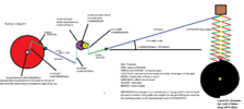
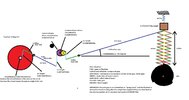
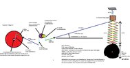
I want to know all of the maths concerning this scissor mechanism!

Maglatron

Jul 12, 2023
2,025
Joined
Jul 12, 2023
Messages
2,025
yes drop to minimum
Without knowing what is supposed to happen after 1.26m vertical movement its hard to advise on the cam profile. For example, if the cam suddenly stops, the load (and cam-follower) will carry on moving up until slowed to a halt by gravity and friction. Is that the intention? Or is the cam supposed to control descent too?
Why does your cam now have four lobes? Is the load supposed to drop down to minimum after each maximum? If so, it can't do that instantly.
did you read the pdf??
 

Maglatron

Jul 12, 2023
2,025
Joined
Jul 12, 2023
Messages
2,025
so I think I've settled on the design I'm going to have 3 lobes and it will take 0.25sec to lift the load, 3x if turning 2pi rad/sec
Without knowing what is supposed to happen after 1.26m vertical movement its hard to advise on the cam profile. For example, if the cam suddenly stops, the load (and cam-follower) will carry on moving up until slowed to a halt by gravity and friction. Is that the intention? Or is the cam supposed to control descent too?
Why does your cam now have four lobes? Is the load supposed to drop down to minimum after each maximum? If so, it can't do that instantly.
 

Attachments

  • 3lobe.png
    3lobe.png
    11.8 KB · Views: 0
Last edited:

Maglatron

Jul 12, 2023
2,025
Joined
Jul 12, 2023
Messages
2,025
Without knowing what is supposed to happen after 1.26m vertical movement its hard to advise on the cam profile. For example, if the cam suddenly stops, the load (and cam-follower) will carry on moving up until slowed to a halt by gravity and friction. Is that the intention? Or is the cam supposed to control descent too?
Why does your cam now have four lobes? Is the load supposed to drop down to minimum after each maximum? If so, it can't do that instantly.
the scissor lifts a weight of 175g the cam turns clockwise without stopping it lifts the weight up and drops down again when the lobes go past each time
 

Alec_t

Jul 7, 2015
3,817
Joined
Jul 7, 2015
Messages
3,817
If the load has a constant upward acceleration for the whole 1.26m of its travel, it won't stop at 1.26m if you are relying solely on gravity to cause it to descend. Will that be an issue?
 

Maglatron

Jul 12, 2023
2,025
Joined
Jul 12, 2023
Messages
2,025
not at all! infact that would be good but why would it continue up and for how much further would it move when gravity takes over and the edge of the cam drops off at the end of the lobe I see this like accelerating a tennis ball up wardsat a certain accelerate the ball would leave the hand also the weight of the lever which I have not accounted for
 

Maglatron

Jul 12, 2023
2,025
Joined
Jul 12, 2023
Messages
2,025
infact what I would do is put in a spring above the weight to bounce it back downwards like the ones that are at the end of a train track to make sure it doesn't go over 1.265m
 

Maglatron

Jul 12, 2023
2,025
Joined
Jul 12, 2023
Messages
2,025
modified project picture
 

Attachments

  • project labled.jpg
    project labled.jpg
    167.9 KB · Views: 6

Maglatron

Jul 12, 2023
2,025
Joined
Jul 12, 2023
Messages
2,025
The weight through the lever/ gear system has to accelerate against the inertia of the flywheel so it wouldn't be freefall if the flywheel is spun by the dropping weight through levers and gears and the initial rotational speed of the flywheel is 12pi rad/s 6 rotations/second or 360RPM and its inertia is 10.8kgm^2 and the acceleration is 0.05 rad/s^2 of the flywheel how to find the time the weight falls a distance of 1.26m and what will be the speed of the flywheel after the drop of the weight
this is important to me, thanks
 
Last edited:

Maglatron

Jul 12, 2023
2,025
Joined
Jul 12, 2023
Messages
2,025
anyone?? so put a couple more parameters on the image for visual understanding for the cam
 

Attachments

  • project labled.jpg
    project labled.jpg
    172.3 KB · Views: 2
Last edited:

Maglatron

Jul 12, 2023
2,025
Joined
Jul 12, 2023
Messages
2,025
so imagine this: you're peddling down hill in first gear the bike gets too fast for your legs to keep up, its like this how fast can the wheel be going before its at the speed when the weight drops and it's no longer adding to the wheel because it requires the weight to drop faster than gravity pulls it down? for example 4pi rad/s, 6pi rad/s, 8pi rad/s and for the given cam the 0.9m diameter with the 3 lobes how do you work out the slope of the circular ramps it goes 2pi rad/s?
 
Last edited:

Alec_t

Jul 7, 2015
3,817
Joined
Jul 7, 2015
Messages
3,817
Adding the spring above the load, to limit the upward movement , will result in the load's initial downward acceleration having a component which depends on the spring's unknown free length and compressibility. The flywheel's inertia, via the gearing, friction and gravity are the other components.
The weight and rotational inertia of the scissor mechanism itself, not considered yet, need to be taken into account in acceleration and deceleration calculations.
The maths is now above my pay grade; perhaps someone else would be willing to wade in.
I hope you can see by now why I objected to nine decimal places in your calculations :) .
 

Maglatron

Jul 12, 2023
2,025
Joined
Jul 12, 2023
Messages
2,025
hmm just need to find the slopes first of the cam if you can shed any light on that, one step at a time! so I worked out that the wheight drops as 0.5068m/s free fall and that it takes 0.4995sec for the weight to drop if the wheel starts at 4pi rad/s so I would only 2 lobes on the cam rotating at 2pi rad/s if you can help me with the slopes as one last thing I'd be highly greatfull, thanks
 

Attachments

  • proggress.png
    proggress.png
    297.8 KB · Views: 1
Last edited:

Maglatron

Jul 12, 2023
2,025
Joined
Jul 12, 2023
Messages
2,025
I'd love for someone "to wade in" anyone up for it??? I need to find the slopes of this cam the max diameter is 0.9m and the drops off the lobes is 0.126m if you could provide a method for this it would be very nice, thanks Mr Alec_t please?
 

Attachments

  • 2lobe.png
    2lobe.png
    9.6 KB · Views: 1
Last edited:

Maglatron

Jul 12, 2023
2,025
Joined
Jul 12, 2023
Messages
2,025
As an approximation you could consider the spiral has an average radius Ravg half way between the minimum and maximum radii Rmin, Rmax. The spiral length would then be 2 x pi x Ravg. Over that length the cam-follower moves a vertical distance Rmax - Rmin. So, the average slope is (Rmax-Rmin)/(2 x pi x Ravg). The rotational force needed, ignoring friction, would be 3.05N x slope acting at a radius of Ravg, which is a torque of 3.05 x slope x Ravg Nm.
going to use this formula and where it says 2pi I will just use pi because the slopes are half rotation
 

Alec_t

Jul 7, 2015
3,817
Joined
Jul 7, 2015
Messages
3,817
Given all the unknowns and approximations, I don't think the actual slope is that critical in practice for a prototype. Try using the approximate average slope as per post #155.
For an angle of rotation d[imath]Θ[/imath], the cam moves along an arc of length r.d[imath]Θ[/imath] and moves vertically dr.
The slope is dr/r.d[imath]Θ[/imath]. So for a constant slope the increase in radius is proportional to both the rotation angle and the prevailing radius at that angle.
An alternative to a constant slope profile would be the Archimedian one, where r is proportional to [imath]Θ[/imath] only.
 

Maglatron

Jul 12, 2023
2,025
Joined
Jul 12, 2023
Messages
2,025
can I make the spiral to have 2 lobes per revolution and have them both ramp up to 0.126m using archemidian spiral the number I'm getting are good atm
 
Last edited:

Maglatron

Jul 12, 2023
2,025
Joined
Jul 12, 2023
Messages
2,025
this is for half the rotaion of the cam
Consider the spiral has an average radius Ravg half way between the minimum and maximum radii

Rmin, Rmax. (0.45 +0.324)/2 = 0.387m


The spiral length would then be π x Ravg. π * 0.387 = spiral length 1.215796357m


Over that length the cam-follower moves a vertical distance Rmax - Rmin. 0.45 – 0.324 = 0.126m


So, the average slope is (Rmax-Rmin)/(π x Ravg). (0.45 – 0.324)/(π * 0.387) =0.1036357769


The rotational force needed, ignoring friction, would be F = m * a (0.2753233775kg * 19.85974649m/s².) = 5.4678248N

then x slope


5.467852479N * 0.1036357769m =0.5666651397N acting at a radius of Ravg, which is a torque of 0.5666651397N x 0.378 Nm. = 0.214199422Nm


But we use the max radius of the cam


0.5666651397N * 0.45 = torque of 0.254999129Nm
 

Alec_t

Jul 7, 2015
3,817
Joined
Jul 7, 2015
Messages
3,817
can I make the spiral to have 2 lobes per revolution and have them both ramp up to 0.126m using archemidian spiral the number I'm getting are good atm
Don't see why not, except that would result in the load rising at a constant velocity, whereas you want it to rise at an accelerating rate under constant force unless you accelerate the cam rotation rate.
 

Maglatron

Jul 12, 2023
2,025
Joined
Jul 12, 2023
Messages
2,025
its not really a problem if it moves with constant velocity or not but I thought that if I put an unbalanced force that there would have to be acceleration also if the cam is moving 1 turn a second or 2pi then it would'nt be accelerating any way the slope would just lift up the weight at a constant with the slope all I know is that the cam needs to overcome the 2.7N to lift the weight and oh yeah it would take 0.5 second for each lift of the weight twice/revolution
 
Last edited:
Top