Calculation of Gate Resistance

Electric1

Nov 29, 2025
50
Joined
Nov 29, 2025
Messages
50
Thank you for the guidance,
What is the max. speed you achieve when you tie the gate of the MOSFET permanently high?
What speed does the motor reach when dirctly connected to the power supply without the intervening MOSFET?
I have not tried both of them. I am driving the Gate driver with 12V which is converted from the battery 48V.
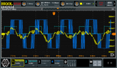
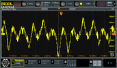
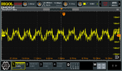
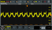
It is not laboratory experiment it is used for driving the hydraulic fluid for steering control and the requirement is motor should run at 3000 RPM, i have the market controller which is able to achieve the 3000 RPM, i will share the phase current and phase voltages and comparison with mine in some time. Please guide me to solve the issue.

The below is the gate drive circuit i have shown for 1 phase similarly another 2 gate drive circuit available.


1770493620605.png
The Mosfet section as below


1770493964558.png
 

Electric1

Nov 29, 2025
50
Joined
Nov 29, 2025
Messages
50
It is 3 phase current sensing and hall sensor based.(It is off road farming vehicle and runs at slow speed not very safety critical application).
 

Electric1

Nov 29, 2025
50
Joined
Nov 29, 2025
Messages
50
Phase current waveforms i have captured from standard controller and mine. The DC bus current and phase currents are high for the standard controller and hence speed i suppose.
100mv - 10A
I get around 50mV - 5A
DC bus current is 2.7A

Standard controller - It goes upto 15A,
DC Bus current is around 3.1A.
Can i improve my algorithm to increase the DC bus current? The way i tested is for the standard controller i need to control with throttle, whereas for my board hard coded to fixed value of throttle% max.
 

Attachments

  • MarketController_PhaseCurernts_UV_Hallsignals.png
    MarketController_PhaseCurernts_UV_Hallsignals.png
    103.4 KB · Views: 2
  • MarketControllerPhaseCurrents-1.png
    MarketControllerPhaseCurrents-1.png
    93 KB · Views: 2
  • MyBoardPhaseCurrents.png
    MyBoardPhaseCurrents.png
    88.9 KB · Views: 2
  • MyBoardPhaseCurrents-2.png
    MyBoardPhaseCurrents-2.png
    89.4 KB · Views: 2
Last edited:

Harald Kapp

Moderator
Moderator
Nov 17, 2011
14,271
Joined
Nov 17, 2011
Messages
14,271
Seems your circuit is incorrect. The typical application in the datasheet show a connection from the controller's VS pin to the source of the high-side MOSFET. I don't see this connection in your schematic:
1770624213362.png
 

Electric1

Nov 29, 2025
50
Joined
Nov 29, 2025
Messages
50
It is there the V signal from the VS is going to the V signal in the MOSFET diagram( I have shown U phase MOSFET)
3 MOSFET drivers U,V, W signals from VS pin going to U,V,W points of the MOSFET.
 

Electric1

Nov 29, 2025
50
Joined
Nov 29, 2025
Messages
50
Initially the boot strap capacitance value was 1uF, then i changed it to 4.7uF and observed an improvement in speed of 200 RPM, i tried increasing to 10uF but motor was not rotating. Now i want to check for around 6.8uF but it is not available, it is 0603 package and there no pcb slot to solder two capacitors. I need recommendation if i can solder one 4.7uF and 2.2uF capacitors one above the other, will it be possible then the capacitors will be in parallel and i can get around 4.7uF + 2.2uF = 6.9uF, the capacitors are of type X5R.

1770703300127.png
 

Delta Prime

Jul 29, 2020
2,987
Joined
Jul 29, 2020
Messages
2,987
I need recommendation if i can solder one 4.7uF and 2.2uF capacitors one above the other, will it be possible then the capacitors will be in parallel and i can get around 4.7uF + 2.2uF = 6.9uF, the capacitors are of type X5R.
Yes, you’re absolutely correct.
 

Electric1

Nov 29, 2025
50
Joined
Nov 29, 2025
Messages
50
I have done several changes and tested it

1. Changed the gate resistance from 22 Ohm to 10 Ohm, the observation is the ringing was observed on the Mosfet and on the Gate driver output. Initially with 22 Ohm the ringing was not present on the Mosfet.
2. Changed the boot strap capacitor with 6.8uF in place of 4.7uF the motor was not running then reverted back to 4.7uF.

3. Changed again the 10 Ohm resistor with 33 Ohm resistor, the motor was not running smoothly after some 2 mins observed that the DC bus current kept increasing beyond 2A and some abnormal sound from motor and finally 2 low side mosfets failed.

I want to know in case the delay time is high (in the case of 3), does the mosfets fail, any rule to be followed for the time constant. How do i ensure what @danadak is suggesting in post 12 am i following or not? Too many unknowns to figure out.:(
 
Top