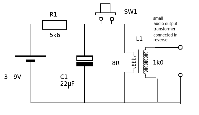
What is the purpose of the simulation? Is it to verify the posted example circuit works as advertised? Clearly that circuit will not produce a sustained output!
Have you measured the inductance and resistance of the primary and secondary windings on the ferrite-core transformer? Have you located and measured the capacitance of the alleged 22 μF capacitor? Have you determined by actual measurement whether the high-voltage oscillations on the secondary are damped or sustained? You need all this information before you can even consider simulating the actual device and creating a model of the circuit.
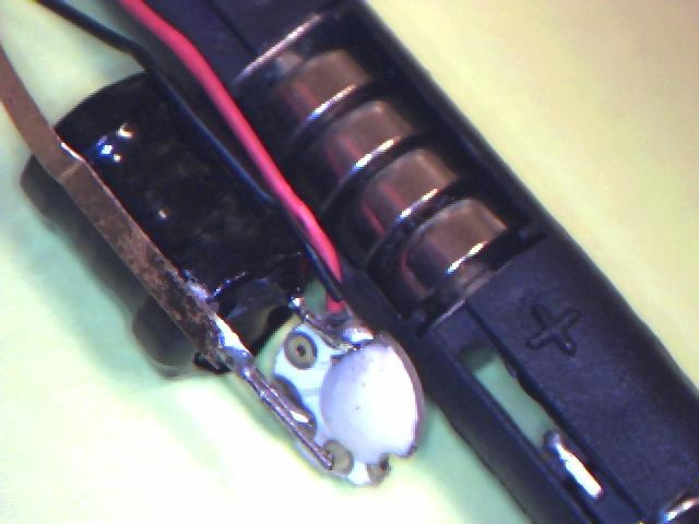
Maybe there is more to the particjular pen you have than meets the eye, What is that white blob? You need to really carefully disassemble it and identify all the components and draw up your own schematic, from which you can then begin a simulation model. Heck, this contraption might even contain a semiconductor wired up as an oscillator! In fact, it has to have an active semiconductor oscillator drawing power from the battery if it produces sustained oscillations when the switch is closed! There are circuits on the web that show a UJT (unijunction transistor) serving this purpose. If you really do experience an indefinitely sustained output when the switch is closed, there has to be an active semiconductor oscillator present to supply power to make up for losses. Why semiconductor? 'Cause I don't see no stinkin' vacuum tubes.
If you don't try to simulate the transformer, and just simulate the inductance of the transformer primary, you should be able to create a damped sine wave from the example circuit that lasts for as long as you please with a sufficiently large capacitance. The losses that cause damping will be mainly those in the charging resistor, since it is always effectively in parallel with the capacitor. Since you are just simulating the real operation, you can eliminate the charging resistor and battery entirely from the simulation and set an initial voltage on the capacitor at the start of the simulation. Then the losses will be whatever you specify for the inductor winding resistance, unless your capacitor model is lossy.
Before creating a model for simulation it helps to gain as much information about the real circuit as possible. Measure the oscillation frequency and see how it compares with the both the simulation oscillation frequency and the frequency you get if you plug in measured values for the capacitance and the inductance... assuming you can even find something in the pen that looks like a capacitor. If the high-voltage oscillations are sustained and not damped, the example circuit is definitely wrong. There has to be an active oscillator in there somewhere that draws power from the battery and makes up for losses in an LC resonant circuit. The capacitance part of LC may not even be a real component... just parasitic capacitance of the windings!
Interesting problem, explaining how a $2 item can produce a sustained shocking experience. Please tell us what you discover.