TRANSISTOR ATTENUATOR?

prateeksikka

Jun 19, 2004
736
Joined
Jun 19, 2004
Messages
736
HI ALL!
LET US CONSIDER A TRANSISTOR OPERATING IN ACTIVE REGION AS AN AMPLFIER.IT IS IN COMMON EMITTER CONFIG.IT HAS A GAIN OF SAY 50.I APPLY 1mV signal at i/p and i get 50mV at the collector.what would happen if i now apply a 50 mV signal at the collector?will it attenuate the signal?what do you think will it give 1mV at the base?Now the main thing .I have noticed that it does give 1mV at the base .it is surprising.I too was surprised that we cant have a reversed transistor operation.But when i carefully monitored the signal,the frequency of the signal was not the same as the one i had applied at the collector.tomorrow i am going to simulate it on ORCAD .any explanations? ::)
prateek


audioguru2

Apr 6, 2004
12,026
Joined
Apr 6, 2004
Messages
12,026
Feeding a signal to the collector varies the collector and emitter current. Therefore the emitter's resistance, Re, has a varying voltage across it. Since it is also in series with the base-emitter junction, the base voltage varies a little amount. The signal at the base is not the same frequency because of severe distortion caused by the exponential voltage change requirement at a base to make a linear change at a collector.
Two resistors connected in series to make a voltage-divider would make a much better attenuator. ;D 


prateeksikka

Jun 19, 2004
736
Joined
Jun 19, 2004
Messages
736
hi audioguru!
that means a voltage divider bias instead of a fixed bias can serve as a reversible transistor amplifier? :eek:
Although this is just a part of my interest, i know that for a very good quality attenuator i need just a pot!!! :)
prateek

 
A

Alun

Jan 1, 1970
0
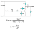
The good thing about transistor attenuators is the output impedance is very low and unaffected by the load unlike a potential divider.

trans_atten.GIF


audioguru2

Apr 6, 2004
12,026
Joined
Apr 6, 2004
Messages
12,026
I think the gain/loss is a lot more complicated:
1) Much of the input current through the 47k resistor is dumped in Rbias.
2) The input impedance of a transistor without an emitter resistance is fairly low so also attenuates the current through the 47k input resistor.
3) In addition to current gain, the transistor has some voltage gain (same thing?).
4) The feedback resistor feeds current into the 47k input resistor to cancel some of it, into Rbias, and into the low input impedance of the transistor.

I just finished doing my daughter's income tax so I don't want to calculate anything more.
A perfect application for a smart sim program or actual bench testing! ;D

An inverting opamp circuit is much easier to figure its gain/loss. 

 
A

Alun

Jan 1, 1970
0
Yes audioguru an op-amp would be much better.

The the current though Rf cancels out the low emitter impedance and Rbias this is an example of how negative feedback increases the input impedance. I've done a quick simulation and the loss is just under Rin/Rf, if you increased the open-loop gain by using a darlington or constant current collector load or even both then the loss would be damn near Rin/Rf.


audioguru2

Apr 6, 2004
12,026
Joined
Apr 6, 2004
Messages
12,026
Alun said:
this is an example of how negative feedback increases the input impedance.
Hi Alun,
You mean the negative feedback decreases the input impedance, don't you?
The input of the transistor is approaching being a virtural ground. I think that the input impedance is very close to the value of the 47k input resistor.

Is your sim program any good? Frequently they screw-up on complicated issues like this one.  ;D
 
A

Alun

Jan 1, 1970
0
audioguru,
At DC the current through Rf if added to the input current therefore increasing the input impedance this is why Rbias makes very little difference since the base has a very low impedence anyway and 700mV across 2K issn't going to cause much current to flow, and yes you're right the input impedance will be about the value of Rin. This circuit is a lot better than a potential divider but nowhere neard as good as an ap-amp.


audioguru2

Apr 6, 2004
12,026
Joined
Apr 6, 2004
Messages
12,026
Hi Alun,
Never mind the DC current, the thing is cap-coupled.
The junction of the input resistor and the feedback resistor is a low impedance point at AC because as the input swings positive, the output swings negative and vice-versa. Therefore the junction is a virtural-ground like the inverting input pin on an inverting opamp amp. ;D


prateeksikka

Jun 19, 2004
736
Joined
Jun 19, 2004
Messages
736
HI AUDIOGURU!
FOR OPAMP TOO ! THAT HELL OPAMP!
COULD YOU PLEASE TELL ME WHAT IS THIS VIRTUAL GROUND?WHY DO WE ASSUME IT?
I AM CONFUSED WITH AUTHORS WRITING V1=V2 AT 2 PINS OF THE OPAMP.
AND ONE IS AT VIRTUAL GROUNG SO V2=0,HENCE V1=V2=0.
HOW IS THIS?
???PRATEEK

 
A

Alun

Jan 1, 1970
0
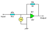
The op-amp has a very high gain - some op-amps have a gain > 1 million.

Because the gain is so high, the output is always 1 million times greater than the input the input can be considered to be 0. For example, if the outputs 1V, and the input (Vd on my circuit) would be 1uV which for all intents and purposes is virtually 0V.

Opamp_atten.GIF


audioguru2

Apr 6, 2004
12,026
Joined
Apr 6, 2004
Messages
12,026
A little confusing.
In Alun's inverting opamp circuit, if the output is -1V, then the input of the opamp is +1uV and the circuit's input to the 47k resistor is +0.212767V.
Due to the opamp's extremely high gain and extemely high input impedance, Rf and Rin simply form a voltage divider to determine the gain of the circuit.  ;D


prateeksikka

Jun 19, 2004
736
Joined
Jun 19, 2004
Messages
736
hi audioguru!
even if there is infinite resistance between the 2 pins even then the signal will exist between the 2 pts equal to the applied signal say 5mV.how can i/p signal be considered as 0 even if it is present?
prateek ::)

 
A

Alun

Jan 1, 1970
0
Oh sorry of course -1uV with 1V input because it's inverting  silly me.;D Rf is providing feedback, some of the output is fed back to the input and as it's an inverting amplifier the output will be opposite to the input and cancel it out to some extent, hence the feedback is negative, the ratio of Rf and Rin deturmines the amout of negative feedback.

The principle is the same with my transistors circuit, the base is always near ground at 700mV and the transistor has a gain of about 100, Rf and Rin reduce it to 10/47, the transisto has a lower gain than the op-amp so in practice the gain will be a bit below 10/47.

 
A

Alun

Jan 1, 1970
0
prateeksikka,
It isn't considered to be exactly 0V, but near 0V, that's why it's called a virtual ground, and not just ground. If the input to the circuit is 5V and Vd is only 5mV, 5mV is nothing compared to 5V in pracitice Vd will be a lot smaller than 5mV because the gain of a cheap op-amp is a lot higher than 1000.


audioguru2

Apr 6, 2004
12,026
Joined
Apr 6, 2004
Messages
12,026
Hi Prateek,
When the opamp has a gain of a few million, your meter across its inputs will read zero. In this inverting opamp circuit, the negative feedback in Rf cancels the signal in Rin.


prateeksikka

Jun 19, 2004
736
Joined
Jun 19, 2004
Messages
736
hi there!
can we even then conclude that even if it has a high gain,the o/p can never exceed the fixed supply.I may even generalize that voltage at any point in a circuit can never exceed the supply! :)
prateek


EdwardM

Apr 12, 2005
246
Joined
Apr 12, 2005
Messages
246
Hi prateeksikka

I may even generalize that voltage at any point in a circuit can never exceed the supply! Smiley
Nearly correct but consider what happens when an inductance suddenly loses its current  ;D

Best of Luck

Ed
 

prateeksikka

Jun 19, 2004
736
Joined
Jun 19, 2004
Messages
736
OFCOURSE BUDDY!
WE HAVE TRANSFORMERS TOO AND L-C-R CIRCUITS TOO,BUT ONLY THE INSTANTANEOUS VOLTAGE CAN EXCEED THE SUPPLY NOT THE RMS OR AVERAGE OTHERWISE ALL POWER PLANTS ARE USELESS! ;D
PRATEEK

 
Top