Getting Started with Adafruit.io IoT Cloud Platform
In the last tutorial, we examined How to connect your IoT devices to the Arduino IoT Cloud, and we saw how to send and receive data, from and to the cloud. With multiple cloud solutions available for IoT devices, there might be a need for you to work with one not as traditional as the Arduino IoT cloud.
In the last tutorial, we examined How to connect your IoT devices to the Arduino IoT Cloud, and we saw how to send and receive data, from and to the cloud. With multiple cloud solutions available for IoT devices, there might be a need for you to work with one not as traditional as the Arduino IoT cloud. To help you prepare, for today’s tutorial, we will look at how to build IoT devices that interact with the Adafruit IO.

Adafruit IO represents Adafruit’s desire to continually develop solutions that support makers and hardware enthusiasts in general. It is essentially an integrated cloud service for IoT devices designed primarily, like most other cloud services, to retrieve and store data. However, to make things more suitable for use by its target audience, Adafruit included features that facilitate real-time data visualization using graphs, gauges, etc., Email/webhook notifications, and Control of devices from the internet. It also features IFTTT and zapier integrations which give us the ability to interact with 100s of web services like RSS feeds and Twitter. It comes with a limited but wholly sufficient free plan as well as a paid plan which gives full unrestricted access for around 10$/month.
IoT devices typically perform tasks involving; either sending data to the cloud or receiving data commands from the cloud, as such, in today’s tutorial will have a two-part tutorial to cover both aspects. For the first part, we will obtain temperature, humidity, atmospheric pressure, and light intensity data from the environment and send it to Adafruit IO where it will be displayed on a dashboard and updated every 2s. To provide an offline view of the data, we will use a 1.44 Adafruit TFT LCD display. You can check some of our past tutorials using the 1.44″ TFT display to better understands how it works.
The second part of the tutorial will be used to demonstrate how to control the device from the cloud. We will set up an on/off button on the cloud which when pressed, will show the corresponding text on a display.
To make all of this happen, at the center of today’s project is the Arduino MKR WiFi 1010 board. It is one of the latest boards of the Arduino line and is a significantly improved version of the MKR 1000 WiFi. It’s equipped with an ESP32 module made by U-BLOX with the aim of speeding up and simplifying the development of WiFi-based IoT applications, leveraging on the flexibility and low power consumption of the ESP32 module.
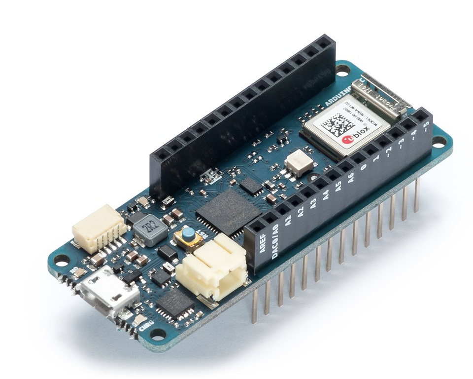
The board is made up of three main blocks:
- SAMD21 Cortex-M0+ 32bit Low Power ARM MCU
- U-BLOX NINA-W10 Series Low Power 2.4GHz IEEE® 802.11 b/g/n Wi-Fi
- ECC508 Crypto Authentication
The MKR WIFI 1010 includes a 32-bit computational power, the usual rich set of I/O interfaces associated with Arduino boards, and a low power Wi-Fi with a Cryptochip for secure communication using SHA-256 encryption. All these features can easily be programmed using Arduino Software (IDE) for code development and programming.
Other key components we will use include the Arduino MKR ENV shield and the Arduino MKR RGB Shield.
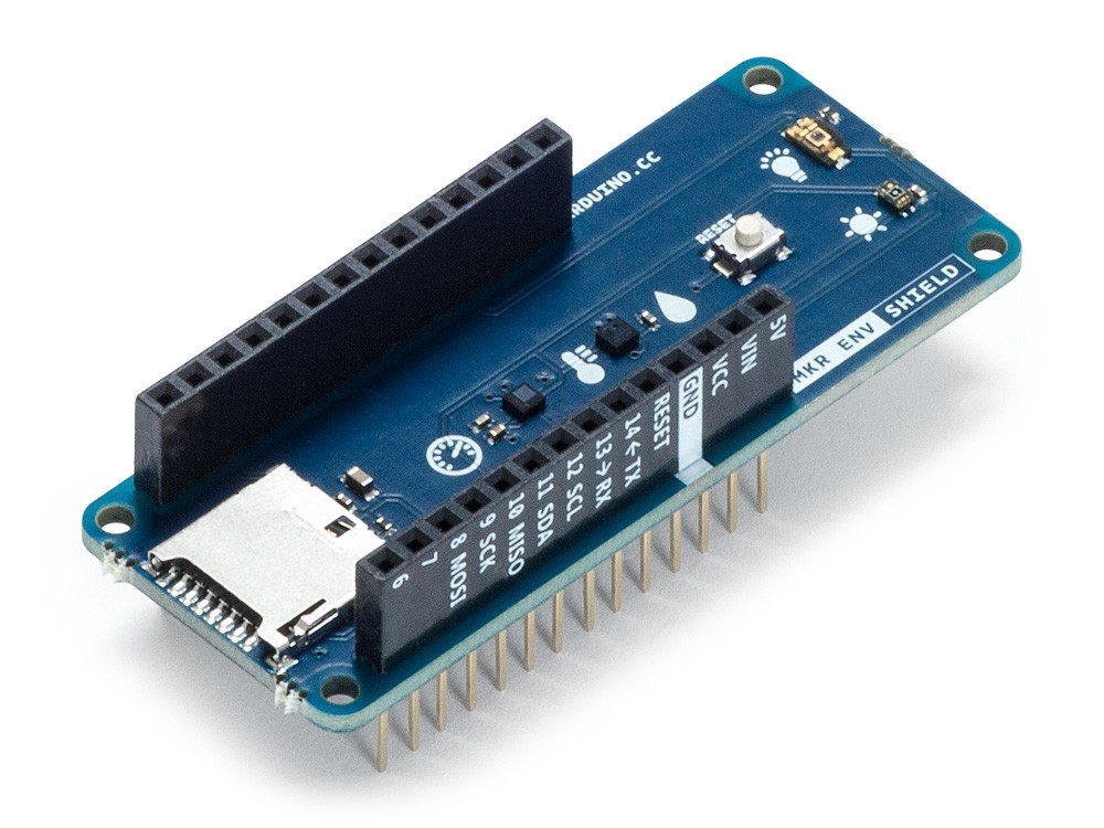
Arduino MKR ENV shield allows the MKR Arduino board series to acquire environmental data via a plethora of inbuilt sensors including;
- Atmospheric pressure
- Temperature and humidity
- Ultraviolet UVA intensity Ultraviolet UVB intensity,
- UV Index (calculated)
- Light intensity (in LUX)
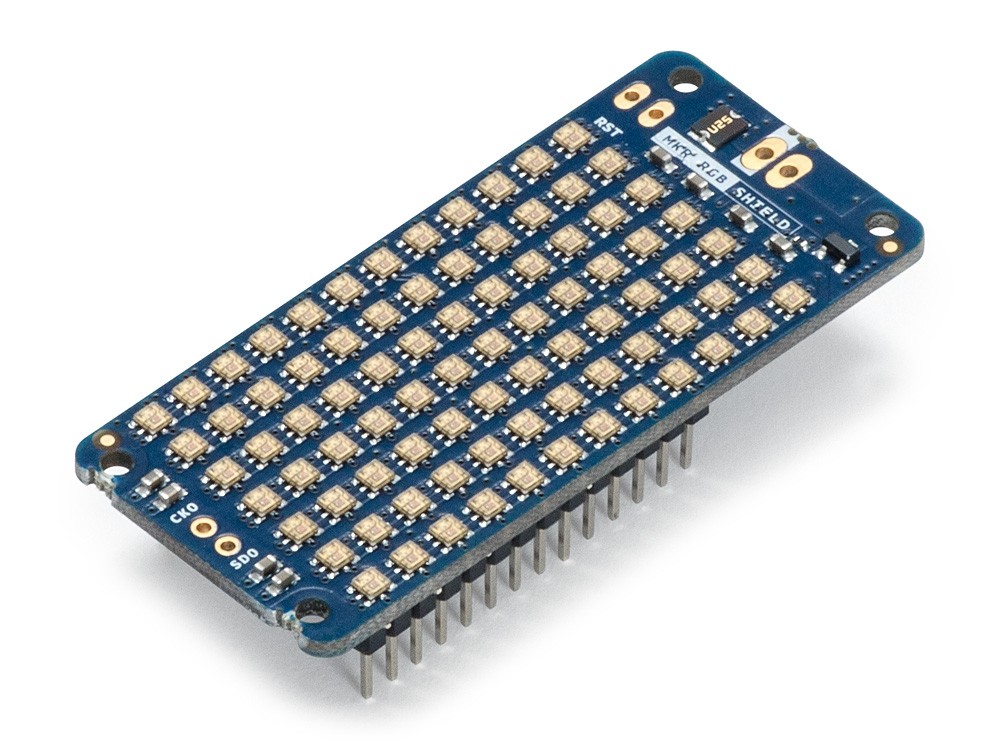
The Arduino MKR RGB, on the other hand, is made up of an array of super bright LEDs which, with the use of a superb library, allows the display of static and scrolling text in minutes. It will be used to display a text corresponding to the state of the on/off button on the Adafruit IO dashboard.
At the end of this tutorial, you would know how to build IoT devices that are based on the Adafruit IoT cloud and for those who may be new to the MKR series of boards, you would know, developing basic and complex projects based on them.
Required Components
The following components are required to build both parts of this tutorial;
- Arduino MKR WiFi 1010
- Arduino MKR ENV Shield
- Arduino MKR RGB Shield
- Adafruit 1.44TFT Display
- Breadboard
All of these components can be bought from the Arduino store or from electronics components sales platforms like Seeed Studio, and Aliexpress.
Schematics
As mentioned during the introduction, there are two parts to this tutorial as such, we will have two schematics.
Schematic 1: Sending data to the cloud
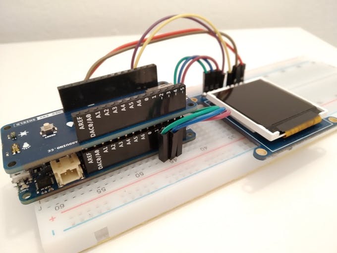
For the first part, we will use the Arduino MKR WiFi 1010 board, the MKR ENV Shield, and the 1.44″ TFT Display. The MKR ENV Shield, like the name implies, comes as a shield and is plugged on top the MKR WiFi 1010, leaving us with just the connections between the MKR WiFi 1010 and the 1.44″ TFT display. Connect as shown in the fritzing schematics below.
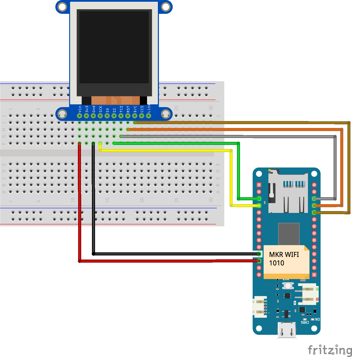
To make connections easier to follow, the pin to pin map of the connection between the MKR WiFi 1010 and the 1.44″ TFT is shown below.
1.44″ TFT – Arduino MKR WiFi
Vin - VCC
GND - GND
SCk - D9(SCK)
SI - D8(MOSI)
TCS - D3
RST - D2
D/C - D1
After connecting the components, your setup should look like the one in the image below.
Schematic 2: Receiving Data from the Cloud
For the second half of the project (Receiving Data from the cloud), we will use Arduino MKR WiFi 1010 and the Arduino MKR RGB Shield. While adjustments could be made to accommodate the sensors on the ENV shield, we will do it this way to keep things short and simple.
Just like the MKR ENV Shield, the RGB Shield also comes as a shield and should be plugged on the MKR WiFi 1010 as shown in the image below.
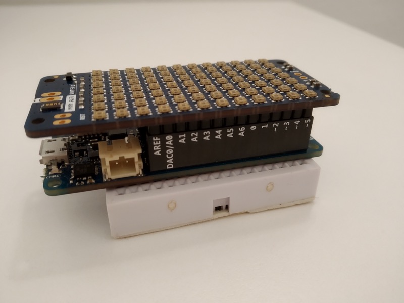
Since you will most likely use the same MKR WiFi 1010 for both parts, you can complete the code upload of one part before connecting the second part.
Programming
Just like we did under the schematics, we will also split this into two parts. The first part will be for programming the board to send the data as we highlighted initially, and the second part will be to receive data from the IoT Cloud and display on the RGB shield. For both parts, we will use the WIFINNA library and the Adafruit IO Rest API. You could also choose to use the Adafruit IO library.
Part 1: Sending data to the Cloud
Before we start writing the code, we need to create the “feeds” on Adafruit.io to which the data will be reported. The feeds will be placed in a group to make it easy for us to manage and send data with a single command. Follow the steps below to do this;
-Visit https://io.adafruit.com/ and login or create an account if you do not already have.
-Logging in should take you to the Adafruit IO home page. Click the feeds button, it should take you to a page with a list of all the feeds that have been created on your account. Click on the “actions” button and select “create a new group” from the dropdown menu.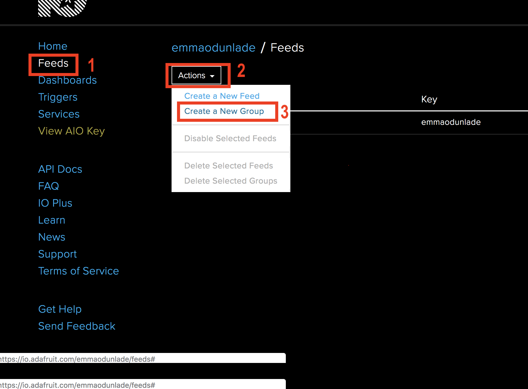
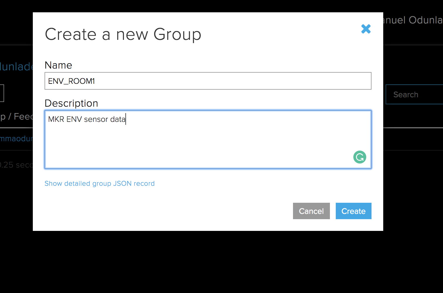
-Enter the name of the group and a description and click the create button.
-With the group created, we need to add four feeds under it, each one for the parameters we will monitor. Click on the group you just created, when the new page opens, click on the action button again and select “Create a new feed“.
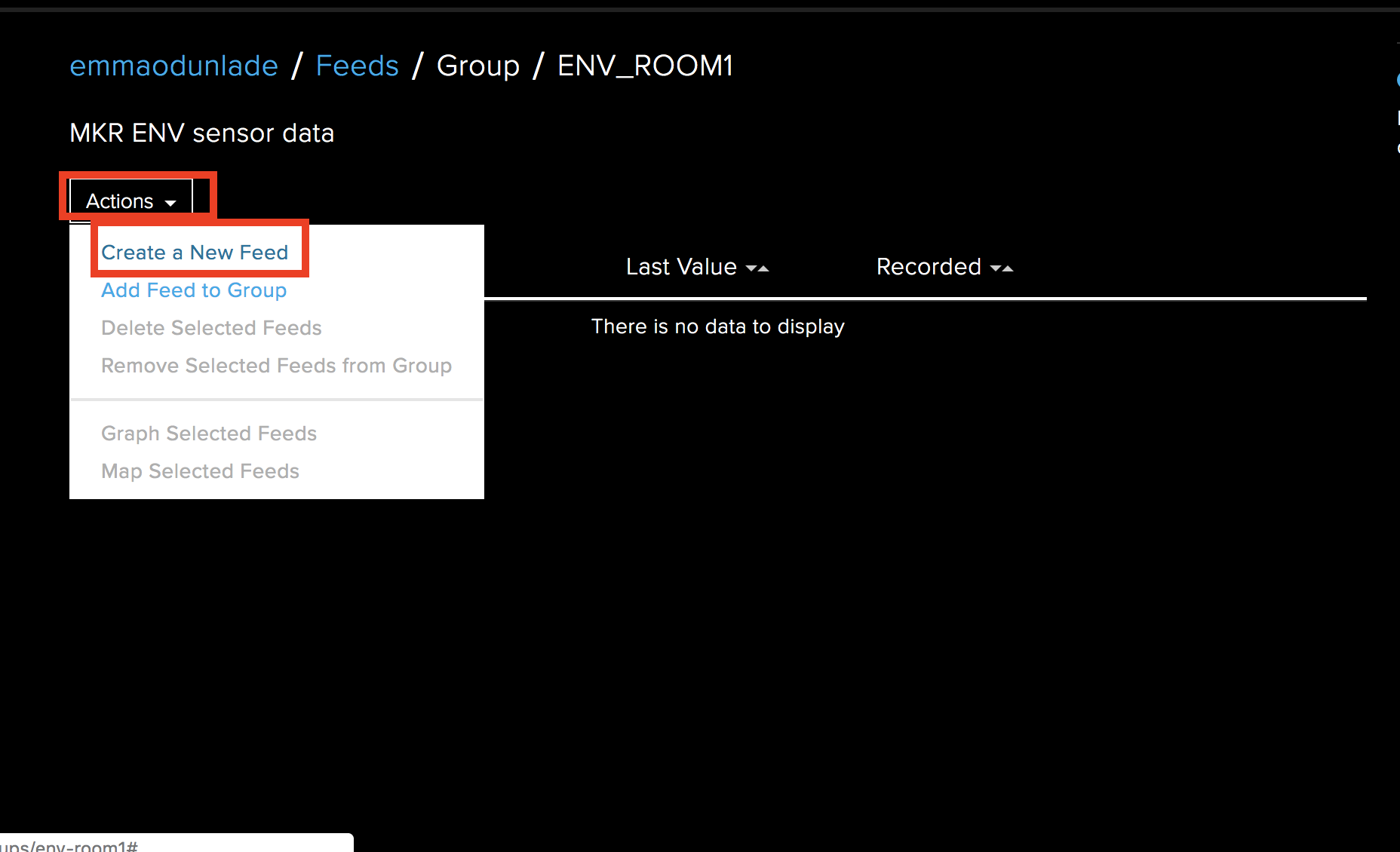
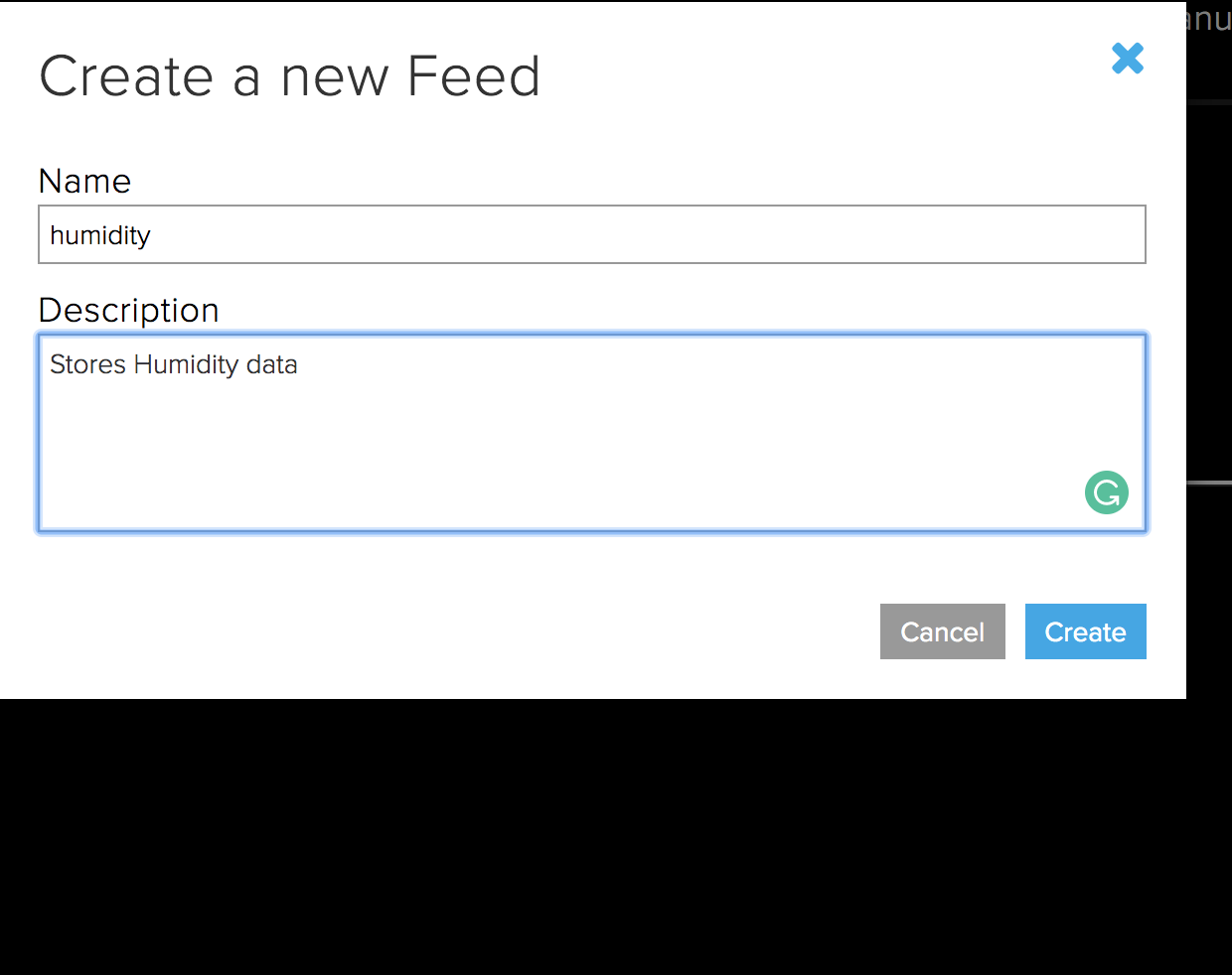
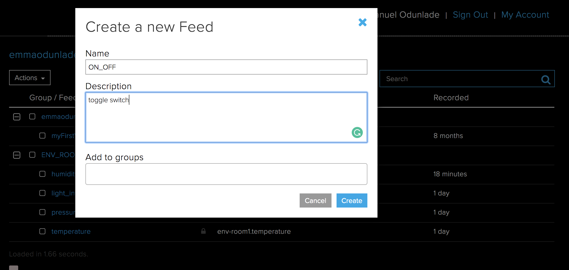
-In the dialogue box that opens, enter the name of the feed, and a description then click the create button.
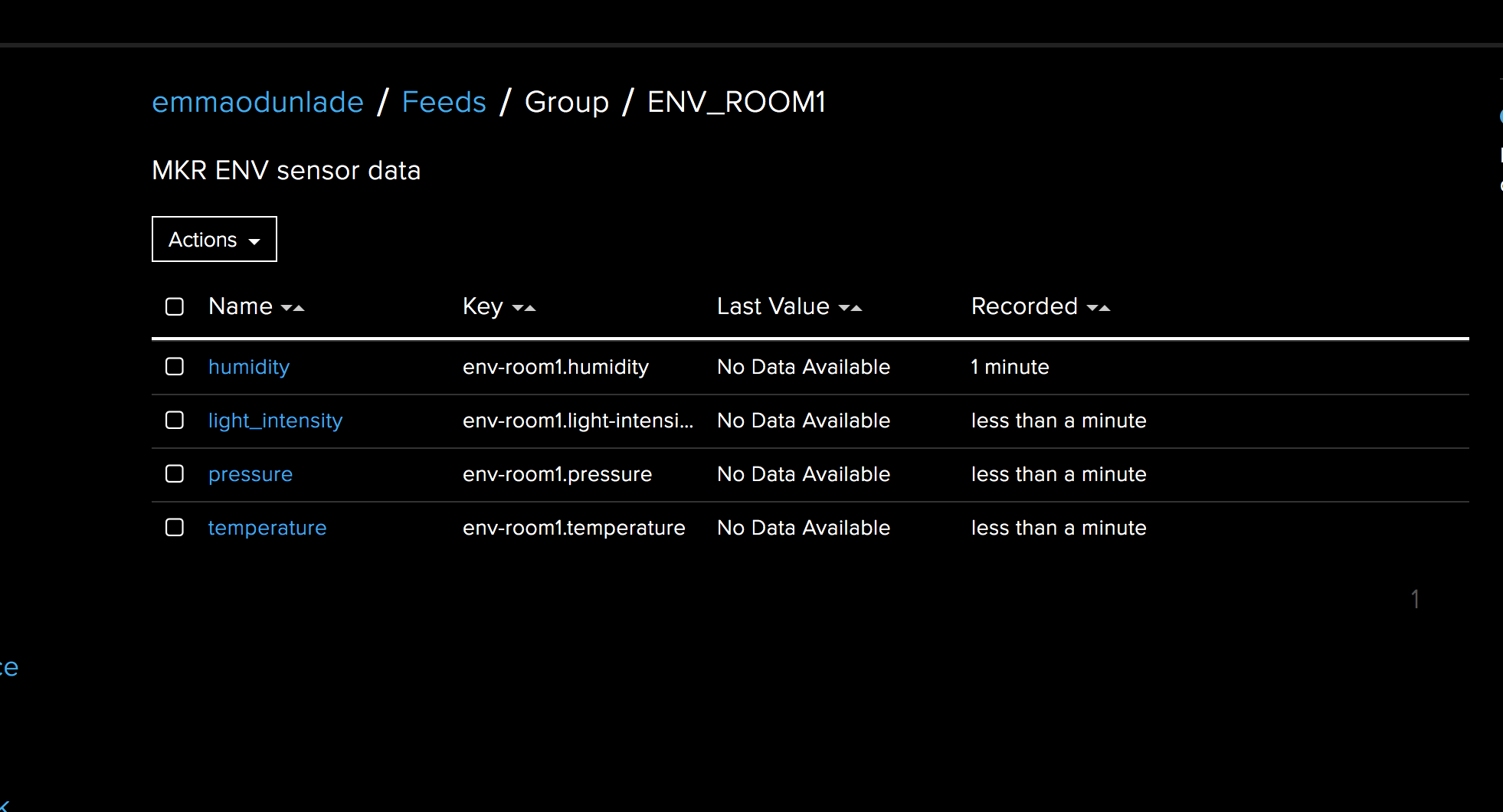
-Repeat step 4 and 5 for all the other parameters; temperature, humidity, Light Intensity, and pressure. When done, the group feed should look at the image below.
By clicking on each of the feeds and scrolling down, a history of data stored in the feed can be seen, however, to make it more interactive and user-friendly, we will create a dashboard to host the data from all the four feeds. To do this, follow the steps below.
-Click on the dashboard button just below feeds on the right-hand side of the IO page, just below feeds.
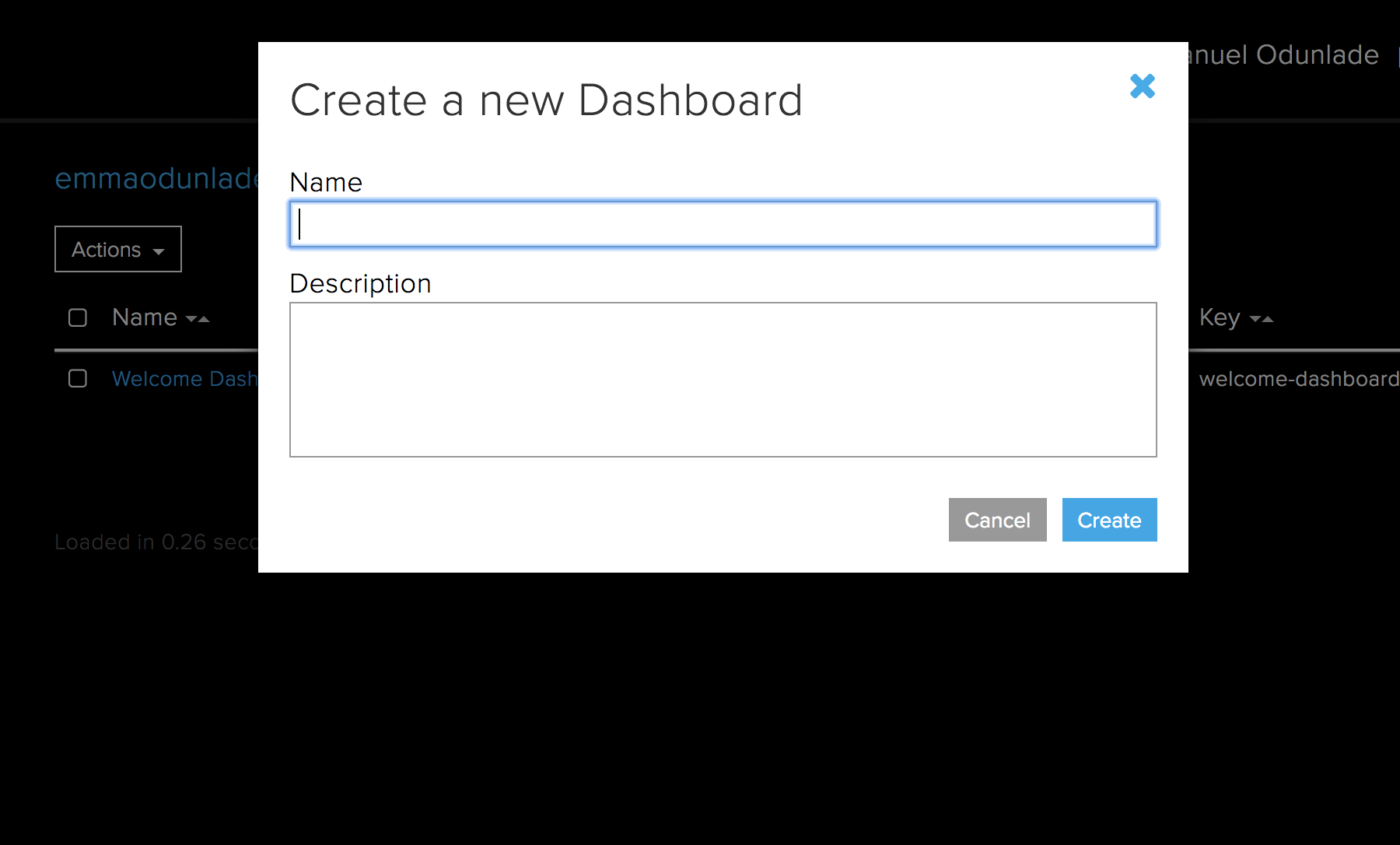
-It will open a list of all the dashboards you have created. If you have less than four(the free access to Adafruit IO allows just four dashboards), click on the action button at the top of the page and select “create a new dashboard“.
-Enter the name and description of the dashboard in the dialogue box that opens and click the “create” button.
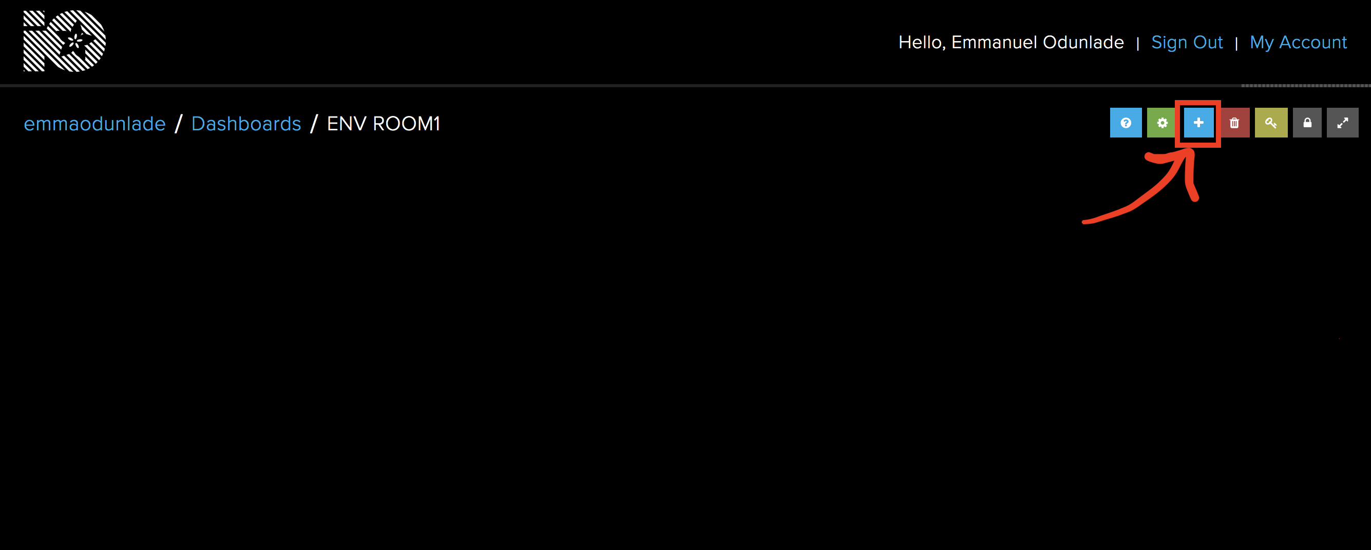
-Click on the dashboard you have created, it should open a new window. On the window, click on the “+” Icon to start adding blocks (widgets) to the dashboard.
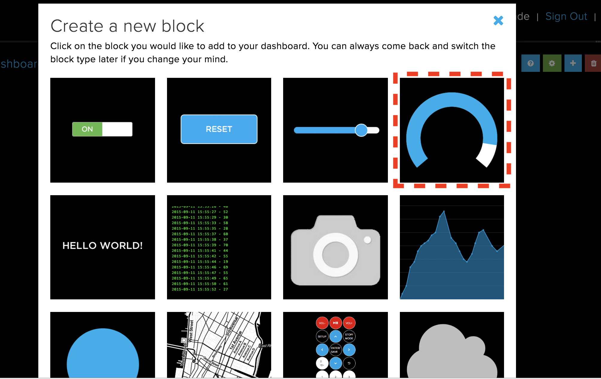
-For this tutorial, we will use a gauge widget to represent each of the parameters to be monitored. Click on the Gauge block.
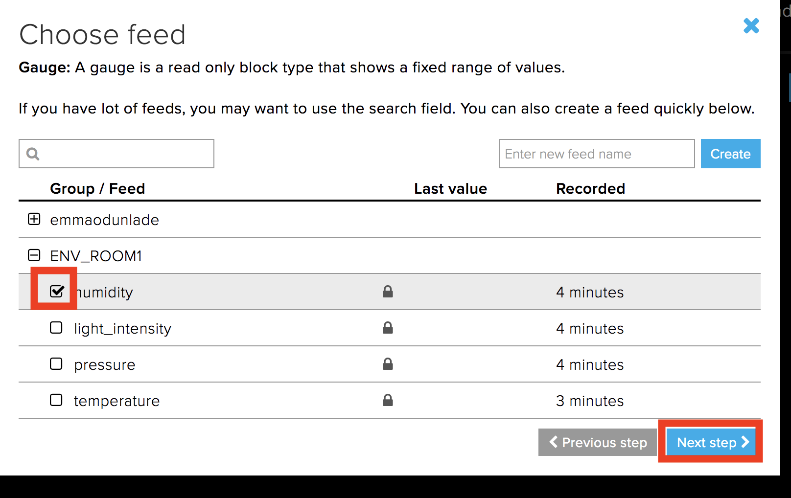
-Clicking on the gauge block will open a dialogue block to enable you to set the properties of the block. Select the feed to whose data will be displayed on that block and hit the next button.
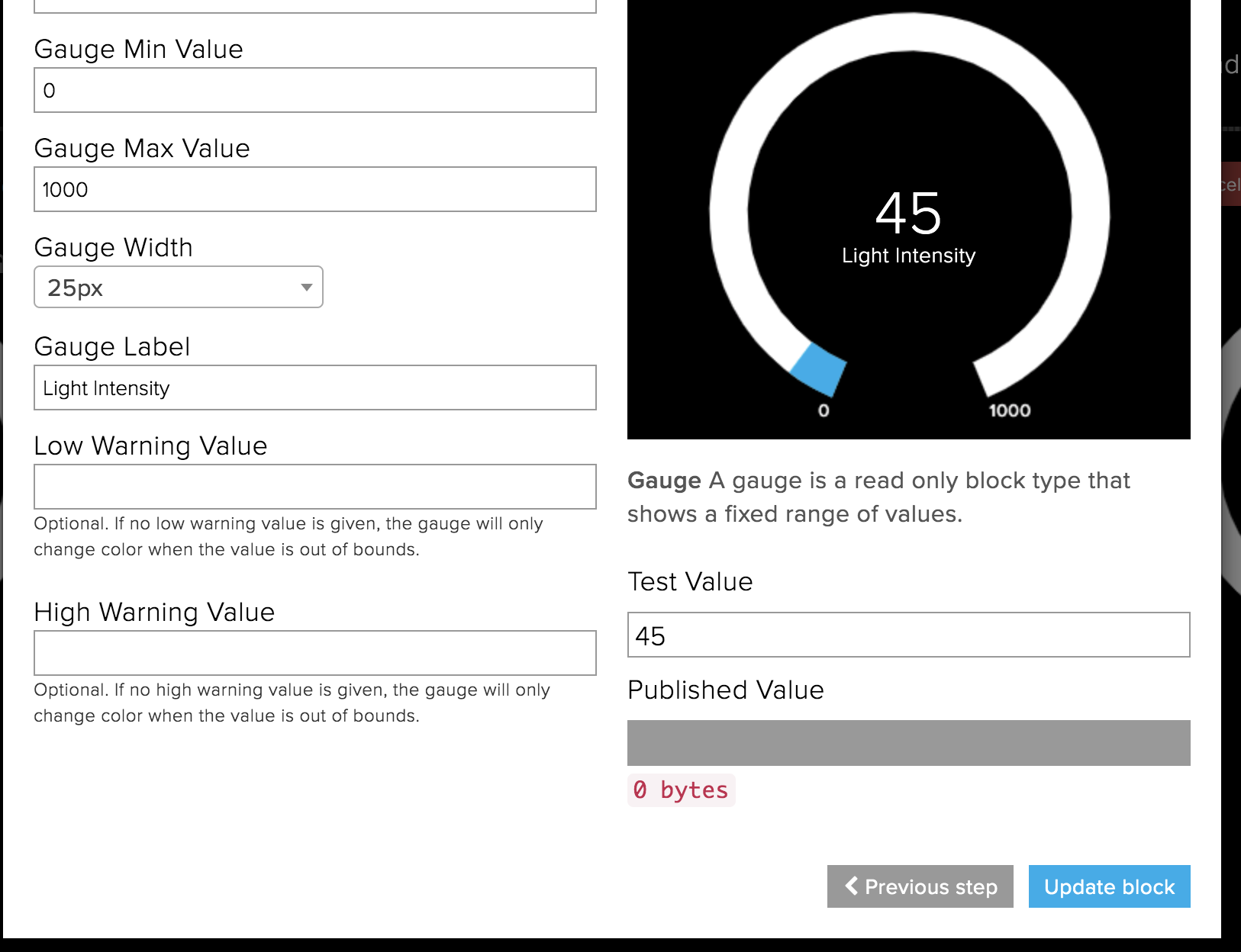
-On the next page, Enter the label you want to be displayed on the gauge (best if its the same name as the field for easy referencing), set the min and max values as desired, then hit the create block button.
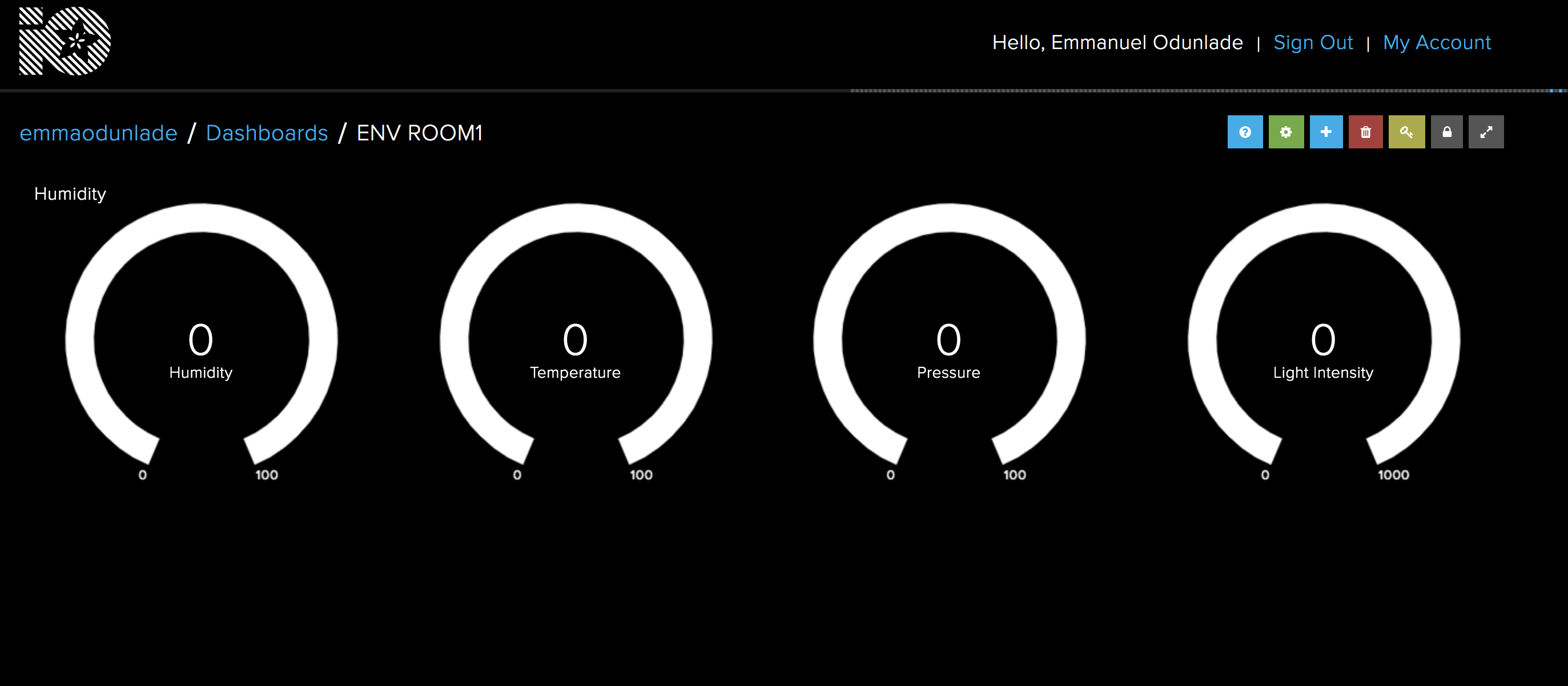
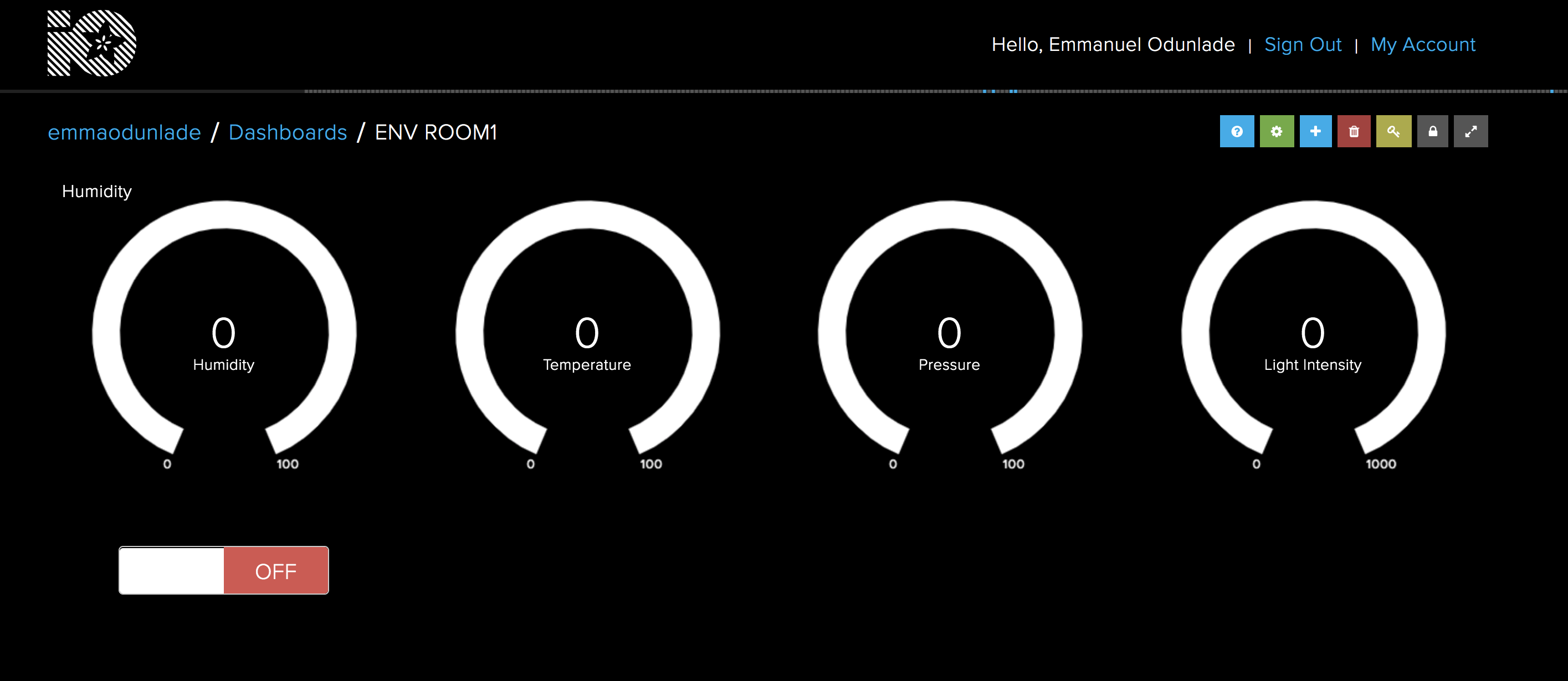
-Repeat step 4 – 7 for the remaining feeds. Your Dashboard when done should look like the one in the image below. The blocks can be rearranged by clicking the settings icon and dragging the blocks until they are side by side. Since no data has been uploaded to it yet, all values will be at zero.
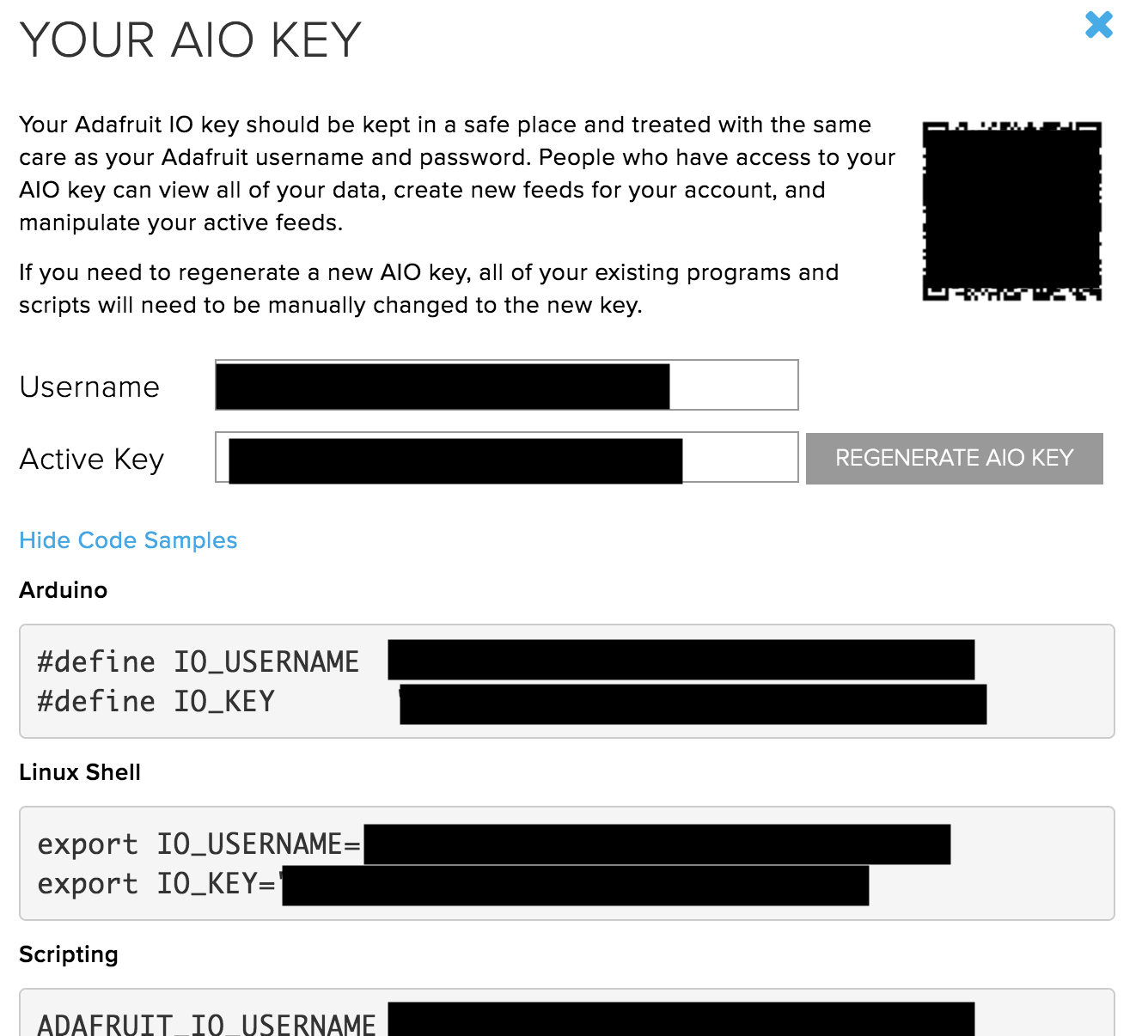
With that done, we proceed to obtain the last element of the Adafruit IO that will be used in our code; the AIO key. The AIO key is an alphanumeric key that allows secure communication between your device and Adafruit IO. Go to your IO home page, just below services after dashboard you will see the view AIO key button. Click on it to open a page similar to the image below. Copy the AIO key for later use.
With this done, we are now ready for the code.
As mentioned earlier, we will use the WIFININA library along with the Adafruit IO Rest API but for this part, in addition to those libraries, we will also use the Arduino JSON library, the Adafruit GFX library, the Adafruit ST7735 library, and the MKR ENV library. The Arduino JSON library will be used to group the data when sending to Adafruit IO, while the ST7735 library facilitates communication with the 1.4″ TFT display, and the GFX library makes it easy to display graphics and the text on the TFT. The MKR ENV reduces the amount of code needed to obtain data from the ENV shield.
As usual, I will do a quick run through the code to explain the concepts involved.
We start the code by including all the libraries that we will use. To make the code modular and clean, a header file (called arduino_secrets.h) was created (in the same folder as the sketch) to store passwords and sensitive data like the AIO key and wifi credentials, include this too along with other libraries that have been mentioned.
#include <ArduinoJson.h>
#include <avr/dtostrf.h>
#include <SPI.h>

////////////////////////////////
#include <Arduino_MKRENV.h>

////////////////////////////////
#include <Adafruit_GFX.h>     // Core graphics library
#include <Adafruit_ST7735.h>  // Hardware-specific library for ST7735

/////////////////////////
#include <WiFiNINA.h>
#include "arduino_secrets.h"
Next, we declare the pins of the Arduino to which the Chip Select (CS), Reset (RST) and DC pins of the TFT LCD are connected (as described under the schematics section) and create an instance of the ST7735 library with the variables mentioned above as arguments.
#define TFT_CS        3
#define TFT_RST       2
#define TFT_DC        1

Adafruit_ST7735 tft = Adafruit_ST7735(TFT_CS, TFT_DC, TFT_RST);
Next, we create the variables to hold the WiFi credentials, the server address, posting interval and a “last connection time” variable to help determine when the next update to the server is due. We also initialize the WiFi Client Library.
char ssid[] = SECRET_SSID;         // your network SSID (name)
char pass[] = SECRET_PASS;         // your network password (use for WPA, or use as key for WEP)
int status = WL_IDLE_STATUS;
char server[] = "io.adafruit.com"; // name address for Adafruit IOT Cloud

unsigned long lastConnectionTime = 0;              // last time you connected to the server, in milliseconds
const unsigned long postingInterval = 7000;       // delay between updates, in milliseconds
Next, we create the variables that will be used to store the data to be obtained from the ENV Shield.
float _temperature = 0;
float _humidity = 0;
float _pressure = 0;
float _lux = 0;
With this done, we move to the setup function.
We start by initializing Serial communication to help with debugging the code, setting the baud rate to 9600. After this, we initialize the display, change the screen color to black, initialize the ENV shield, and use the connectToWiFi() function to connect to the specified SSID.
void setup() {

  Serial.begin(9600);
  //while (!Serial); // wait for serial port to connect. Needed for native USB port only

  // Init ST7735R chip, green tab
  tft.initR(INITR_144GREENTAB);

  tft.fillScreen(ST77XX_BLACK);

  // Init MKR ENV shield
  if (!ENV.begin()) {
    Serial.println("Failed to initialize MKR ENV shield!");
    while (1);
  }

  connectToWIFI();

}
Next, we write the voidloop() function.
The code for the voidloop() is simple thanks to the libraries we are using and a few functions.
We start the voidloop() by checking if the posting interval has elapsed as the Adafruit IO has a specified interval of seconds between data uploads for free access. If the time has elapsed, we then use the readsensor() function to obtain data from the ENV shield and call the displayValuesOnTFT() function to display the values. The displayValuesOnSerial() function is used to print the values on the serial monitor for debugging and the httpRequest() function is used to send the data to the cloud.
void loop() {

 // if 7 seconds have passed since your last connection,
  // then connect again and send data:
  if (millis() - lastConnectionTime > postingInterval)
  {
    readSensors();
    displayValuesOnTFT();
    displayValuesOnSerial();
    httpRequest(); // send data to Cloud
  }

}
To take a closer look at these functions,
The readsensors() functions contain code to probe the ENV shield for each of the parameters we intend to measure and equate it to the corresponding variable name.
void readSensors()
{
  _temperature = ENV.readTemperature();
  _humidity = ENV.readHumidity();
  _pressure = ENV.readPressure();
  _lux = ENV.readLux();
}
The HTTP request function combines the values from the readsensor() function together in a JSON format (Key and value pair) and sends to Adafruit IO. The status of the data upload is displayed on the TFT and the variable; lastConnectionTime is updated to determine when the next data is sent.
void httpRequest()
{


/*
 * https://io.adafruit.com/api/docs/#operation/createGroupData
 *
 * POST /{username}/groups/{group_key}/data
 *
 * JSON:
 *
{
  "location": {
    "lat": 0,
    "lon": 0,
    "ele": 0
  },
  "feeds": [
    {
      "key": "string",
      "value": "string"
    }
  ],
  "created_at": "string"
}
 */

  const size_t capacity = JSON_ARRAY_SIZE(3) + 3*JSON_OBJECT_SIZE(2) + 2*JSON_OBJECT_SIZE(3) + 130;
  StaticJsonDocument<capacity> doc;

   // Add the "location" object
  JsonObject location = doc.createNestedObject("location");
  location["lat"] = 0;
  location["lon"] = 0;
  location["ele"] = 0;

  // Add the "feeds" array
  JsonArray feeds = doc.createNestedArray("feeds");
  JsonObject feed1 = feeds.createNestedObject();
  feed1["key"] = "temperature";
  feed1["value"] = _temperature;
  JsonObject feed2 = feeds.createNestedObject();
  feed2["key"] = "humidity";
  feed2["value"] = _humidity;
  JsonObject feed3 = feeds.createNestedObject();
  feed3["key"] = "pressure";
  feed3["value"] = _pressure;
  JsonObject feed4 = feeds.createNestedObject();
  feed4["key"] = "light_intensity";
  feed4["value"] = _lux;


  // close any connection before send a new request.
  // This will free the socket on the Nina module
  client.stop();

  Serial.println("\nStarting connection to server...");
  if (client.connect(server, 80))
  {
    Serial.println("connected to server");
    // Make a HTTP request:
    client.println("POST /api/v2/" IO_USERNAME "/groups/" IO_GROUP "/data HTTP/1.1");
    client.println("Host: io.adafruit.com");
    client.println("Connection: close");
    client.print("Content-Length: ");
    client.println(measureJson(doc));
    client.println("Content-Type: application/json");
    client.println("X-AIO-Key: " IO_KEY);

    // Terminate headers with a blank line
    client.println();
    // Send JSON document in body
    serializeJson(doc, client);

    // note the time that the connection was made:
    lastConnectionTime = millis();

    testdrawtext(5,120,"data sent to Cloud!", ST77XX_WHITE,1);
    Serial.println("data sent!");

  } else {
    // if you couldn't make a connection:
    testdrawtext(10,120,"connection failed!", ST77XX_WHITE,1);
    Serial.println("connection failed!");
  }


}
The displayValuesOnTFT() function, on the other hand, is used to display the values from the readsensor() function on the TFT display. The function starts by converting all the values to the string after which they are displayed using the testdrawtext() function.
The testdrawtext() function takes several arguments including the screen coordinates where the text is to be written, the text/value to be written, color and font size. We have covered the use of the st77xx displays in several tutorials, you can check them out to learn more about the functions.
void displayValuesOnTFT()
{

  // float to char conversion
  char temperature[6];
  char humidity[6];
  char pressure[7];
  char lux[8];

  dtostrf(_temperature, 5, 2, temperature);
  dtostrf(_humidity, 5, 2, humidity);
  dtostrf(_pressure, 5, 2, pressure);
  dtostrf(_lux, 6, 2, lux);

  // Display on TFT
  tft.fillScreen(ST77XX_BLACK);

  testdrawtext(0,5,"T:", ST77XX_RED,2);
  testdrawtext(25,5,temperature, ST77XX_RED,2);
  testdrawtext(110,10,"C", ST77XX_RED,1);

  testdrawtext(0,35,"H:", ST77XX_GREEN,2);
  testdrawtext(25,35,humidity, ST77XX_GREEN,2);
  testdrawtext(110,40,"%", ST77XX_GREEN,1);

  testdrawtext(0,65,"P:", ST77XX_YELLOW,2);
  testdrawtext(25,65,pressure, ST77XX_YELLOW,2);
  testdrawtext(110,70,"kPa", ST77XX_YELLOW,1);

  testdrawtext(0,95,"L:", ST77XX_WHITE,2);
  testdrawtext(25,95,lux, ST77XX_WHITE,2);
  testdrawtext(110,100,"Lux", ST77XX_WHITE,1);

}
The complete code for this part is available below and also attached under the download section. You can either jump straight to the demo section from here or follow part 2.
Part 2: Receiving Data from the cloud
As mentioned during the introduction, for this second part, we will examine how you can send commands from the cloud to the device to initiate actions. For this example, we will toggle a switch on the dashboard and a text(on/off) corresponding to the state of the switch will be displayed on the RGB shield.
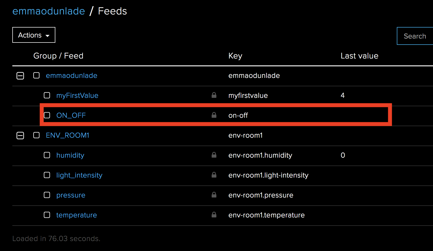
We start by creating a new feed called ON_OFF. This time under the defaults group.
Next, we turn the feed history off so only the current data is available.
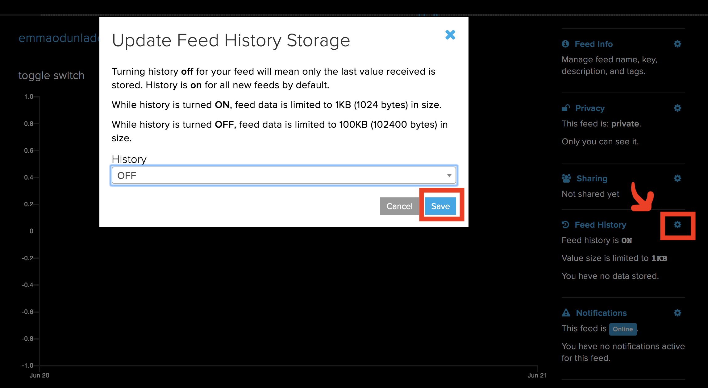
It should now be visible with the other feeds as shown below.
Next, we go to the dashboard we created earlier, click the “+” sign and select a toggle switch widget. Fill that dialog box that opens, entering the feed name and other details just like we did for the ones in the first part. You can decide to do this on a new dashboard since we are not focusing on combining both parts of the tutorial.
With this done, we can proceed to write the code. Just like the first part, in addition to the Adafruit IO REST API (v2.0.0) and the WIFININA library, we will use the MKR RGB Library, the Arduino Json Library and the Arduino Graphics library.
As usual, we start the code by including the libraries that we will use for the project.
#include <ArduinoJson.h>
#include <ArduinoGraphics.h>
#include <Arduino_MKRRGB.h>
#include <WiFiNINA.h>
#include "arduino_secrets.h"
Next, we create variables to hold the WiFi credentials. These variables must be entered in the Arduino_Secrets.h file which it is needed to be placed in the same folder as the sketch. We also specify the IO Server and create an object of the WiFi Client Library.
√√char ssid[] = SECRET_SSID;         // your network SSID (name)
char pass[] = SECRET_PASS;         // your network password (use for WPA, or use as key for WEP)
int status = WL_IDLE_STATUS;
char server[] = "io.adafruit.com"; // name address for Adafruit IOT Cloud


Initialize the client library
WiFiClient client;
Next, we write the void setup function. We start by initializing serial communication, setting the baud rate at 9600. Next we initialize the RGB matrix using the function MATRIX.begin().
With this done, we set the brightness of the display, set the speed at which text scrolls on the display and clear it in preparation for texts to be displayed on it. To wrap up the setup function, the board is connected to wifi using the ConnectToWIFI function.
// set the brightness, supported values are 0 - 255
  MATRIX.brightness(200);

   // configure the text scroll speed
  MATRIX.textScrollSpeed(125);

  MATRIX.clear();
  MATRIX.endDraw();

  ConectToWIFI();

}
Up next is the void loop() function.
Here we start by calling the httpRequest() function to obtain the current state of the toggle switch. If the state is on(1), we clear the RGB display, set the cursor and display “ON” on it, scrolling it left. If the state is off(0), the RGB is cleared, cursor positioned and the “OFF” text is displayed scrolling left. However, if the httpRequest() function returns no valid state due to connectivity issues or any other reason, a blank screen is displayed. The state is displayed on the serial monitor for debugging reasons.
void loop() {

    httpRequest();
    if (state == 1)
    {
      MATRIX.clear();
      MATRIX.endDraw();
      MATRIX.beginText(0, 0, 0, 127, 0); // X, Y, then R, G, B
      MATRIX.print(" ON");
      MATRIX.endText(SCROLL_LEFT);

    }else if (state == 0)
    {
      MATRIX.clear();
      MATRIX.endDraw();
      MATRIX.beginText(0, 0, 127, 0, 0); // X, Y, then R, G, B
      MATRIX.print(" OFF");
      MATRIX.endText(SCROLL_LEFT);
    }else
    {
      MATRIX.clear();
      MATRIX.endDraw();
    }

    Serial.println(state);

}
The complete code for this part is available below and under the download section.
#include <ArduinoJson.h>
#include <ArduinoGraphics.h>
#include <Arduino_MKRRGB.h>
#include <WiFiNINA.h>
#include "arduino_secrets.h"

char ssid[] = SECRET_SSID;         // your network SSID (name)
char pass[] = SECRET_PASS;         // your network password (use for WPA, or use as key for WEP)
int status = WL_IDLE_STATUS;
char server[] = "io.adafruit.com"; // name address for Adafruit IOT Cloud

///////////////////////////

// Initialize the client library
WiFiClient client;

int state = 2;

void setup() {

  Serial.begin(9600);
  //while (!Serial);   // wait for serial port to connect. Needed for native USB port only

  // initialize the display
  MATRIX.begin();

  // set the brightness, supported values are 0 - 255
  MATRIX.brightness(200);

   // configure the text scroll speed
  MATRIX.textScrollSpeed(125);

  MATRIX.clear();
  MATRIX.endDraw();

  ConectToWIFI();

}

void loop() {

    httpRequest();
    if (state == 1)
    {
      MATRIX.clear();
      MATRIX.endDraw();
      MATRIX.beginText(0, 0, 0, 127, 0); // X, Y, then R, G, B
      MATRIX.print(" ON");
      MATRIX.endText(SCROLL_LEFT);

    }else if (state == 0)
    {
      MATRIX.clear();
      MATRIX.endDraw();
      MATRIX.beginText(0, 0, 127, 0, 0); // X, Y, then R, G, B
      MATRIX.print(" OFF");
      MATRIX.endText(SCROLL_LEFT);
    }else
    {
      MATRIX.clear();
      MATRIX.endDraw();
    }

    Serial.println(state);

}

// this method makes a HTTP connection to the server:
void httpRequest()
{

  // JSon

/*
 * GET: /api/v2/{username}/feeds/{feed_key}/data/last
{
  "id": "string",
  "value": "string",
  "feed_id": 0,
  "group_id": 0,
  "expiration": "string",
  "lat": 0,
  "lon": 0,
  "ele": 0,
  "completed_at": "string",
  "created_at": "string",
  "updated_at": "string",
  "created_epoch": 0
}
 */


  // close any connection before send a new request.
  // This will free the socket on the Nina module
  client.stop();

  Serial.println("\nStarting connection to server...");
  if (client.connect(server, 80))
  {

      Serial.println("connected to server");
      // Make a HTTP request:
      client.println("GET /api/v2/" IO_USERNAME "/feeds/on-off/data/last HTTP/1.1");

      client.println("Host: io.adafruit.com");
      client.println("Connection: close");
      client.println("Content-Type: application/json");
      client.println("X-AIO-Key: " IO_KEY);

      // Terminate headers with a blank line
      if (client.println() == 0) {
        Serial.println(F("Failed to send request"));
        return;
      }

      // Check HTTP status
      char status[32] = {0};
      client.readBytesUntil('\r', status, sizeof(status));
      if (strcmp(status, "HTTP/1.1 200 OK") != 0) {
        Serial.print(F("Unexpected response: "));
        Serial.println(status);
        return;
      }

      // Skip HTTP headers
      char endOfHeaders[] = "\r\n\r\n";
      if (!client.find(endOfHeaders)) {
        Serial.println(F("Invalid response1"));
        return;
      }

      // Skip Adafruit headers
      char endOfHeaders2[] = "\r";
      if (!client.find(endOfHeaders2)) {
        Serial.println(F("Invalid response2"));
        return;
      }

      //Deserialize JSon
      const size_t capacity = JSON_OBJECT_SIZE(12) + 170;
      StaticJsonDocument<capacity> doc;

      DeserializationError error = deserializeJson(doc, client);
      if (error) {
        Serial.print(F("deserializeJson() failed: "));
        Serial.println(error.c_str());
        return;
      }

      const char* value = doc["value"];

      Serial.print("get data!:");
      Serial.println(value);

       if (strcmp(value, "ON") == 0)
          state = 1;
       else if (strcmp(value, "OFF") == 0)
          state = 0;
       else
          state = 2;


  } else {
      // if you couldn't make a connection:
      Serial.println("connection failed");
      state = 2;
  }

}


void ConectToWIFI()
{
   // check for the WiFi module:
  if (WiFi.status() == WL_NO_MODULE) {
    Serial.println("Communication with WiFi module failed!");
    // don't continue
    while (true);
  }

  String fv = WiFi.firmwareVersion();
  if (fv < "1.0.0") {
    Serial.println("Please upgrade the firmware");
  }

  // attempt to connect to Wifi network:
  while (status != WL_CONNECTED) {
    Serial.print("Attempting to connect to SSID: ");
    Serial.println(ssid);
    // Connect to WPA/WPA2 network. Change this line if using open or WEP network:
    status = WiFi.begin(ssid, pass);

    // wait 10 seconds for connection:
    delay(10000);
  }
  Serial.println("Connected to wifi");
  printWifiStatus();
}


void printWifiStatus() {
  // print the SSID of the network you're attached to:
  Serial.print("SSID: ");
  Serial.println(WiFi.SSID());

  // print your board's IP address:
  IPAddress ip = WiFi.localIP();
  Serial.print("IP Address: ");
  Serial.println(ip);

  // print the received signal strength:
  long rssi = WiFi.RSSI();
  Serial.print("signal strength (RSSI):");
  Serial.print(rssi);
  Serial.println(" dBm");
}
Demo
With the sketches all done, is time to test out the code.
Just like we did for both the schematics and programming sections, we will also separate the demo into two parts as I believe you will most likely use the same MKR WiFi 1010 board for both parts.
Part 1 Demo
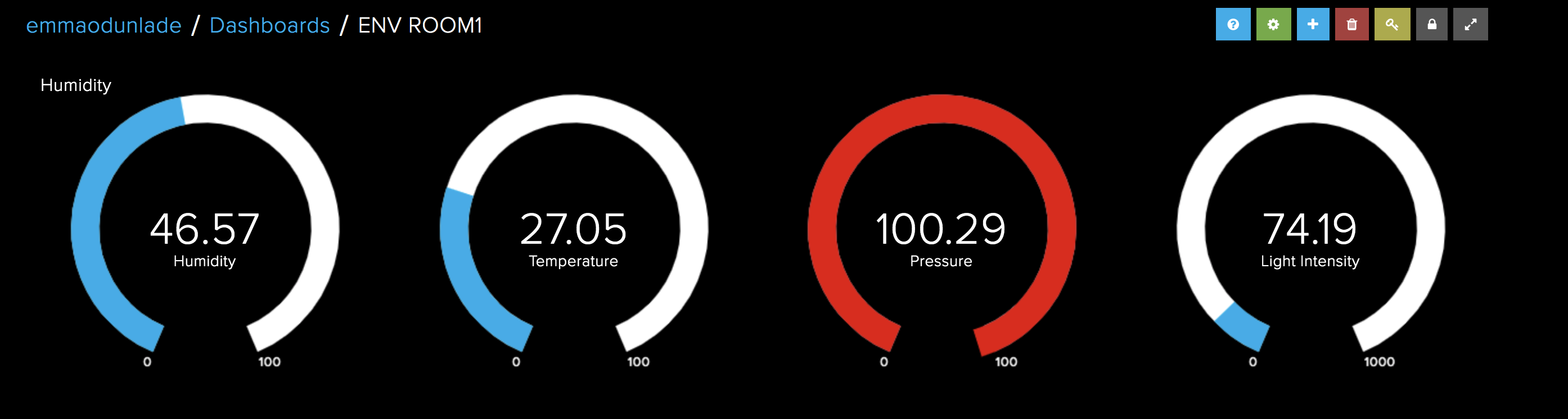
At this stage, we are ready to upload the code to the Arduino MKR WiFi 1010 board. Double check the connections between the Arduino and TFT LCD, and ensure the ENV shield is well plugged in. Also, check to ensure you have filled the credentials for the WiFi access point and your Adafruit IO account in the Arduino_secrets.h file. With this done, upload the code to the Arduino board. After a few minutes, you should see the data live on the Adafruit IO dashboard and the TFT display as shown in the image below.
Part 2 Demo
For the Part 2, Plug in the MKR RGB Shield into the MKR WiFi 1010 board as described under the schematics section and double check to ensure you have filled the credentials for the WiFi access point in the Arduino_Secrets.h file.
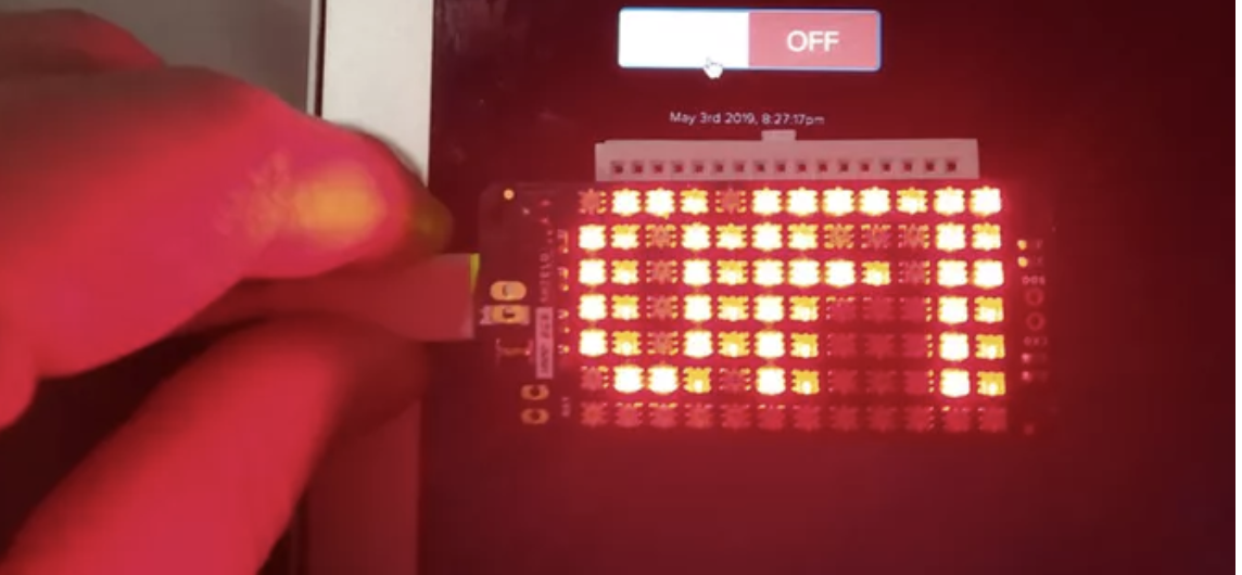
With everything in place, upload the code to the board and toggle the switch on the dashboard. You should see the text “on”/”off” being displayed on the RGB as you toggle the switch between “on” and “off”.
It is important to note that you can combine both sketches to build a system capable of two way communication with the IoT Cloud. We just separated things so as to be able to explain the steps in details. As a learning challenge, you can try combining the code for both parts or creating a similar project and test it out. That’s it for today’s tutorial, feel free to reach out to me via the comment section with questions and any general comment about today’s project.
Pictures Credits: AvilMaru