New and Improved Geiger Counter – Now With WiFi!
In one of our previous tutorials, we examined the development of a DIY-Geiger Counter showing the efforts of "Instructable" user Prabhat who combined the ESP8266 with a touch screen display to create a truly intuitive version of his Geiger Counter. He recently created an updated version and today's tutorial will focus on how this new version of the Geiger Counter can be replicated.
In one of our previous tutorials, we examined the development of a DIY-Geiger Counter showing the efforts of “Instructable” user Prabhat who combined the ESP8266 with a touch screen display to create a truly intuitive version of his Geiger Counter. He recently created an updated version and today’s tutorial will focus on how this new version of the Geiger Counter can be replicated.
The Geiger counter is an instrument used for detecting and measuring ionizing radiation. It is one of the worlds best-known radiation detection instrument as it can be used to detect ionizing radiation such as alpha particles, beta particles, and gamma rays and its is usually used as a handheld radiation survey instrument, warning users when in the region of dangerous ambient radiation levels with an all-too-familiar clicking noise.
While this project retains some of the features from the first version, like the use of the ESP8266 and a touchscreen interface, rather than just implementing the detection of radiation levels like the first version, it combines a Geiger counter, a dosimeter, and a radiation monitoring together in a single package that is 50% less thick, and with loads of new software features! Some of the new features include:
- A more intuitive GUI
- Displays counts per minute, current dose, and accumulated dose on the home screen
- Sensitive and reliable SBM-20 Geiger-Muller tube
- Variable integration time for averaging dose rate
- Timed count mode for measuring low doses
- Users can choose between Sieverts and Rems as the units for the displayed dose rate
- User-adjustable alert threshold
- Adjustable calibration to relate CPM to dose rate for various isotopes
- Offline data logging
- Post bulk-logged data to a cloud service (ThingSpeak) to graph, analyze and/or save to computer
- Monitoring Station mode: device stays connected to WiFi and regularly posts ambient radiation level to ThingSpeak channel
- 2000 mAh rechargeable LiPo battery with a 16 hour run time and a micro USB charging port
- No programming required from the end-user as things like the WiFi setup is handled through the user interface.
While most of these upgrades will not make sense to a non-radiation nerd, the updates take the device to a more powerful level when compared with some of the regular Geiger counter available in the market.
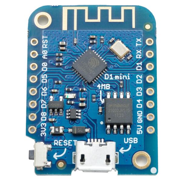
The ESP8266 was retained from the previous version, but a Wemos D1 mini was used in place of the NodeMCU to reduce the overall size of the project. The SBM-20 Geiger Muller tube and the 2.8″ SPI touchscreen were also retained. Several other discrete components were used with most of them being of SMD types to make the device compact.
At the end of this tutorial, you would know not only how to replicate this project but how to implement tasks like; building IoT Devices capable of uploading data to Thingspeak, update WiFi details using a GUI without changing the code and so many other fascinating things.
Required Components
The components required in making the full assembly of the project are provided in the list below. The list does not include the discrete components which will be provided in a table so things are not messy.
- WEMOS D1 Mini or clone
- 2.8″ SPI Touchscreen
- SBM-20 Geiger tube with it’s ends taken off (many vendors online)
- 3.7 V LiPo charger board
- Turnigy 3.7 V 1S 1C LiPo battery (49 x 34 x 10mm) with JST-PH connector
- M3 x 22 mm Countersunk screws
- M3 x 8 mm hex machine screws
- M3 brass threaded insert
- Conductive copper tape
SMB-20 Tube Electrical Specifications:
- Operating voltage: 350 to 475 V DC
- Minimum anode resistor: 1 MΩ (voltage rating at least 500 V)
- Recommended anode resistor: 5.1 MΩ (voltage rating at least 500 V)
- Plateau length: at least 100 V
- Plateau slope: 0.1% per 1 V
- Minimum dead time: 190 μs (at 400V)
SMB-20 Tube Physical specifications
- Diameter: 11 mm
- Length: 108 mm (+/- 2.5 mm)
- Weight: 10 g
- Temperature rating: -60 to +70°C
Other discrete components used are provided in the table below and the entire BOM is attached as a .CSV file under the download section.
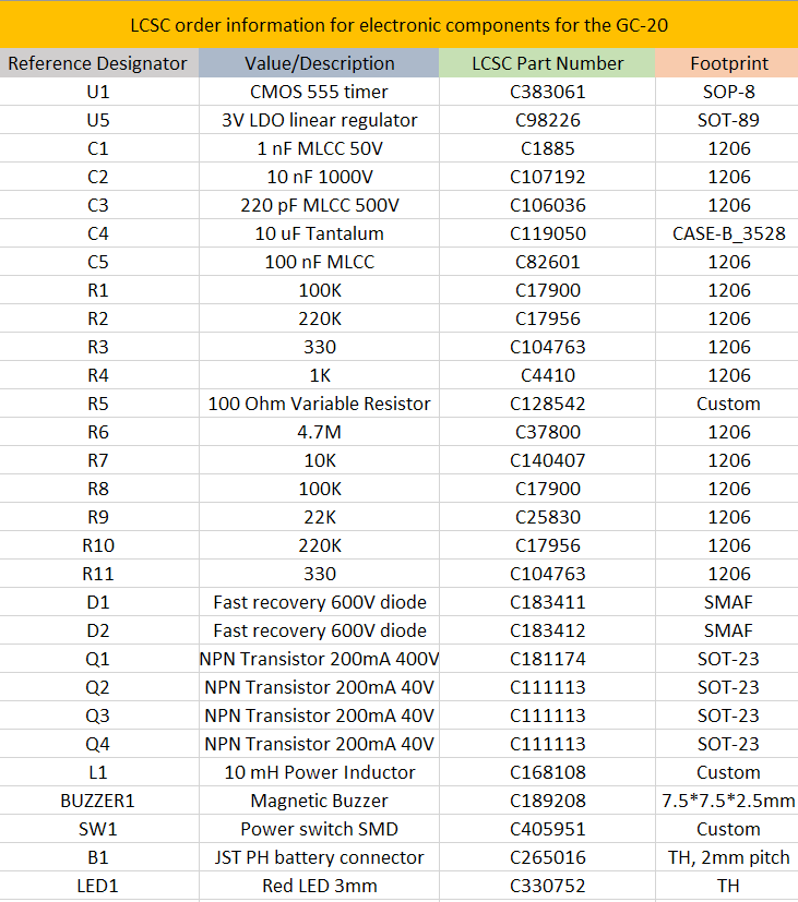
All discreet components used for the project were purchased from LCSC.com, so entering the part numbers in the LCSC search bar will show the exact components.
Schematics
The project was implemented using a PCB to make things compact and tidy. As mentioned earlier, most of the electronic parts used are SMD types, and this was done to reduce the size of the device as much as possible. The schematic for the project is designed by Prabhat and it is provided below:
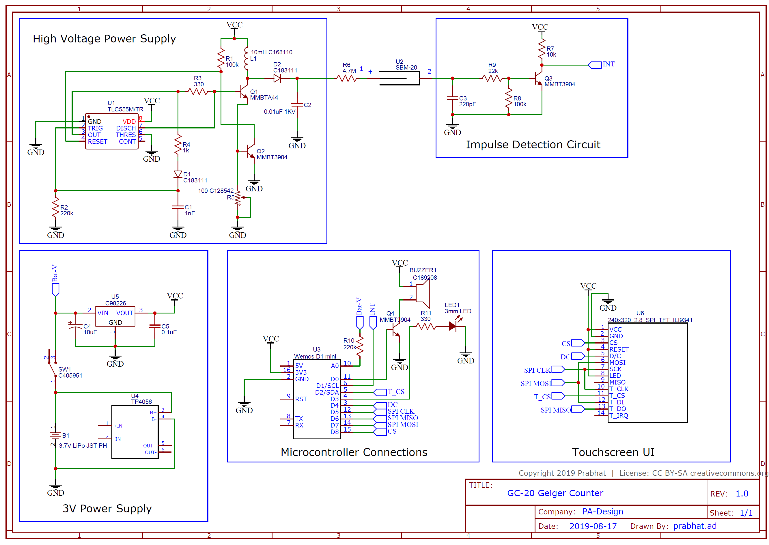
To make it easier for those who may want to make modifications or reproduce the PCB, all of the project files including the schematics and PCB which were developed using Kicad, have been included in the zip file under the download section and can also be downloaded from Prabhat’s GitHub page.
All passive components (resistors, capacitors) were implemented with a 1206 footprint, while the transistors were implemented with SOT-23, LDO in SOT-89, and 555 timers in SOIC-8. Custom footprints were made for the inductor, switch and the buzzer and the required files for them are also zipped with the other files under the download section.
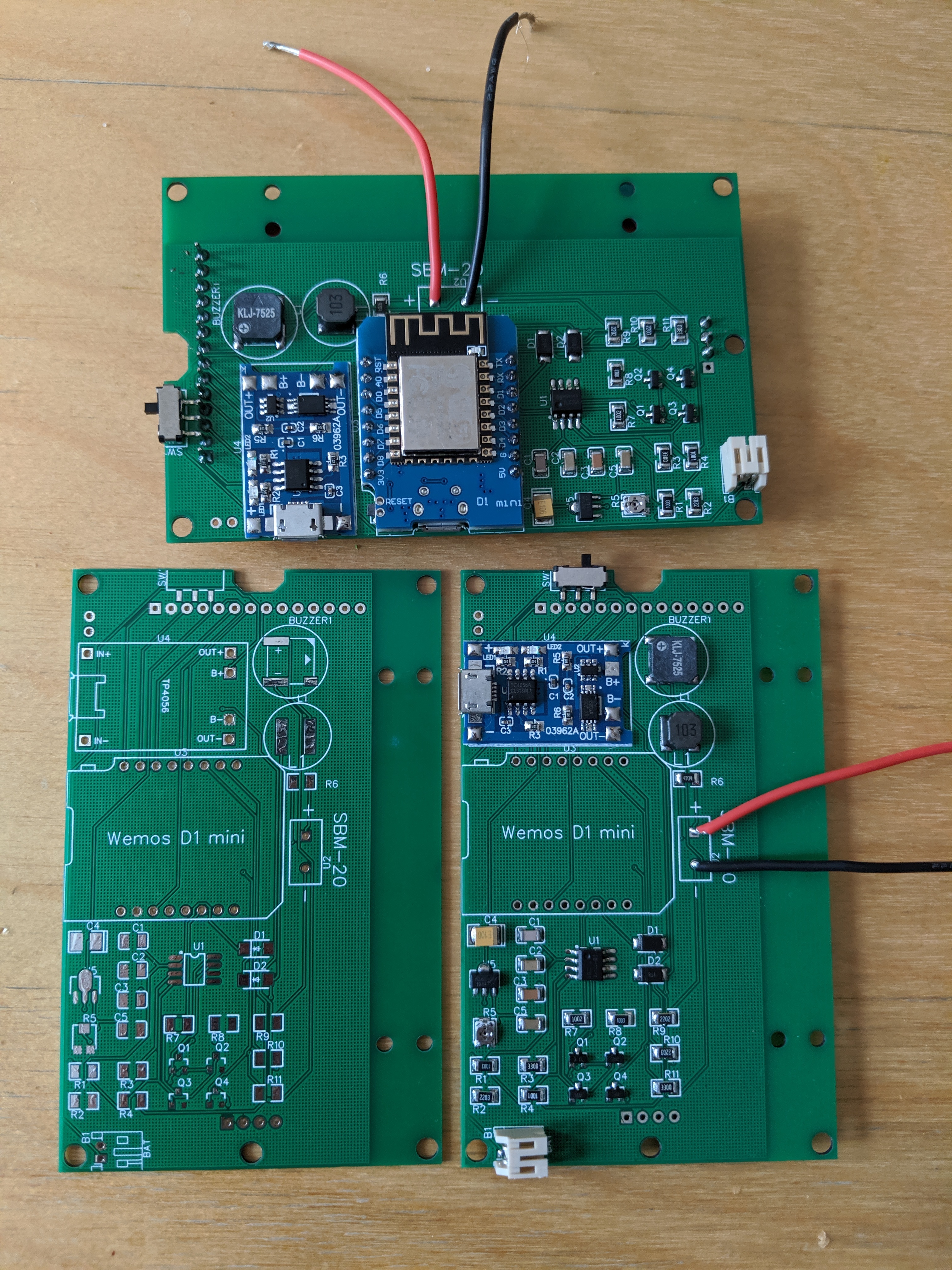
PCB
The PCB after fabrication will look like the image below;
Enclosure Design
A change in the design and placement of components between the two versions means we will also need to create another enclosure for today’s project.
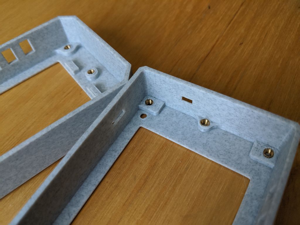
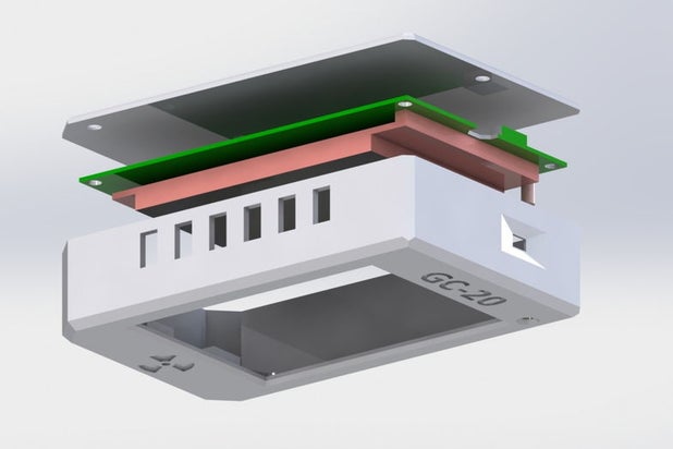
This enclosure was designed to match the new reduced size of the device. It contains fewer parts (just two) compared to the first version and screws are still used in its assembly. Rather than placing the Geiger Muller tube in the top part like the first version, it was placed on the sides of the enclosure to remove the need for additional space at the top of the device.
The .STL files of all parts of the enclosure are attached in the zip file under the download section.
Enclosure 3D View


Setup Thingspeak
As mentioned during the introduction, this version of the project will have the ability to operate in 3 modes, either as a Datalogger, Monitoring station or as the ordinary Geiger Counter. When used as a data logger or monitoring station, the device is sending it’s data to the cloud and for that reason, Thingspeak was used as the device cloud platform. As such, it is important to create a Thingspeak account and obtain all necessary credentials like; API key and Channel ID as they will be required when the project is being further developed.
Follow the steps below to set up your Thingspeak account;
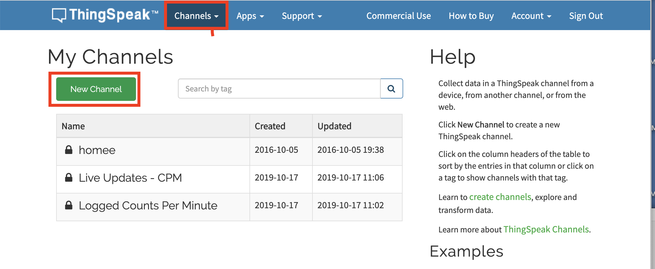
1. Go to Thingspeak and signup or sign-in if you already have an account.
2. After logging in, click on the channels button. This will lead you to the channels page. The channels page provides you with a list of all the channels you have created. Click on the add new channel button to add a new one.
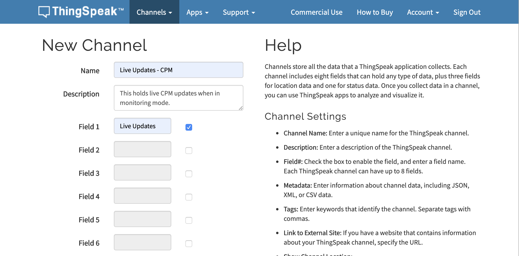
3. This will lead you to a page where you are expected to fill in the details of the channel. Enter the Name, a short description, and fields. For this project, we will create two channels. The first one will hold “Logged counts per minute” data with a field to hold the “CPM”.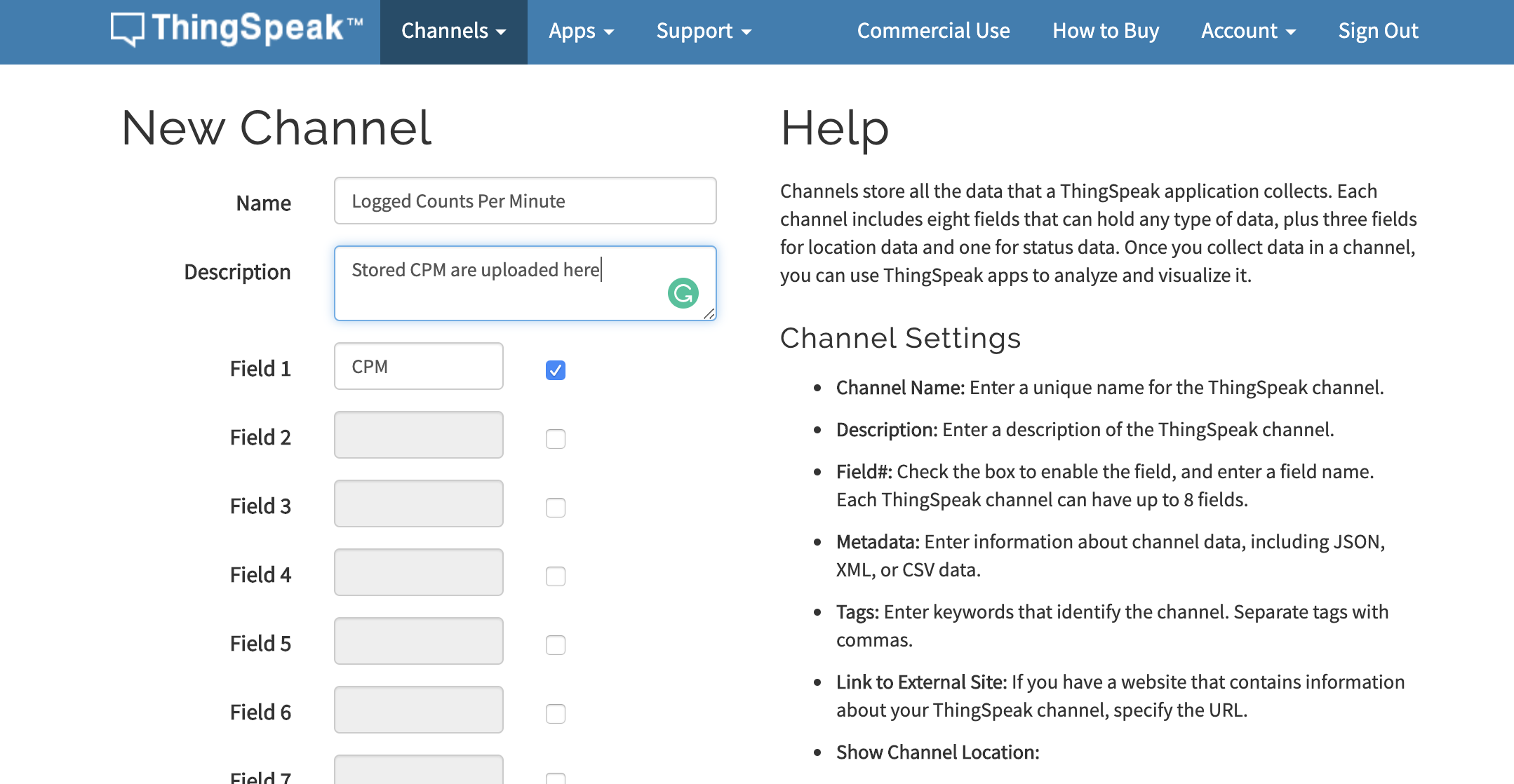
4. While the second one will hold “Live Updates of CPM” data with a field called “Live updates“. Click on the OK button after filling the details.
5. The two channels should now be added to your channel list like the image below.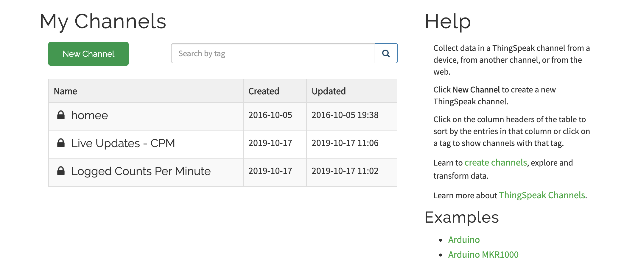
6. By clicking on each of the channels, you will be redirected to the dashboard for that channel where you will see it’s channel ID. Copy the channel ID for both channels as we will use them in our code.
7. On the channel dashboard, also click on API keys. This should show you the API keys to both read and write to the channel. Copy and keep the Write API key since our intention is to write to the channel.
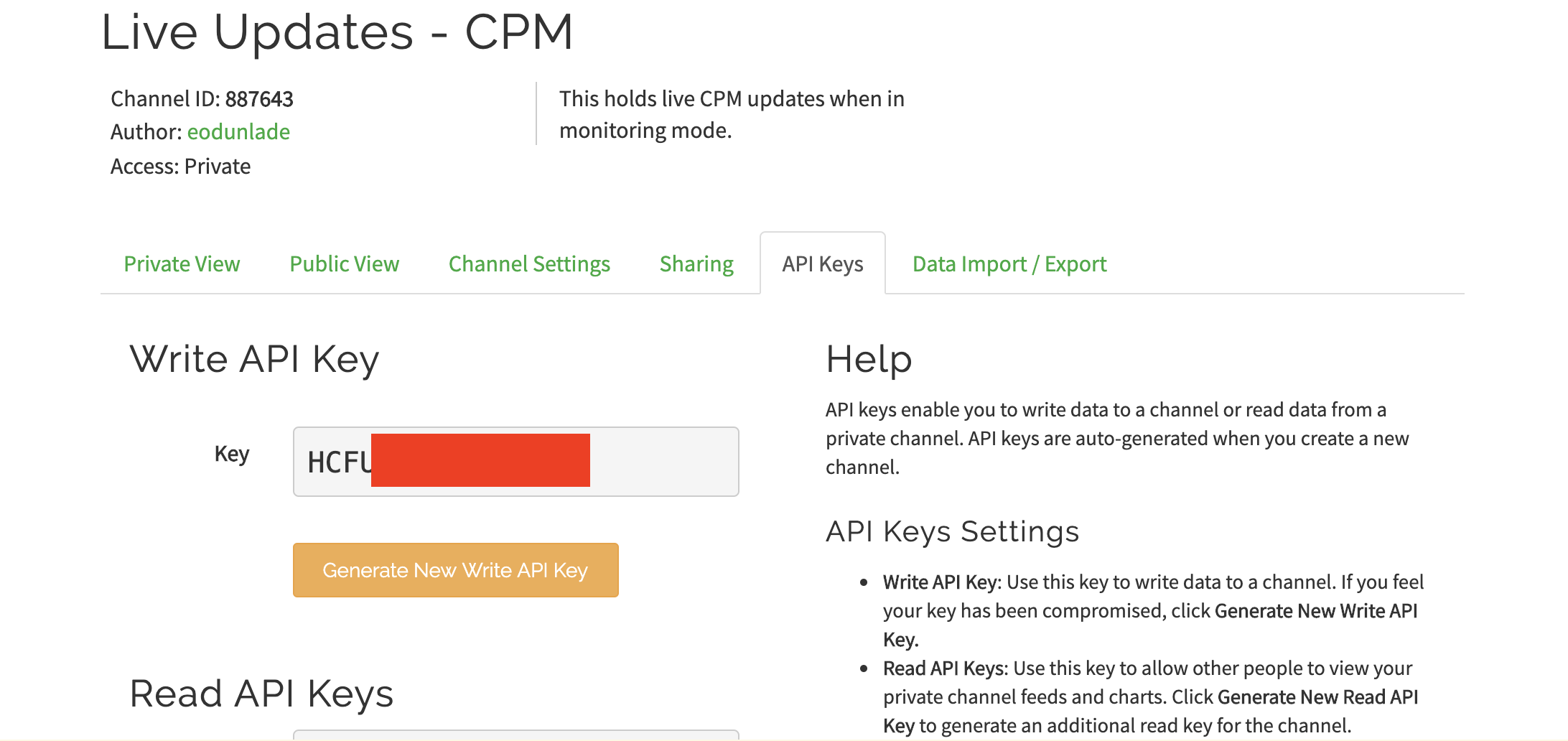
With this done we now have all we need to write the code.
Device Assembly
Follow the steps below to put the device together after the PCB has been assembled.
- Start by soldering all SMD components to the Main PCB first, using either a Hot Air Soldering station or reflow oven
- Also, Solder the battery charger board to the pads and the through-hole components to the main PCB.
- Remove the SD card reader from the LCD display to prevent it from interacting with the Process during data logging.
- Solder the LCD board to the PCB AT THE END. You won’t be able to de-solder the D1 Mini after this. Another option is to install the D1 mini using header pins, so there won’t be a need to solder it and it will be possible to remove it at will.
- Ensure there are no protruding LEDs and that all components were properly soldered.
- Take two pieces of stranded wire and solder one end of the first wire to one end (Anode) of the SBM-20, and connect one end of the second wire to the body of the SBM-2o holding it in place with copper tape. Connect the other end of the two wires to the anode and cathode connections (respectively) on the board. Take care to ensure the polarity is correct.
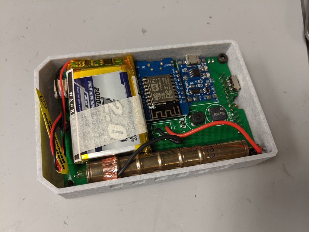
- 3D print the case and the cover, and arrange the components inside the case securing the assembled PCB with 3.8mm Screws. Also, place the Geiger tube beside the grill and tape it to prevent it from falling off. Connect all the wires, along with the battery and close up the enclosure using the cover. You should now be ready to go.
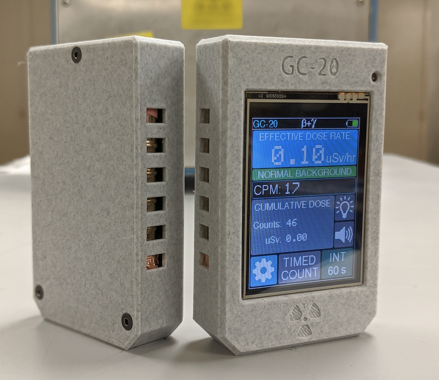
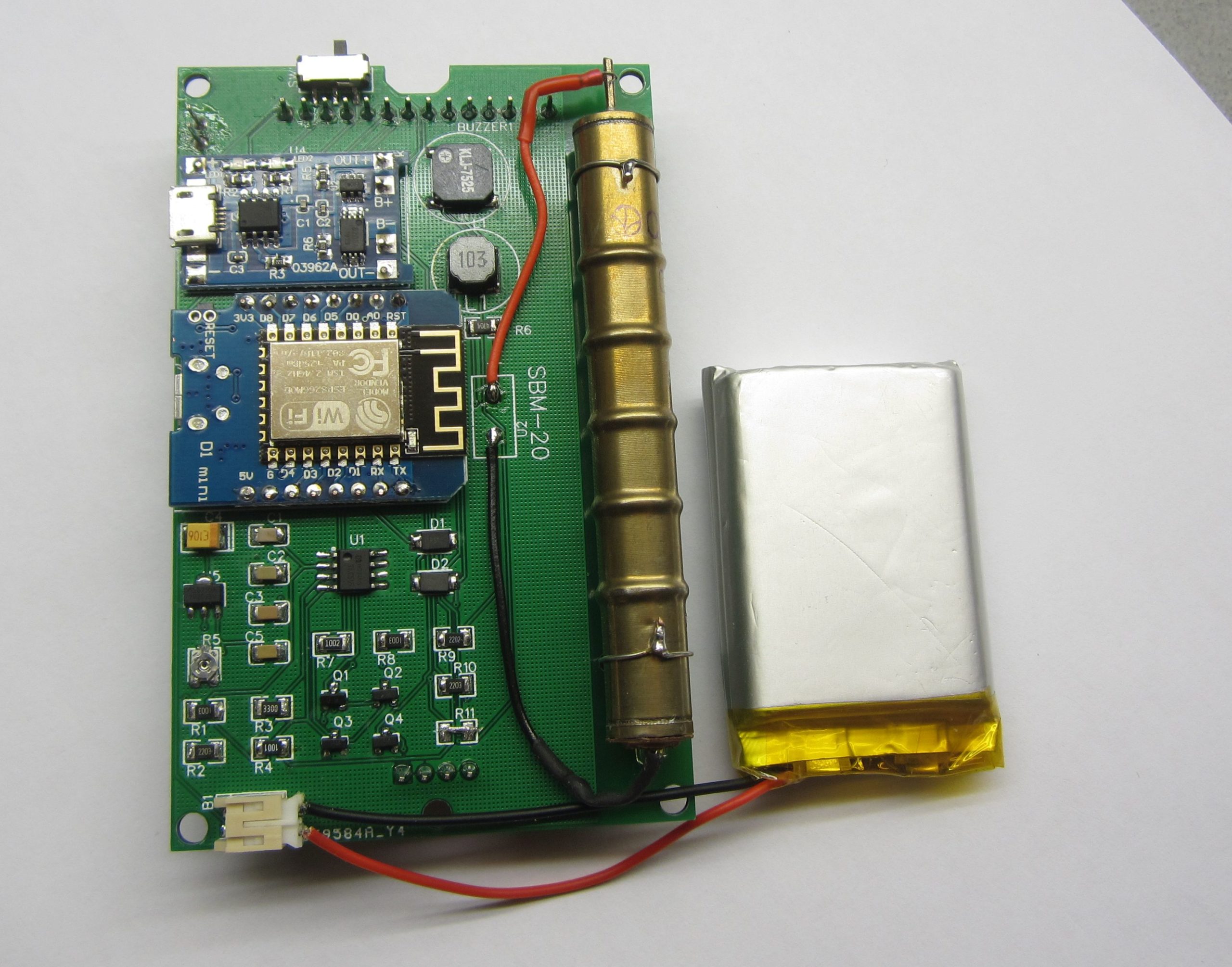
After assembling, the device should look like the image below before the back cover is mounted.
Code
Just like with the previous version, the code for this version is also developed using “PlatformIO IDE“. This means, if you didn’t go through the platformIO.org set up during the last tutorial, you have another chance to get it done now. Follow the tutorial we created a while back on how to Program the Arduino and ESP8266 Boards with Platform.io, to get it sorted.
The sketch for this project is heavily reliant on the Adafruit_ILI9341, the Adafruit GFX, the WiFi Manager library. The ILI9341 library allows us to directly interact with the display as it was used to create the user interface for the display, while the WiFi manager allows users to change the password stored on the device without making any changes to the code, removing the need to edit the code to add WiFi Credentials. Asides these libraries, we will use several other libraries like; the XPT2046_Touchscreen library, the EEPROM library, the SPI library among others. The XPT2046_touchscreen library allows us to use the touchscreen features of the display while the EEPROM library, on the other hand, allows us perform the same tasks it was used for in the first version; to save all the settings including WiFi credentials such that when power is recycled, the data is not lost and users won’t need to supply that information again. All of these libraries can be installed via the Arduino library manager.
The sketch is quite similar to the one for our last tutorial but as usual, I will do a quick explanation of some of the important parts of the code.
We start by declaring the libraries that will be used. In addition to the libraries mentioned above, we will add a couple of font libraries for use in displaying text on the display.
#include <Arduino.h>
#include <ESP8266WiFi.h>
#include <EthernetClient.h>
#include <DNSServer.h>
#include <ESP8266WebServer.h>
#include <WifiManager.h>
#include <EEPROM.h>
#include "SPI.h"
#include "Adafruit_GFX.h"
#include <Fonts/FreeSans9pt7b.h>
#include <Fonts/FreeSans12pt7b.h>
#include "Adafruit_ILI9341.h"
#include <XPT2046_Touchscreen.h>
Next, we create an object of the touchscreen library with the CS pin as an argument and then create variables to hold the (4 extremes) calibration points for the touch screen and specify the pins of the Arduino to which the DC and CS pins of the display are connected.
#define CS_PIN D2
XPT2046_Touchscreen ts(CS_PIN);

#define TS_MINX 250
#define TS_MINY 200 // calibration points for touchscreen
#define TS_MAXX 3800
#define TS_MAXY 3750

#define TFT_DC D4
#define TFT_CS D8
We also create variables to hold the hex values signifying the different colors that we will be using after which we create variables to hold various WiFi/data upload parameters like the password, SSID, API key and channel ID as obtained from Thingspeak, Thingspeak server address among others.
#define BLACK 0x0000
#define BLUE 0x001F
#define RED 0xF800
#define GREEN 0x07E0
#define CYAN 0x07FF
#define MAGENTA 0xF81F
#define YELLOW 0xFFE0
#define WHITE 0xFFFF
#define DOSEBACKGROUND 0x0455

// WiFi variables
unsigned long currentUploadTime;
unsigned long previousUploadTime;
int passwordLength;
int SSIDLength;
int channelIDLength;
int writeAPILength;
char ssid[20];
char password[20];
char channelID[20]; // = "864288";
char channelAPIkey[20]; // = "37SAHQPEQ7FOBC20";
char server[] = "api.thingspeak.com";
int attempts; // number of connection attempts when device starts up in monitoring mode
Next, we create a WiFi through which the device will communicate over the web, and we create an instance of the Adafruit TFT library.
WiFiClient client;

Adafruit_ILI9341 tft = Adafruit_ILI9341(TFT_CS, TFT_DC);
Other variables that will be used for data logging on Thingspeak, monitoring the battery, saving data in the EEPROM, and calculating the dosing units are then created.
const int interruptPin = 5;

long count[61];
long fastCount[6]; // arrays to store running counts
long slowCount[181];
int i = 0;         // array elements
int j = 0;
int k = 0;

int page = 0;

long currentMillis;
long previousMillis;
unsigned long currentMicros;
unsigned long previousMicros;

unsigned long averageCount;
unsigned long currentCount;  // incremented by interrupt
unsigned long previousCount; // to activate buzzer and LED
unsigned long cumulativeCount;
float doseRate;
float totalDose;
char dose[5];
int doseLevel;               // determines home screen warning signs
int previousDoseLevel;

bool ledSwitch = 1;
bool buzzerSwitch = 1;
bool wasTouched;
int integrationMode = 0; // 0 = medium, 1 = fast, 2 == slow;

bool doseUnits = 0; // 0 = Sievert, 1 = Rem
unsigned int alarmThreshold = 5;
unsigned int conversionFactor = 175;

int x, y; // touch points

// Battery indicator variables
int batteryInput;
int batteryPercent;
int batteryMapped = 212;       // pixel location of battery icon
int batteryUpdateCounter = 29;

// EEPROM variables
const int saveUnits = 0;
const int saveAlertThreshold = 1; // Addresses for storing settings data in the EEPROM
const int saveCalibration = 2;
const int saveDeviceMode = 3;
const int saveLoggingMode = 4;
const int saveSSIDLen = 5;
const int savePWLen = 6;
const int saveIDLen = 7;
const int saveAPILen = 8;

// Data Logging variables
int addr = 200;                 // starting address for data logging
char jsonBuffer[14000] = "[";
char data[14500] = "{\"write_api_key\":\"";
unsigned long currentLogTime;
unsigned long previousLogTime;


// Timed Count Variables:
int interval = 5;
unsigned long intervalMillis;
unsigned long startMillis;
unsigned long elapsedTime;
int progress;
float cpm;
bool completed = 0;
int intervalSize; // stores how many digits are in the interval

// Logging variables
bool isLogging;

bool deviceMode;

// interrupt routine declaration
void ICACHE_RAM_ATTR isr();

unsigned int previousIntMicros;              // timers to limit count increment rate in the ISR
Next, we create variables that are used to hold the Char equivalent of different bitmap images. We covered how to generate this in a previous tutorial we did on displaying bitmap images on LCDs.
const unsigned char gammaBitmap [] PROGMEM = {
  0x30, 0x00, 0x78, 0x70, 0xe8, 0xe0, 0xc4, 0xe0, 0x84, 0xc0, 0x05, 0xc0, 0x05, 0x80, 0x07, 0x80,
  0x03, 0x00, 0x07, 0x00, 0x0e, 0x00, 0x0e, 0x00, 0x1e, 0x00, 0x1e, 0x00, 0x1e, 0x00, 0x3e, 0x00,
  0x1c, 0x00, 0x00, 0x00
};

const unsigned char betaBitmap [] PROGMEM = {
  0x00, 0xc0, 0x00, 0x03, 0xf0, 0x00, 0x07, 0x18, 0x00, 0x06, 0x18, 0x00, 0x0e, 0x18, 0x00, 0x0e,
  0x18, 0x00, 0x0e, 0xf8, 0x00, 0x0e, 0x1c, 0x00, 0x0e, 0x0c, 0x00, 0x0e, 0x0c, 0x00, 0x0e, 0x0c,
  0x00, 0x0e, 0x0c, 0x00, 0x0f, 0x1c, 0x00, 0x0f, 0xf8, 0x00, 0x0e, 0x00, 0x00, 0x0e, 0x00, 0x00,
  0x0c, 0x00, 0x00, 0x00, 0x00, 0x00
};
const unsigned char wifiBitmap [] PROGMEM = {
  0x00, 0x00, 0x00, 0x00, 0x00, 0x00, 0x01, 0xf0, 0x00, 0x0f, 0xfe, 0x00, 0x3f, 0xff, 0x80, 0x78,
  0x03, 0xc0, 0xe0, 0x00, 0xe0, 0x47, 0xfc, 0x40, 0x0f, 0xfe, 0x00, 0x1c, 0x07, 0x00, 0x08, 0x02,
  0x00, 0x01, 0xf0, 0x00, 0x03, 0xf8, 0x00, 0x01, 0x10, 0x00, 0x00, 0x40, 0x00, 0x00, 0xe0, 0x00,
  0x00, 0x40, 0x00, 0x00, 0x00, 0x00, 0x00, 0x00, 0x00
};

const unsigned char settingsBitmap[] PROGMEM = {
    0x00, 0x00, 0x00, 0x00, 0x00, 0x00, 0x00, 0x00, 0x00, 0x00, 0x00, 0x00, 0x00, 0x00, 0x00, 0x00,
    0x00, 0x00, 0x00, 0x00, 0x00, 0x00, 0x00, 0x00, 0x00, 0x00, 0x00, 0x00, 0x00, 0x00, 0x00, 0x00,
    0x00, 0x00, 0x00, 0x00, 0x00, 0x00, 0x00, 0x00, 0x00, 0x00, 0x00, 0x00, 0x00, 0x00, 0x00, 0x00,
    0x00, 0x00, 0x00, 0x00, 0x00, 0x00, 0x00, 0x00, 0x00, 0x00, 0x00, 0x1f, 0x80, 0x00, 0x00, 0x00,
    0x00, 0x00, 0x00, 0x3f, 0xc0, 0x00, 0x00, 0x00, 0x00, 0x00, 0x00, 0x3f, 0xc0, 0x00, 0x00, 0x00,
    0x00, 0x00, 0x00, 0x3f, 0xc0, 0x00, 0x00, 0x00, 0x00, 0x00, 0x00, 0x7f, 0xe0, 0x00, 0x00, 0x00,
    0x00, 0x01, 0xc0, 0x7f, 0xe0, 0x38, 0x00, 0x00, 0x00, 0x03, 0xf0, 0x7f, 0xe0, 0xfc, 0x00, 0x00,
    0x00, 0x07, 0xf9, 0xff, 0xf9, 0xfe, 0x00, 0x00, 0x00, 0x0f, 0xff, 0xff, 0xff, 0xff, 0x00, 0x00,
    0x00, 0x0f, 0xff, 0xff, 0xff, 0xff, 0x00, 0x00, 0x00, 0x0f, 0xff, 0xff, 0xff, 0xff, 0x00, 0x00,
    0x00, 0x07, 0xff, 0xff, 0xff, 0xfe, 0x00, 0x00, 0x00, 0x07, 0xff, 0xff, 0xff, 0xfe, 0x00, 0x00,
    0x00, 0x03, 0xff, 0xff, 0xff, 0xfc, 0x00, 0x00, 0x00, 0x01, 0xff, 0xff, 0xff, 0xf8, 0x00, 0x00,
    0x00, 0x01, 0xff, 0xff, 0xff, 0xf8, 0x00, 0x00, 0x00, 0x03, 0xff, 0xf0, 0x7f, 0xfc, 0x00, 0x00,
    0x00, 0x03, 0xff, 0xc0, 0x3f, 0xfc, 0x00, 0x00, 0x00, 0x1f, 0xff, 0x80, 0x1f, 0xff, 0x80, 0x00,
    0x00, 0xff, 0xff, 0x00, 0x0f, 0xff, 0xf0, 0x00, 0x01, 0xff, 0xff, 0x00, 0x07, 0xff, 0xf8, 0x00,
    0x01, 0xff, 0xfe, 0x00, 0x07, 0xff, 0xf8, 0x00, 0x01, 0xff, 0xfe, 0x00, 0x07, 0xff, 0xf8, 0x00,
    0x01, 0xff, 0xfe, 0x00, 0x07, 0xff, 0xf8, 0x00, 0x01, 0xff, 0xfe, 0x00, 0x07, 0xff, 0xf8, 0x00,
    0x01, 0xff, 0xfe, 0x00, 0x07, 0xff, 0xf8, 0x00, 0x00, 0xff, 0xff, 0x00, 0x0f, 0xff, 0xf0, 0x00,
    0x00, 0x1f, 0xff, 0x80, 0x1f, 0xff, 0x80, 0x00, 0x00, 0x03, 0xff, 0xc0, 0x3f, 0xfc, 0x00, 0x00,
    0x00, 0x03, 0xff, 0xe0, 0x7f, 0xfc, 0x00, 0x00, 0x00, 0x01, 0xff, 0xff, 0xff, 0xf8, 0x00, 0x00,
    0x00, 0x01, 0xff, 0xff, 0xff, 0xf8, 0x00, 0x00, 0x00, 0x03, 0xff, 0xff, 0xff, 0xfc, 0x00, 0x00,
    0x00, 0x07, 0xff, 0xff, 0xff, 0xfe, 0x00, 0x00, 0x00, 0x07, 0xff, 0xff, 0xff, 0xfe, 0x00, 0x00,
    0x00, 0x0f, 0xff, 0xff, 0xff, 0xff, 0x00, 0x00, 0x00, 0x0f, 0xff, 0xff, 0xff, 0xff, 0x00, 0x00,
    0x00, 0x0f, 0xff, 0xff, 0xff, 0xff, 0x00, 0x00, 0x00, 0x07, 0xf9, 0xff, 0xf9, 0xfe, 0x00, 0x00,
    0x00, 0x03, 0xf0, 0x7f, 0xe0, 0xfc, 0x00, 0x00, 0x00, 0x01, 0xc0, 0x7f, 0xe0, 0x38, 0x00, 0x00,
    0x00, 0x00, 0x00, 0x7f, 0xe0, 0x00, 0x00, 0x00, 0x00, 0x00, 0x00, 0x3f, 0xc0, 0x00, 0x00, 0x00,
    0x00, 0x00, 0x00, 0x3f, 0xc0, 0x00, 0x00, 0x00, 0x00, 0x00, 0x00, 0x3f, 0xc0, 0x00, 0x00, 0x00,
    0x00, 0x00, 0x00, 0x1f, 0x80, 0x00, 0x00, 0x00, 0x00, 0x00, 0x00, 0x00, 0x00, 0x00, 0x00, 0x00,
    0x00, 0x00, 0x00, 0x00, 0x00, 0x00, 0x00, 0x00, 0x00, 0x00, 0x00, 0x00, 0x00, 0x00, 0x00, 0x00,
    0x00, 0x00, 0x00, 0x00, 0x00, 0x00, 0x00, 0x00, 0x00, 0x00, 0x00, 0x00, 0x00, 0x00, 0x00, 0x00,
    0x00, 0x00, 0x00, 0x00, 0x00, 0x00, 0x00, 0x00, 0x00, 0x00, 0x00, 0x00, 0x00, 0x00, 0x00, 0x00};

const unsigned char buzzerOnBitmap[] PROGMEM = {
    0x00, 0x00, 0x00, 0x00, 0x00, 0x00, 0x00, 0x00, 0x00, 0x00, 0x00, 0x00, 0x00, 0x00, 0x00, 0x00,
    0x00, 0x00, 0x00, 0x00, 0x00, 0x00, 0x00, 0x00, 0x00, 0x00, 0x00, 0x00, 0x00, 0x00, 0x00, 0x00,
    0x00, 0x00, 0x00, 0x00, 0x00, 0x00, 0x00, 0x00, 0x00, 0x00, 0x00, 0x00, 0x03, 0x80, 0x0c, 0x00,
    0x00, 0x00, 0x07, 0x80, 0x0e, 0x00, 0x00, 0x00, 0x0f, 0x80, 0x0f, 0x00, 0x00, 0x00, 0x1f, 0x80,
    0x07, 0x00, 0x00, 0x00, 0x3f, 0x80, 0xc7, 0x80, 0x00, 0x00, 0xff, 0x80, 0xe3, 0x80, 0x00, 0x01,
    0xff, 0x80, 0xf3, 0xc0, 0x00, 0x03, 0xff, 0x80, 0x71, 0xc0, 0x00, 0x07, 0xff, 0x8c, 0x79, 0xc0,
    0x3f, 0xff, 0xff, 0x9e, 0x38, 0xe0, 0x3f, 0xff, 0xff, 0x8e, 0x38, 0xe0, 0x3f, 0xff, 0xff, 0x8e,
    0x3c, 0xe0, 0x3f, 0xff, 0xff, 0x87, 0x1c, 0xe0, 0x3f, 0xff, 0xff, 0x87, 0x1c, 0x60, 0x3f, 0xff,
    0xff, 0x87, 0x1c, 0x70, 0x3f, 0xff, 0xff, 0x87, 0x1c, 0x70, 0x3f, 0xff, 0xff, 0x87, 0x1c, 0x70,
    0x3f, 0xff, 0xff, 0x87, 0x1c, 0x70, 0x3f, 0xff, 0xff, 0x87, 0x1c, 0x70, 0x3f, 0xff, 0xff, 0x87,
    0x1c, 0xe0, 0x3f, 0xff, 0xff, 0x8e, 0x3c, 0xe0, 0x3f, 0xff, 0xff, 0x8e, 0x38, 0xe0, 0x3f, 0xff,
    0xff, 0x9e, 0x38, 0xe0, 0x00, 0x07, 0xff, 0x8c, 0x79, 0xc0, 0x00, 0x03, 0xff, 0x80, 0x71, 0xc0,
    0x00, 0x00, 0xff, 0x80, 0xf1, 0xc0, 0x00, 0x00, 0x7f, 0x80, 0xe3, 0x80, 0x00, 0x00, 0x3f, 0x80,
    0xc7, 0x80, 0x00, 0x00, 0x1f, 0x80, 0x07, 0x00, 0x00, 0x00, 0x0f, 0x80, 0x0f, 0x00, 0x00, 0x00,
    0x07, 0x80, 0x0e, 0x00, 0x00, 0x00, 0x03, 0x80, 0x0c, 0x00, 0x00, 0x00, 0x00, 0x00, 0x00, 0x00,
    0x00, 0x00, 0x00, 0x00, 0x00, 0x00, 0x00, 0x00, 0x00, 0x00, 0x00, 0x00, 0x00, 0x00, 0x00, 0x00,
    0x00, 0x00, 0x00, 0x00, 0x00, 0x00, 0x00, 0x00, 0x00, 0x00, 0x00, 0x00, 0x00, 0x00};

const unsigned char buzzerOffBitmap[] PROGMEM = {
    0x00, 0x00, 0x00, 0x00, 0x00, 0x00, 0x00, 0x00, 0x00, 0x00, 0x00, 0x00, 0x00, 0x00, 0x03, 0x80,
    0x00, 0x00, 0x00, 0x00, 0x0f, 0x80, 0x00, 0x00, 0x00, 0x00, 0x1f, 0x80, 0x00, 0x00, 0x00, 0x00,
    0x3f, 0x80, 0x00, 0x00, 0x00, 0x00, 0x7f, 0x80, 0x00, 0x00, 0x00, 0x00, 0xff, 0x80, 0x00, 0x00,
    0x00, 0x03, 0xff, 0x80, 0x00, 0x00, 0x00, 0x07, 0xff, 0x80, 0x00, 0x00, 0x00, 0x0f, 0xff, 0x80,
    0x00, 0x00, 0x0f, 0xff, 0xff, 0x80, 0x00, 0x00, 0x1f, 0xff, 0xff, 0x80, 0x00, 0x00, 0x3f, 0xff,
    0xff, 0x8f, 0x00, 0x78, 0x7f, 0xff, 0xff, 0x8f, 0x80, 0xf8, 0x7f, 0xff, 0xff, 0x8f, 0xc1, 0xf8,
    0x7f, 0xff, 0xff, 0x87, 0xe3, 0xf0, 0x7f, 0xff, 0xff, 0x83, 0xf7, 0xe0, 0x7f, 0xff, 0xff, 0x81,
    0xff, 0xc0, 0x7f, 0xff, 0xff, 0x80, 0xff, 0x80, 0x7f, 0xff, 0xff, 0x80, 0x7f, 0x00, 0x7f, 0xff,
    0xff, 0x80, 0x7f, 0x00, 0x7f, 0xff, 0xff, 0x80, 0xff, 0x80, 0x7f, 0xff, 0xff, 0x81, 0xff, 0xc0,
    0x7f, 0xff, 0xff, 0x83, 0xf7, 0xe0, 0x7f, 0xff, 0xff, 0x87, 0xe3, 0xf0, 0x7f, 0xff, 0xff, 0x8f,
    0xc1, 0xf0, 0x7f, 0xff, 0xff, 0x8f, 0x80, 0xf8, 0x3f, 0xff, 0xff, 0x8f, 0x00, 0x70, 0x3f, 0xff,
    0xff, 0x84, 0x00, 0x20, 0x1f, 0xff, 0xff, 0x80, 0x00, 0x00, 0x0f, 0xff, 0xff, 0x80, 0x00, 0x00,
    0x00, 0x07, 0xff, 0x80, 0x00, 0x00, 0x00, 0x03, 0xff, 0x80, 0x00, 0x00, 0x00, 0x01, 0xff, 0x80,
    0x00, 0x00, 0x00, 0x00, 0xff, 0x80, 0x00, 0x00, 0x00, 0x00, 0x7f, 0x80, 0x00, 0x00, 0x00, 0x00,
    0x1f, 0x80, 0x00, 0x00, 0x00, 0x00, 0x0f, 0x80, 0x00, 0x00, 0x00, 0x00, 0x07, 0x80, 0x00, 0x00,
    0x00, 0x00, 0x03, 0x80, 0x00, 0x00, 0x00, 0x00, 0x00, 0x00, 0x00, 0x00, 0x00, 0x00, 0x00, 0x00,
    0x00, 0x00, 0x00, 0x00, 0x00, 0x00, 0x00, 0x00, 0x00, 0x00, 0x00, 0x00, 0x00, 0x00};

const unsigned char ledOnBitmap[] PROGMEM = {
    0x00, 0x00, 0x02, 0x00, 0x00, 0x00, 0x00, 0x00, 0x07, 0x00, 0x00, 0x00, 0x00, 0x00, 0x07, 0x00,
    0x00, 0x00, 0x00, 0x18, 0x07, 0x00, 0xc0, 0x00, 0x00, 0x1c, 0x07, 0x01, 0xc0, 0x00, 0x00, 0x1e,
    0x07, 0x03, 0xc0, 0x00, 0x00, 0x0e, 0x07, 0x03, 0x80, 0x00, 0x00, 0x0f, 0x00, 0x07, 0x80, 0x00,
    0x00, 0x07, 0x00, 0x07, 0x00, 0x00, 0x00, 0x00, 0x00, 0x00, 0x00, 0x00, 0x00, 0x00, 0x00, 0x00,
    0x00, 0x00, 0x1e, 0x00, 0x1f, 0xc0, 0x03, 0xc0, 0x0f, 0x80, 0x7f, 0xf0, 0x0f, 0x80, 0x07, 0xc1,
    0xff, 0xfc, 0x1f, 0x00, 0x03, 0xc3, 0xe0, 0x3e, 0x1e, 0x00, 0x00, 0x07, 0xc0, 0x0f, 0x00, 0x00,
    0x00, 0x07, 0x00, 0x07, 0x00, 0x00, 0x00, 0x0f, 0x00, 0x07, 0x80, 0x00, 0x00, 0x0e, 0x00, 0x03,
    0x80, 0x00, 0x00, 0x0e, 0x00, 0x03, 0x80, 0x00, 0x00, 0x1c, 0x00, 0x01, 0xc0, 0x00, 0x7f, 0x1c,
    0x00, 0x01, 0xc3, 0xf0, 0x7f, 0x1c, 0x00, 0x01, 0xc7, 0xf0, 0x3c, 0x0e, 0x00, 0x03, 0x81, 0xe0,
    0x00, 0x0e, 0x00, 0x03, 0x80, 0x00, 0x00, 0x0e, 0x00, 0x03, 0x80, 0x00, 0x00, 0x0f, 0x00, 0x07,
    0x80, 0x00, 0x00, 0x07, 0x00, 0x07, 0x00, 0x00, 0x00, 0x07, 0x80, 0x0f, 0x00, 0x00, 0x01, 0xc3,
    0xc0, 0x1e, 0x1c, 0x00, 0x07, 0xc1, 0xc0, 0x1c, 0x1f, 0x00, 0x0f, 0x81, 0xe0, 0x3c, 0x0f, 0x80,
    0x1e, 0x00, 0xe0, 0x38, 0x03, 0xc0, 0x0c, 0x00, 0xe0, 0x38, 0x01, 0x80, 0x00, 0x00, 0xf0, 0x78,
    0x00, 0x00, 0x00, 0x00, 0x7f, 0xf0, 0x00, 0x00, 0x00, 0x00, 0x7f, 0xf0, 0x00, 0x00, 0x00, 0x00,
    0x3f, 0xe0, 0x00, 0x00, 0x00, 0x00, 0x3f, 0xe0, 0x00, 0x00, 0x00, 0x00, 0x3f, 0xe0, 0x00, 0x00,
    0x00, 0x00, 0x3f, 0xe0, 0x00, 0x00, 0x00, 0x00, 0x3f, 0xe0, 0x00, 0x00, 0x00, 0x00, 0x3f, 0xe0,
    0x00, 0x00, 0x00, 0x00, 0x1f, 0xc0, 0x00, 0x00, 0x00, 0x00, 0x07, 0x00, 0x00, 0x00};

const unsigned char ledOffBitmap[] PROGMEM = {
    0x00, 0x00, 0x00, 0x00, 0x00, 0x00, 0x00, 0x00, 0x00, 0x00, 0x00, 0x00, 0x00, 0x00, 0x00, 0x00,
    0x00, 0x00, 0x00, 0x00, 0x00, 0x00, 0x00, 0x00, 0x00, 0x00, 0x00, 0x00, 0x00, 0x00, 0x00, 0x00,
    0x00, 0x00, 0x00, 0x00, 0x00, 0x00, 0x00, 0x00, 0x00, 0x00, 0x00, 0x00, 0x00, 0x00, 0x00, 0x00,
    0x00, 0x00, 0x00, 0x00, 0x00, 0x00, 0x00, 0x00, 0x00, 0x00, 0x00, 0x00, 0x00, 0x00, 0x00, 0x00,
    0x00, 0x00, 0x00, 0x00, 0x1f, 0xc0, 0x00, 0x00, 0x00, 0x00, 0x7f, 0xf0, 0x00, 0x00, 0x00, 0x01,
    0xff, 0xfc, 0x00, 0x00, 0x00, 0x03, 0xe0, 0x3e, 0x00, 0x00, 0x00, 0x07, 0xc0, 0x0f, 0x00, 0x00,
    0x00, 0x07, 0x00, 0x07, 0x00, 0x00, 0x00, 0x0f, 0x00, 0x07, 0x80, 0x00, 0x00, 0x0e, 0x00, 0x03,
    0x80, 0x00, 0x00, 0x0e, 0x00, 0x03, 0x80, 0x00, 0x00, 0x1c, 0x00, 0x01, 0xc0, 0x00, 0x00, 0x1c,
    0x00, 0x01, 0xc0, 0x00, 0x00, 0x1c, 0x00, 0x01, 0xc0, 0x00, 0x00, 0x0e, 0x00, 0x03, 0x80, 0x00,
    0x00, 0x0e, 0x00, 0x03, 0x80, 0x00, 0x00, 0x0e, 0x00, 0x03, 0x80, 0x00, 0x00, 0x0f, 0x00, 0x07,
    0x80, 0x00, 0x00, 0x07, 0x00, 0x07, 0x00, 0x00, 0x00, 0x07, 0x80, 0x0f, 0x00, 0x00, 0x00, 0x03,
    0xc0, 0x1e, 0x00, 0x00, 0x00, 0x01, 0xc0, 0x1c, 0x00, 0x00, 0x00, 0x01, 0xe0, 0x3c, 0x00, 0x00,
    0x00, 0x00, 0xe0, 0x38, 0x00, 0x00, 0x00, 0x00, 0xe0, 0x38, 0x00, 0x00, 0x00, 0x00, 0xf0, 0x78,
    0x00, 0x00, 0x00, 0x00, 0x7f, 0xf0, 0x00, 0x00, 0x00, 0x00, 0x7f, 0xf0, 0x00, 0x00, 0x00, 0x00,
    0x3f, 0xe0, 0x00, 0x00, 0x00, 0x00, 0x3f, 0xe0, 0x00, 0x00, 0x00, 0x00, 0x3f, 0xe0, 0x00, 0x00,
    0x00, 0x00, 0x3f, 0xe0, 0x00, 0x00, 0x00, 0x00, 0x3f, 0xe0, 0x00, 0x00, 0x00, 0x00, 0x3f, 0xe0,
    0x00, 0x00, 0x00, 0x00, 0x1f, 0xc0, 0x00, 0x00, 0x00, 0x00, 0x07, 0x00, 0x00, 0x00};

const unsigned char backBitmap [] PROGMEM = {
    0x00, 0x00, 0x00, 0x00, 0x00, 0x00, 0x00, 0x00, 0x00, 0x00, 0x00, 0x00, 0x00, 0x00, 0x00, 0x00,
    0x00, 0x00, 0x00, 0x00, 0x00, 0x00, 0x00, 0x00, 0x00, 0x00, 0x00, 0x00, 0x00, 0x00, 0x00, 0x00,
    0x00, 0x00, 0x00, 0x00, 0x00, 0x00, 0x00, 0x00, 0x00, 0x00, 0x00, 0x00, 0x00, 0x00, 0x00, 0x00,
    0x00, 0x00, 0x00, 0x00, 0x00, 0x00, 0x00, 0x00, 0x00, 0x00, 0x00, 0x00, 0x00, 0x00, 0x00, 0x00,
    0x00, 0x00, 0x01, 0x00, 0x00, 0x00, 0x00, 0x00, 0x00, 0x00, 0x0f, 0xc0, 0x00, 0x00, 0x00, 0x00,
    0x00, 0x00, 0x1f, 0xe0, 0x00, 0x00, 0x00, 0x00, 0x00, 0x00, 0x7f, 0xe0, 0x00, 0x00, 0x00, 0x00,
    0x00, 0x00, 0xff, 0xe0, 0x00, 0x00, 0x00, 0x00, 0x00, 0x01, 0xff, 0xc0, 0x00, 0x00, 0x00, 0x00,
    0x00, 0x03, 0xff, 0x00, 0x00, 0x00, 0x00, 0x00, 0x00, 0x0f, 0xfe, 0x00, 0x00, 0x00, 0x00, 0x00,
    0x00, 0x1f, 0xf8, 0x00, 0x00, 0x00, 0x00, 0x00, 0x00, 0x7f, 0xf0, 0x00, 0x00, 0x00, 0x00, 0x00,
    0x00, 0xff, 0xe0, 0x00, 0x00, 0x00, 0x00, 0x00, 0x01, 0xff, 0xc0, 0x00, 0x00, 0x00, 0x00, 0x00,
    0x07, 0xff, 0xff, 0xff, 0xff, 0xff, 0xff, 0x80, 0x0f, 0xff, 0xff, 0xff, 0xff, 0xff, 0xff, 0xc0,
    0x0f, 0xff, 0xff, 0xff, 0xff, 0xff, 0xff, 0xc0, 0x0f, 0xff, 0xff, 0xff, 0xff, 0xff, 0xff, 0xc0,
    0x07, 0xff, 0xff, 0xff, 0xff, 0xff, 0xff, 0x80, 0x01, 0xff, 0xc0, 0x00, 0x00, 0x00, 0x00, 0x00,
    0x00, 0xff, 0xe0, 0x00, 0x00, 0x00, 0x00, 0x00, 0x00, 0x7f, 0xf0, 0x00, 0x00, 0x00, 0x00, 0x00,
    0x00, 0x1f, 0xf8, 0x00, 0x00, 0x00, 0x00, 0x00, 0x00, 0x0f, 0xfe, 0x00, 0x00, 0x00, 0x00, 0x00,
    0x00, 0x07, 0xff, 0x00, 0x00, 0x00, 0x00, 0x00, 0x00, 0x01, 0xff, 0x80, 0x00, 0x00, 0x00, 0x00,
    0x00, 0x00, 0xff, 0xe0, 0x00, 0x00, 0x00, 0x00, 0x00, 0x00, 0x7f, 0xe0, 0x00, 0x00, 0x00, 0x00,
    0x00, 0x00, 0x1f, 0xe0, 0x00, 0x00, 0x00, 0x00, 0x00, 0x00, 0x0f, 0xc0, 0x00, 0x00, 0x00, 0x00,
    0x00, 0x00, 0x03, 0x00, 0x00, 0x00, 0x00, 0x00, 0x00, 0x00, 0x00, 0x00, 0x00, 0x00, 0x00, 0x00,
    0x00, 0x00, 0x00, 0x00, 0x00, 0x00, 0x00, 0x00, 0x00, 0x00, 0x00, 0x00, 0x00, 0x00, 0x00, 0x00,
    0x00, 0x00, 0x00, 0x00, 0x00, 0x00, 0x00, 0x00, 0x00, 0x00, 0x00, 0x00, 0x00, 0x00, 0x00, 0x00,
    0x00, 0x00, 0x00, 0x00, 0x00, 0x00, 0x00, 0x00, 0x00, 0x00, 0x00, 0x00, 0x00, 0x00, 0x00, 0x00,
    0x00, 0x00, 0x00, 0x00, 0x00, 0x00, 0x00, 0x00
};
Next, we declare all the functions that we will use. It is important to note that this may not be necessary but it just prevents errors that may be experienced with certain C/C++ compilers.
void drawHomePage();              // page 0
void drawSettingsPage();          // page 1
void drawUnitsPage();             // page 2
void drawAlertPage();             // page 3
void drawCalibrationPage();       // page 4
void drawWifiPage();              // page 5
void drawTimedCountPage();        // page 6
void drawTimedCountRunningPage(int duration, int size); // page 7
void drawDeviceModePage();        // page 8

void drawFrame();
void drawBackButton();
void drawCancelButton();
void drawCloseButton();
void drawBlankDialogueBox();

long EEPROMReadlong(long address);
void EEPROMWritelong(int address, long value); // logging functions
void createJsonFile();
void clearLogs();
With that done, we then move to the void setup() function.
We start the void setup() function by initializing the serial monitor setting our baud rate to 38400. Feel free to set this to whatever you want, only ensure the serial monitor is set to the same baud rate.
void setup()
{
  Serial.begin(38400);
We then initialize the touchscreen(ts) and the TFT using the begin command and we set the rotation to an orientation that suits us (2 in this case). We also fill the screen with a black color to create a sort of black background.
ts.begin();
ts.setRotation(2);

tft.begin();
tft.setRotation(2);
tft.fillScreen(ILI9341_BLACK);
With that done, we initialize the pins to which the status LED and the buzzer are connected, setting their pin modes to output and turning both off.
pinMode(D0, OUTPUT); // buzzer switch
pinMode(D3, OUTPUT); // LED
digitalWrite(D3, LOW);
digitalWrite(D0, LOW);
We follow that up by initializing the EEPROM and initializing a couple of variables including doseUnits, alarmThreshold and conversionFactor , deviceMode, SSIDLength, Channel ID, etc., using data stored on the EEPROM.
EEPROM.begin(4096);   // initialize emulated EEPROM sector with 4 kb

doseUnits = EEPROM.read(saveUnits);
alarmThreshold = EEPROM.read(saveAlertThreshold);
conversionFactor = EEPROM.read(saveCalibration);
deviceMode = EEPROM.read(saveDeviceMode);
isLogging = EEPROM.read(saveLoggingMode);
addr = EEPROMReadlong(96);

SSIDLength = EEPROM.read(saveSSIDLen);
passwordLength = EEPROM.read(savePWLen);
channelIDLength = EEPROM.read(saveIDLen);
writeAPILength = EEPROM.read(saveAPILen);
The SSIDLength, passwordLength, ChannelIDlength, and writeAPILength are then used as pointers to fetch the SSID, Password, ChannelID, and APIkey, respectively, from the EEPROM.
for (int i = 10; i < 10 + SSIDLength; i++)
  {
    ssid[i - 10] = EEPROM.read(i);
  }
  Serial.println(ssid);

  for (int j = 30; j < 30 + passwordLength; j++)
  {
    password[j - 30] = EEPROM.read(j);
  }
  Serial.println(password);

  for (int k = 50; k < 50 + channelIDLength; k++)
  {
    channelID[k - 50] = EEPROM.read(k);
  }
  Serial.println(channelID);

  for (int l = 70; l < 70 + writeAPILength; l++)
  {
    channelAPIkey[l - 70] = EEPROM.read(l);
  }
  Serial.println(channelAPIkey);
Next, we call the drawHomePage() function to display the home page.
drawHomePage();
To wrap up the void setup(), we check to see if a mode was selected for the device. if no mode was selected, the ESP8266 WiFi features are turned off. But if a mode was selected, the WiFi details are set and the connection progress and status are displayed. Another instance of the drawHomePage is called after the device is successfully connected to the internet.
if (!deviceMode)
  {
    WiFi.mode( WIFI_OFF );                // turn off wifi
    WiFi.forceSleepBegin();
    delay(1);
  }
  else
  {
    WiFi.mode(WIFI_STA);
    WiFi.begin(ssid, password);
    drawBlankDialogueBox();
    tft.setTextSize(1);
    tft.setFont(&FreeSans9pt7b);
    tft.setTextColor(ILI9341_WHITE);

    tft.setCursor(38, 140);
    tft.println("Connecting to WiFi..");

    while ((WiFi.status() != WL_CONNECTED) && (attempts < 300))
    {
      delay(100);
      attempts ++;
    }
    if (attempts >= 300)
    {
      deviceMode = 0;
      tft.setCursor(45, 200);
      tft.println("Failed to connect.");
      delay(1000);
    }
    else
    {
      tft.setCursor(68, 200);
      tft.println("Connected!");
      delay(1000);
    }
    drawHomePage();
  }
}
With that done, we then move to the void setup function.
Next is the void loop function. This is where all the action takes place. The void loop is definitely too long to explain but thanks to the very descriptive variable names that were used, it should be easy to follow. The basic idea is to monitor the dose adjusted parameter which is influenced by the dose rate which is in turn by the activities taking place in the GM tube. When the dose level attains a particular threshold, it triggers the alarm and displays the current critical level of radiation being experienced. There is also a part of the void loop code that creates a JSON file with the readings obtained from the device and uploads it to Thingspeak either at regular intervals or whenever WiFi/internet access is available. Other code snippets in the void loop function are related to displaying data and maintaining the good UI on the display.
Due to its bulkiness, the complete code for the project is attached along with other resources under the download section.
Programming
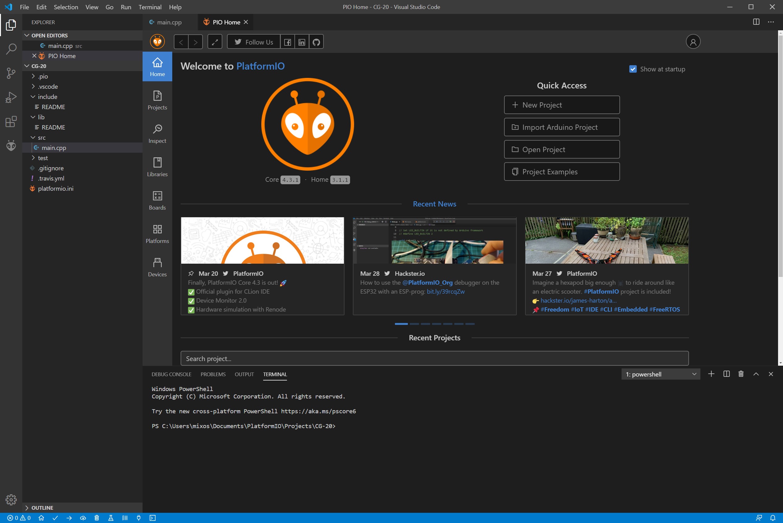
Compiling and upload of the code are done using the PlatformIO IDE as mentioned above. This is a new generation toolset for embedded C/C++ development that you need to install to use the code above. You will need first to download and install the Microsoft’s Visual Studio Code as PlatformIO IDE is built on top of it. To do so follow the short instructions here. Then re-launch the Visual Studio Code to apply the changes. You will now see the PlarformIO extension active as in the screen below:
Next click “New Project” -> Add a project name -> Select board: WeMos D1 mini Lite -> Framework: Arduino -> Finish. You will then see a list of directories and files on the left. Select the main.cpp and paste the code found above in the editor. Now it’s time to compile the code and check if everything is fine. Before you do I would advise adding: #include <Wire.h> library in the list of headers as this is needed during compiling. Also, be sure to install the necessary libraries from the library manager:
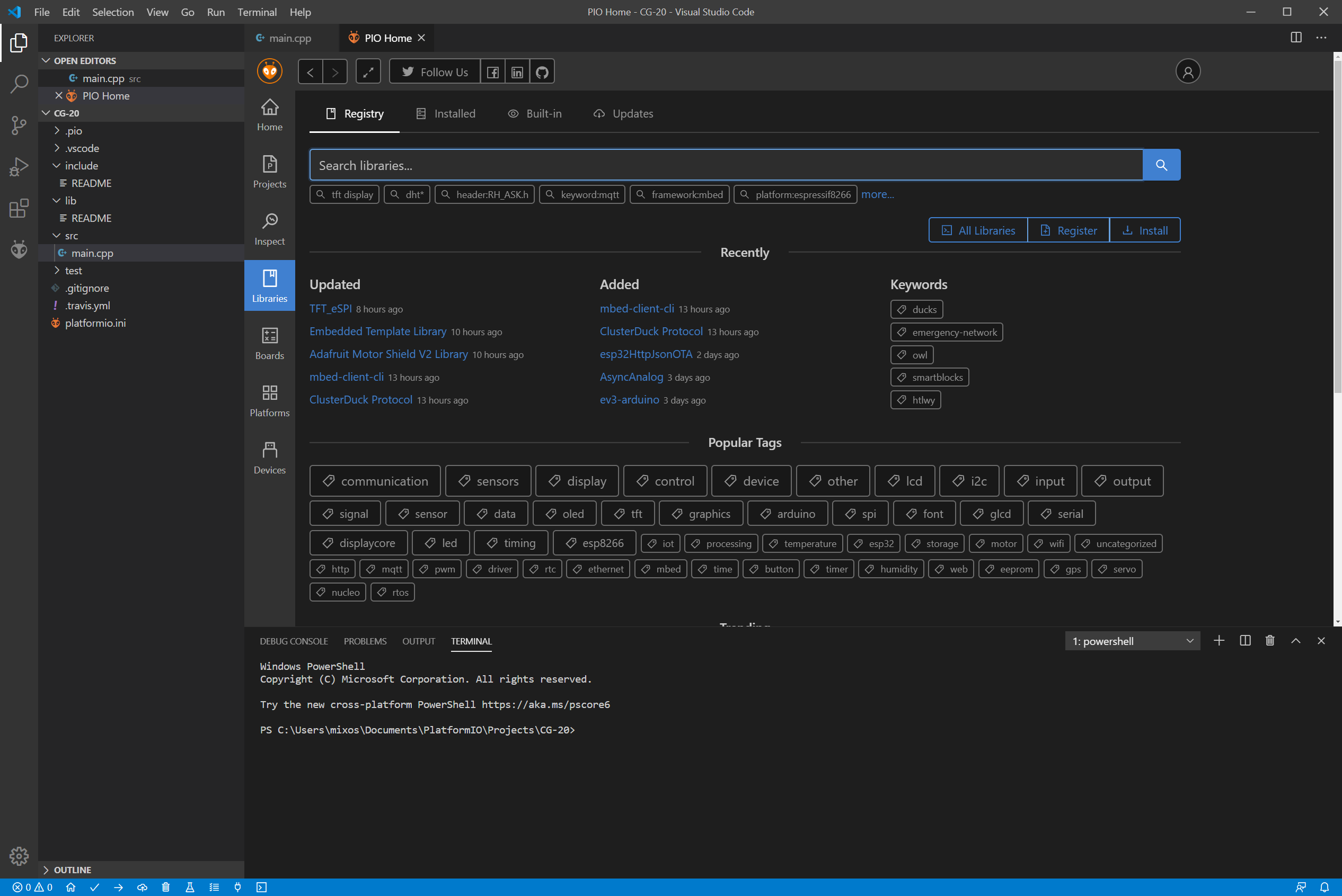
The libraries needed are:
- Adafruit GFX Library
- Adafruit ILI9341
- Adafruit TouchScreen
- WifiManager
- XPT2046_Touchscreen
In our case, we had to manually download Adafruit_TouchScreen library and place it in the following path:
C:\Users\<your username>\.platformio\lib
as the library from the build-in manager didn’t work for us. Now it’s time to compile the code using the “Build” button. If everything is fine the code should compile successfully.
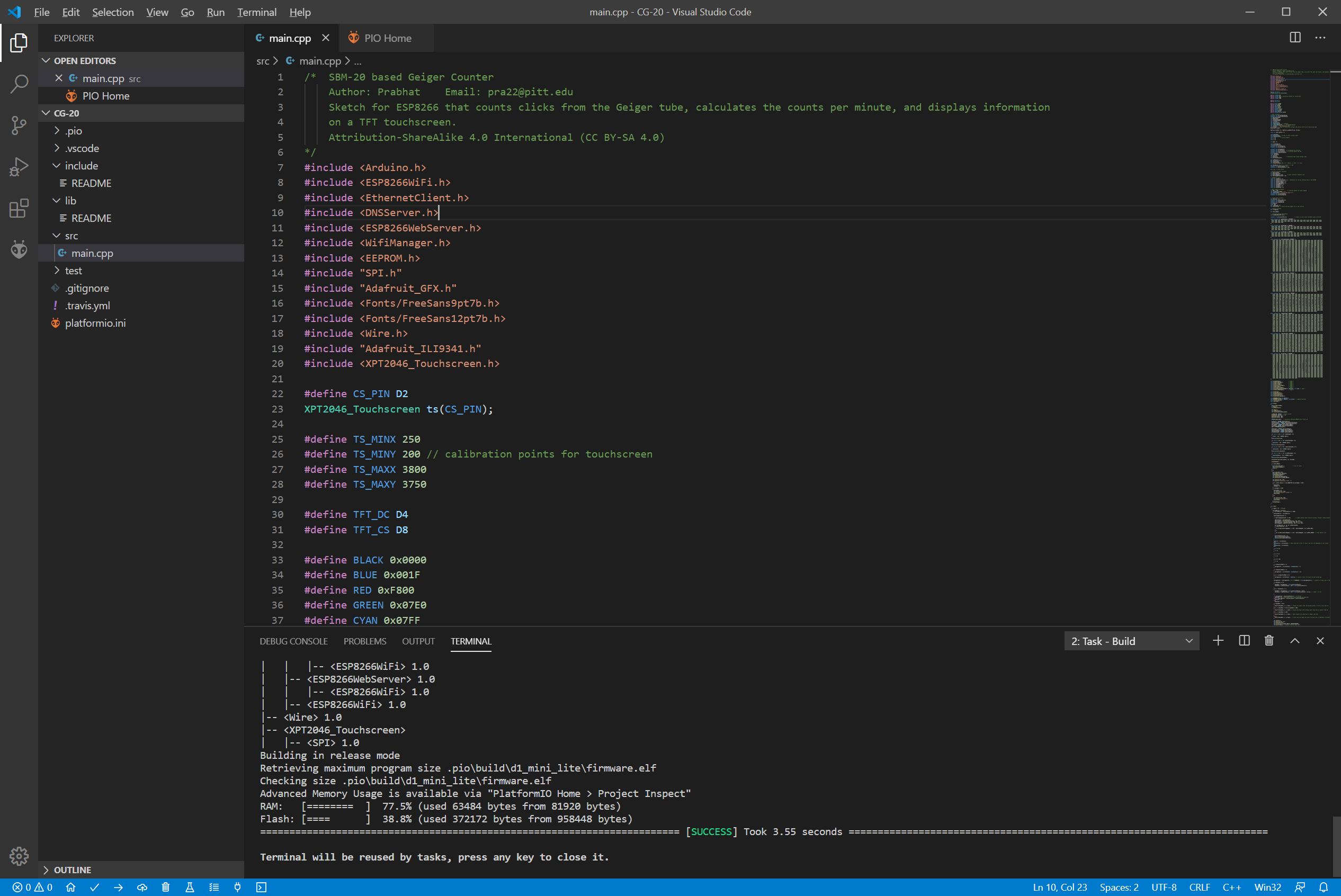
Next, we are ready to upload the code to our WeMos D1 board. To do so click the “Upload” button at the bottom of the page. Wait for a few seconds and the code will successfully be uploaded.
Demo
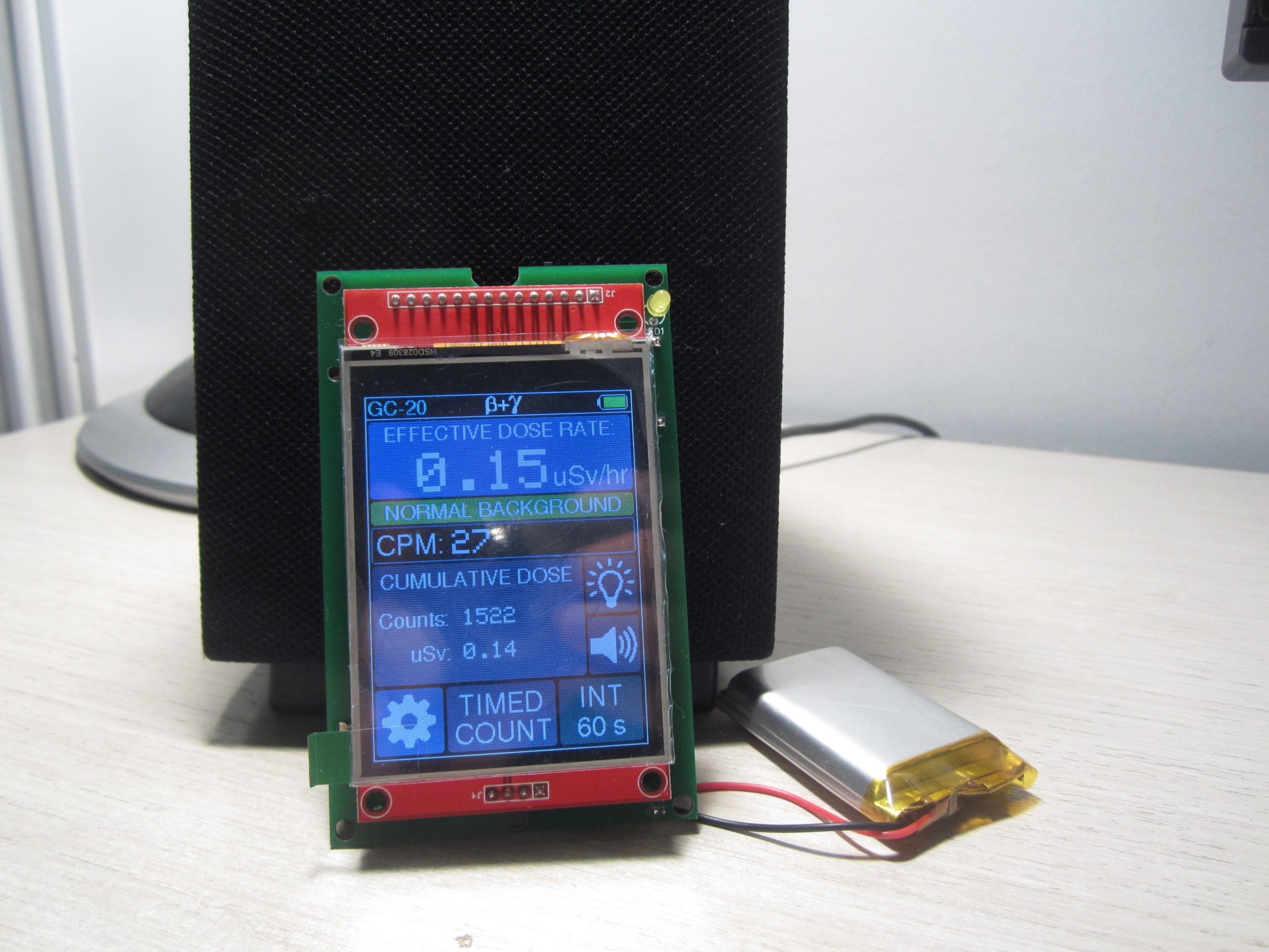
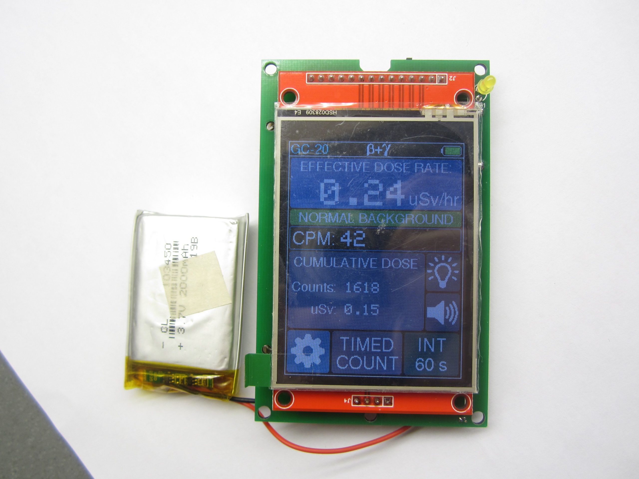
You should now see the screen come up with the home page being displayed as shown in the image below.
Testing the Geiger Counter with various radioactive sources
To test the device, some radiation sources were placed next to it and it was detected as shown in the video below:
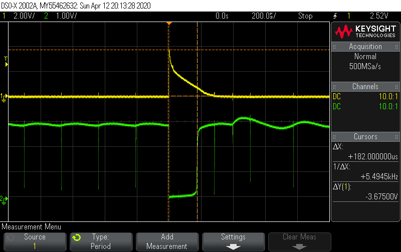
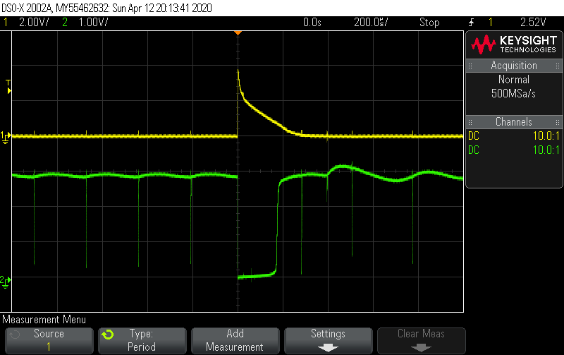
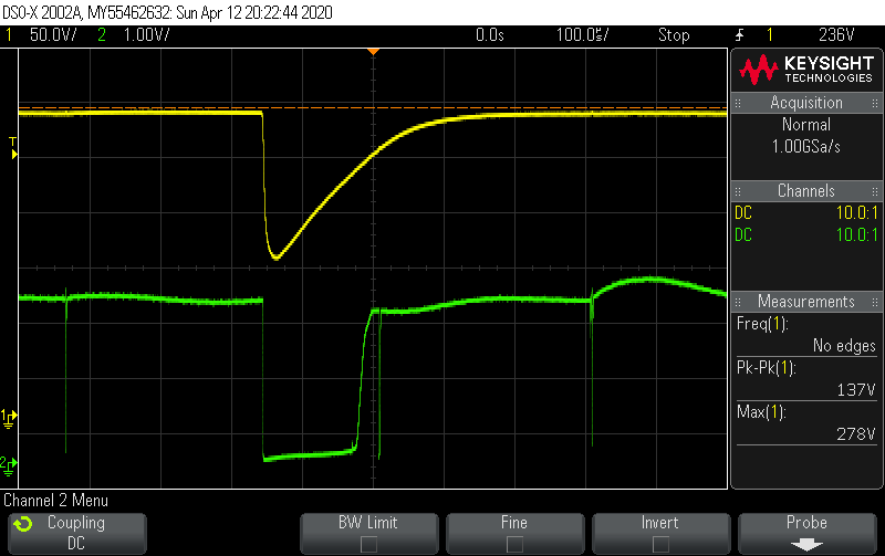
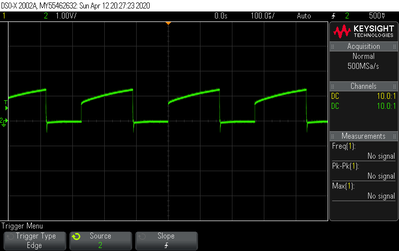
Oscilloscope Measurements
Improvements
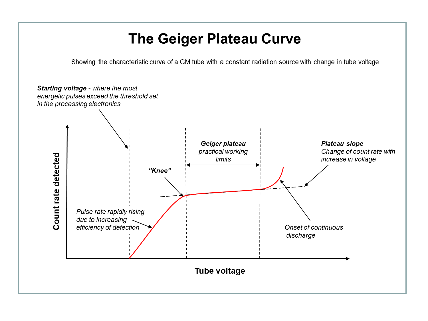
While the Geiger counter seems to work fine for detecting hard β and γ photons, we should note that the tube working voltage can go as high as 280Vdc using the above 555 timer oscillator. This voltage is below the recommended operating voltage (350 – 475V) for the SBM-20 tube and seems to operate out of the plateau region (100V length) where the tube’s response is flat. So, we would recommend improving the high voltage power supply to a source that can generate higher voltages. This will help to operate the tube on the manufacture recommended voltage.
Conclusion
The GC-20 comes with several new features that allow users to make several changes to the configuration/setup via the user interface, and to make it easy to follow, Prabhat created a user manual for the device to show how it is used. Going through the manual might also help offer better insight into how the code works.
The improvements and features inculcated into the Geiger counter by Prabhat makes it more desirable compared to the regular ones in the market and this goes to show the power of improvement which DIY can bring to a project.
All project files are attached under the download section and do feel free to reach out to me via the comment section if you had any difficulty replicating the project.
A video demo of the project by Prabhat can be found on Youtube.