
Solenoid, Relay, Valve Driver with Current Regulation
- Rajkumar Sharma
- 102 Views
- easy
- Tested
- SKU: EL141008
- Quote Now
- 0 Likes

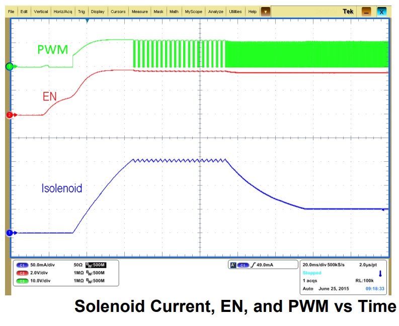
The project presented here is a PWM current driver for solenoids, Relays, and valves. The board will regulate the current with a well-controlled waveform to activate and reduce power dissipation at the same time. The solenoid current is ramped up fast to ensure the opening of the valve or relay. After the initial ramping, the solenoid current is kept at peak value to ensure the correct operation, after which it is reduced to a lower hold level in order to avoid thermal problems and reduce power dissipation.
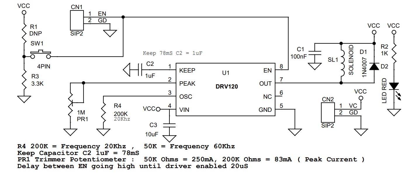
The peak current duration is set at 78ms with an external capacitor C2. The current ramp peak level can be adjusted using the PR1 trimmer potentiometer in the range 83mA to 250mA, the default PWM frequency is 20KHz, PWM frequency can be changed between 20Khz to 60Khz using the external resistor R4. The enable pin has an internal pull-up, so normally chip is enabled, pulling down the enable pin brings the chip into disable mode.
Features
- Power Supply 6V to 24V DC
- Load Current up to 250mA
- Peak Current Duration 78mS
- Peak Current Adjustable range 83mA to 250mA
- Start-Up Delay Approx 25uS
- PWM Frequency 20Khz
- On Board Switch to disable the output
- Enable Pin for External Connector
- Header Connector for Power and Solenoid
- Fast Ramp-Up of Solenoid Current to Guarantee Activation
- Integrated Sense Resistor for Regulating Solenoid Current
- Solenoid Current is Reduced in Hold Mode for Lower Power and Thermal Dissipation
- Internal Supply Voltage Regulation
- Thermal Shutdown, Threshold 160 Degree Centigrade
- Undervoltage Lockout (UVLO), Threshold 4.6V
- Compact Design
- PCB Dimensions 22.23 x 17.78mm
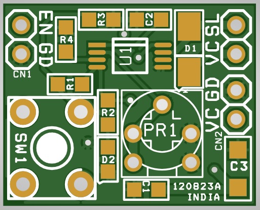
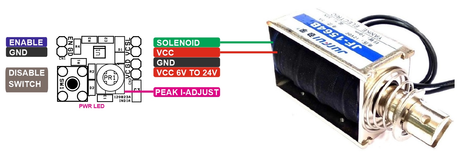
Connections and Other Details
- CN1: Pin 1 Enable (High = Enable, Low = Disable) High = 4V to 7V, Pin 2 = GND
- CN2: Pin 1 VCC 6V to 24V DC, Pin 2 = GND
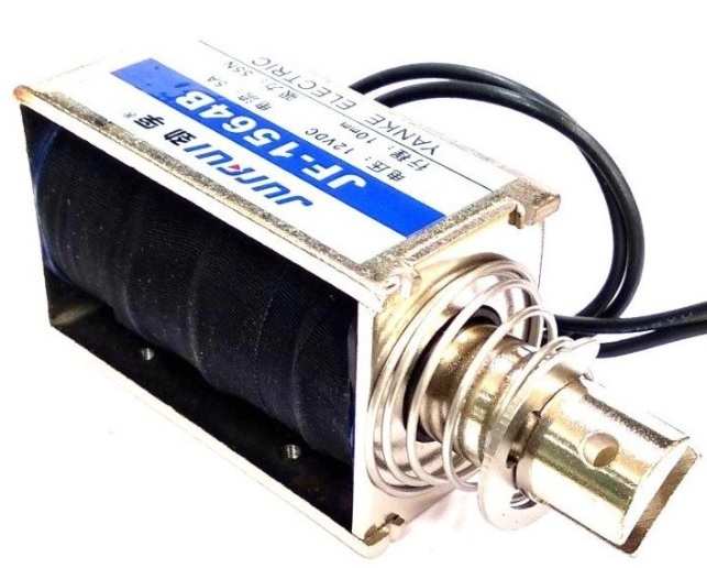
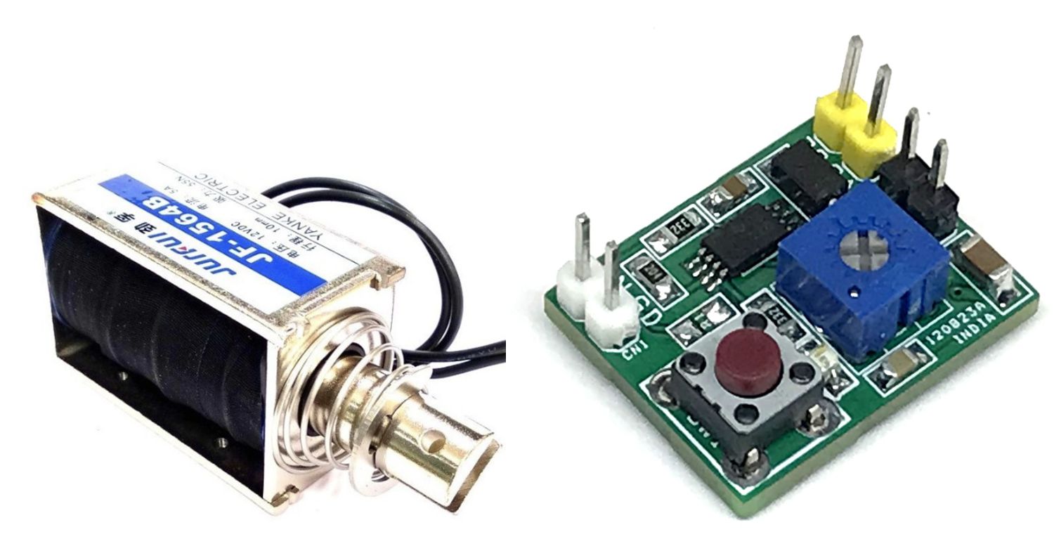
- SL1: Pin 1 = Solenoid, Pin 2 VCC (Connections for Solenoid)
- D2: Power LED
- SW1: Disable Switch Push to Disable
Schematic
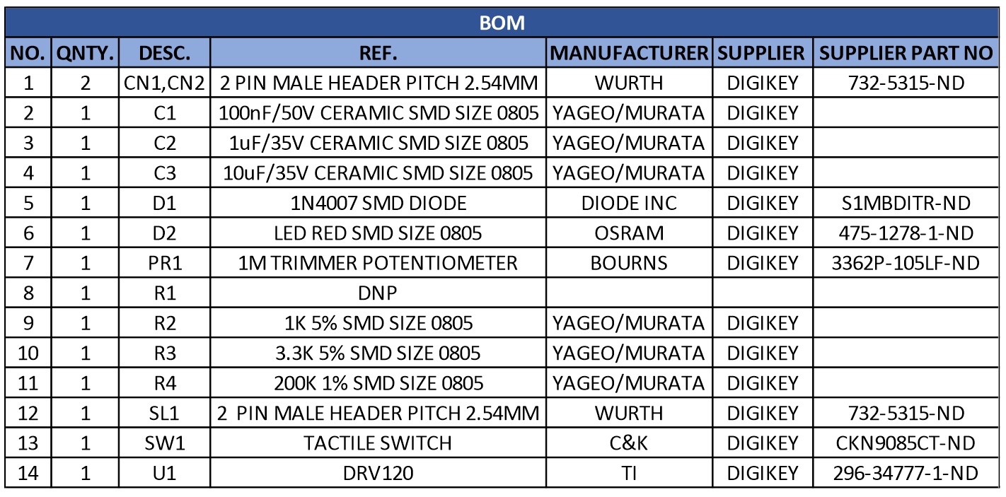
Parts List
| NO. | QNTY. | DESC. | REF. | MANUFACTURER | SUPPLIER | SUPPLIER PART NO |
|---|---|---|---|---|---|---|
| 1 | 2 | CN1,CN2 | 2 PIN MALE HEADER PITCH 2.54MM | WURTH | DIGIKEY | 732-5315-ND |
| 2 | 1 | C1 | 100nF/50V CERAMIC SMD SIZE 0805 | YAGEO/MURATA | DIGIKEY | |
| 3 | 1 | C2 | 1uF/35V CERAMIC SMD SIZE 0805 | YAGEO/MURATA | DIGIKEY | |
| 4 | 1 | C3 | 10uF/35V CERAMIC SMD SIZE 0805 | YAGEO/MURATA | DIGIKEY | |
| 5 | 1 | D1 | 1N4007 SMD DIODE | DIODE INC | DIGIKEY | S1MBDITR-ND |
| 6 | 1 | D2 | LED RED SMD SIZE 0805 | OSRAM | DIGIKEY | 475-1278-1-ND |
| 7 | 1 | PR1 | 1M TRIMMER POTENTIOMETER | BOURNS | DIGIKEY | 3362P-105LF-ND |
| 8 | 1 | R1 | DNP | |||
| 9 | 1 | R2 | 1K 5% SMD SIZE 0805 | YAGEO/MURATA | DIGIKEY | |
| 10 | 1 | R3 | 3.3K 5% SMD SIZE 0805 | YAGEO/MURATA | DIGIKEY | |
| 11 | 1 | R4 | 200K 1% SMD SIZE 0805 | YAGEO/MURATA | DIGIKEY | |
| 12 | 1 | SL1 | 2 PIN MALE HEADER PITCH 2.54MM | WURTH | DIGIKEY | 732-5315-ND |
| 13 | 1 | SW1 | TACTILE SWITCH | C&K | DIGIKEY | CKN9085CT-ND |
| 14 | 1 | U1 | DRV120 | TI | DIGIKEY | 296-34777-1-ND |
Connections
Output Measurements
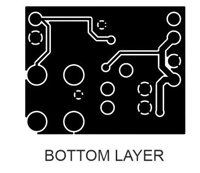
Gerber View
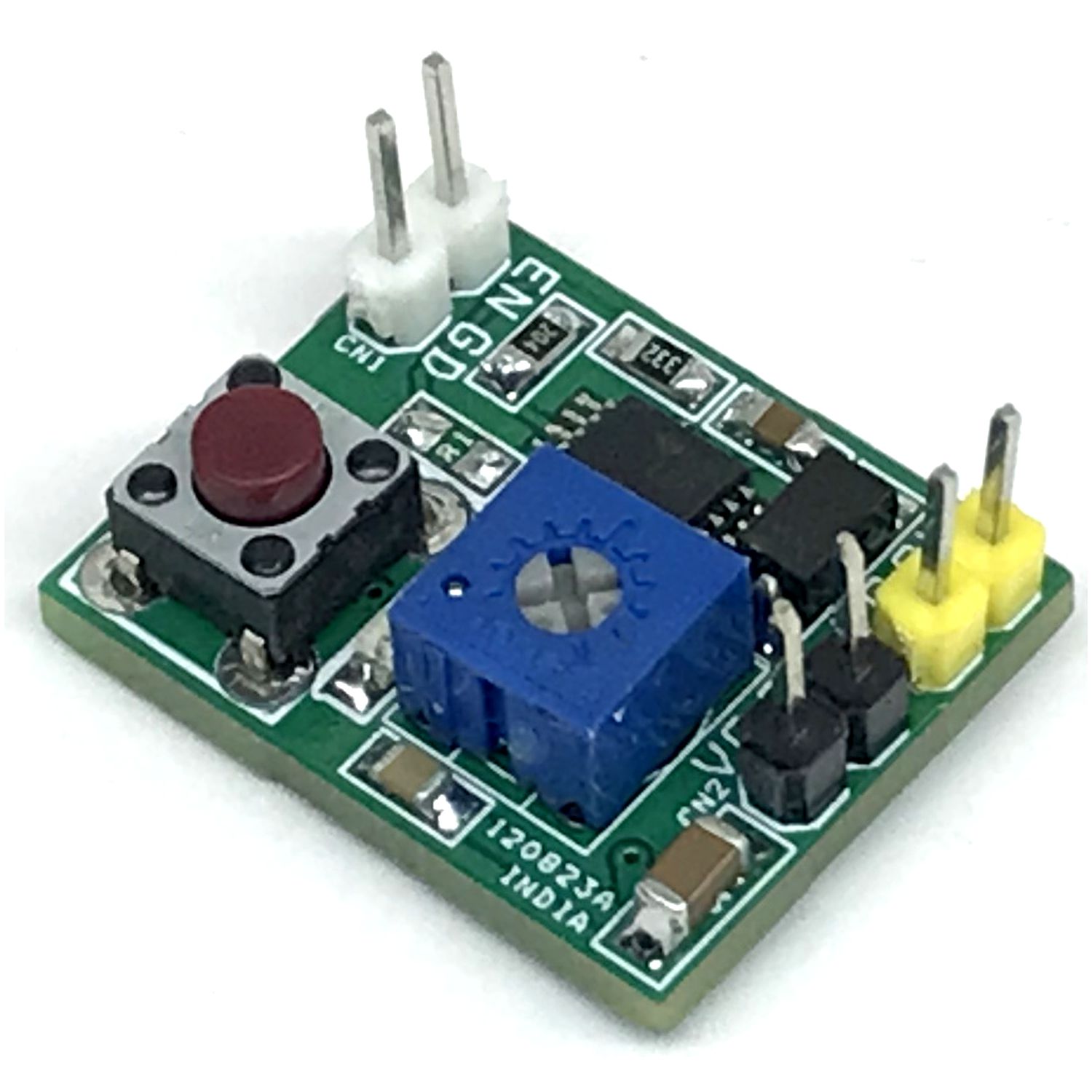
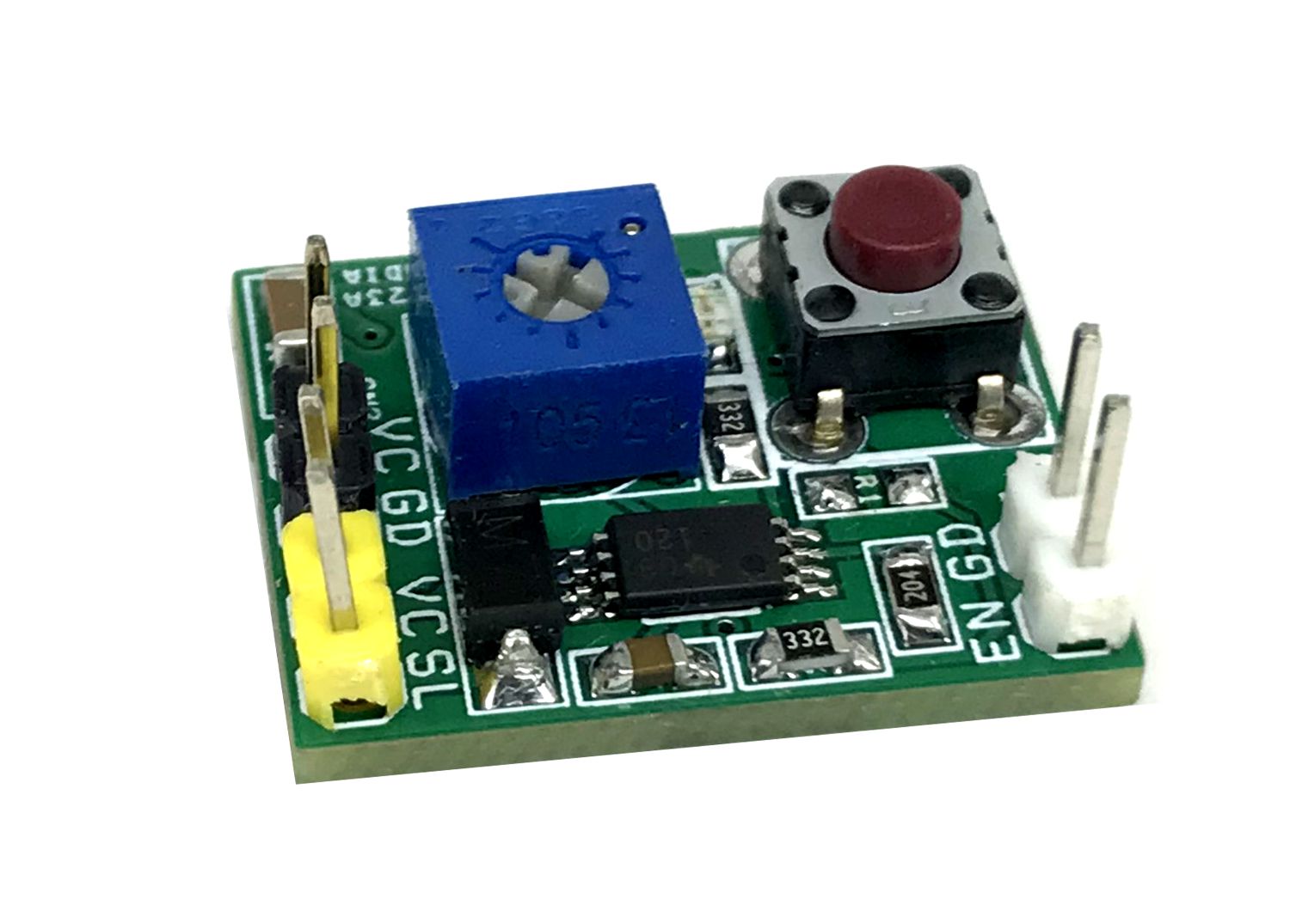
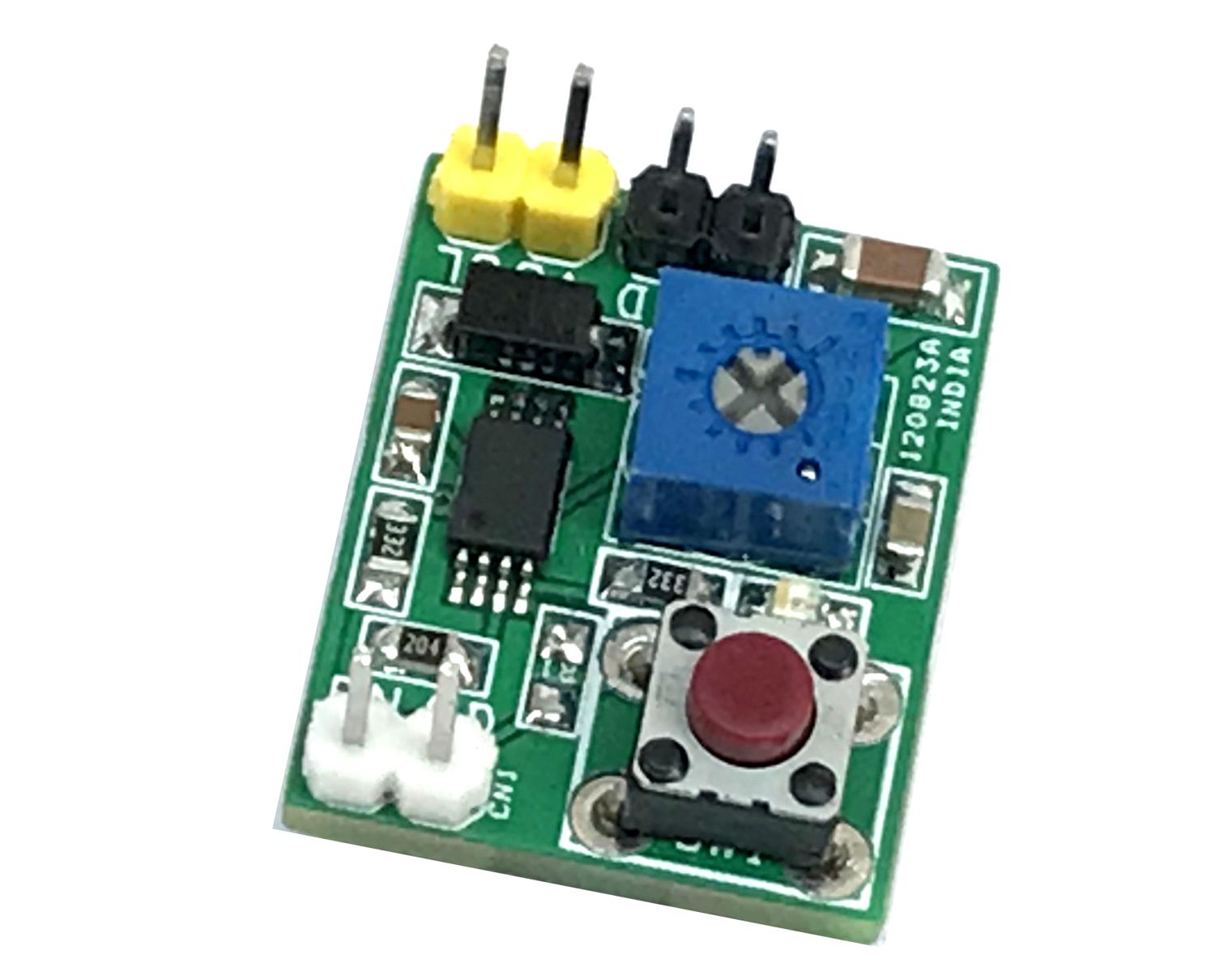
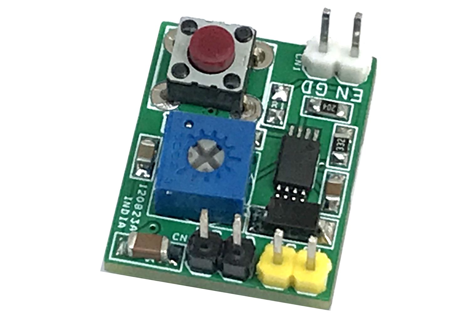
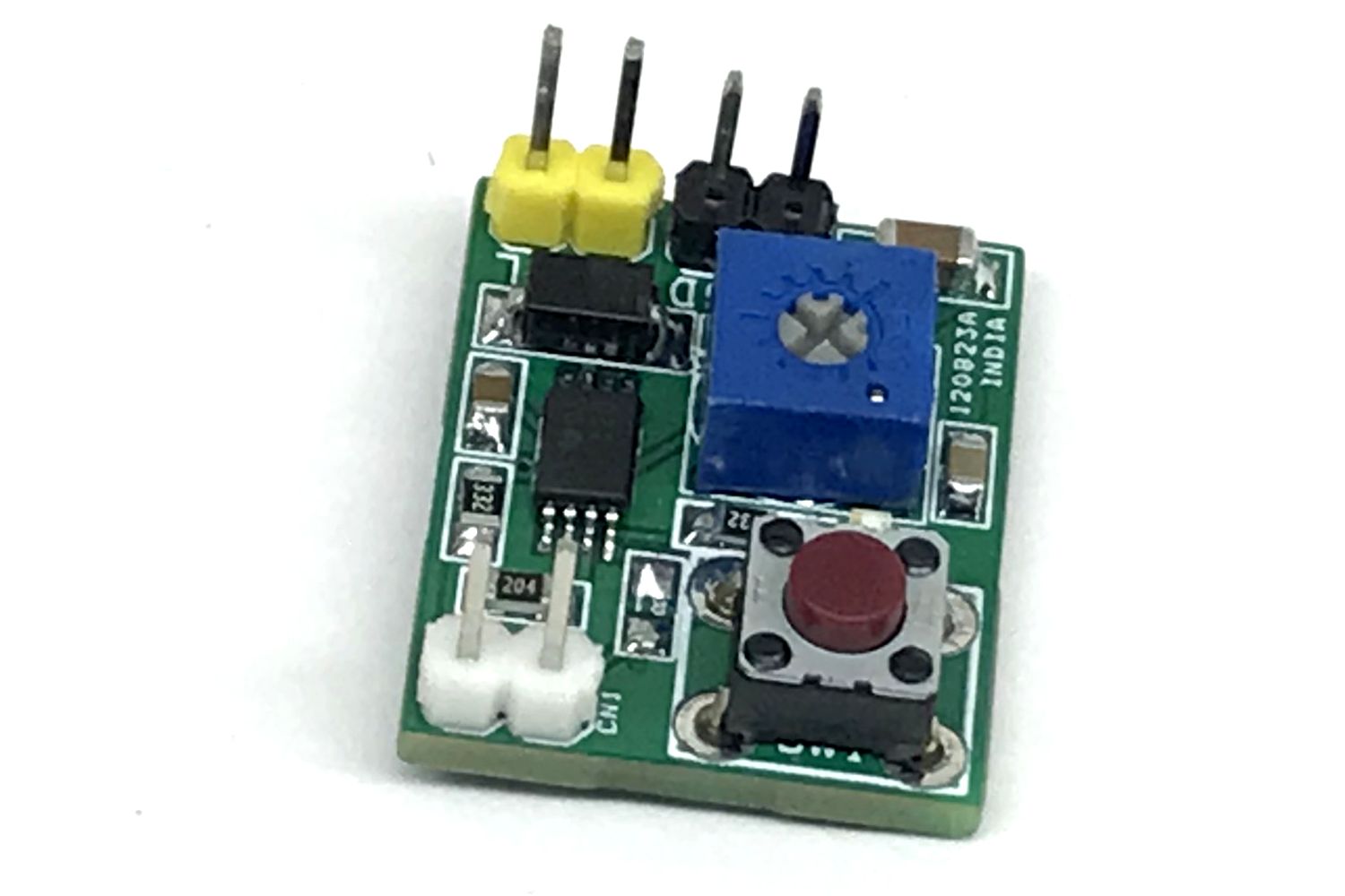
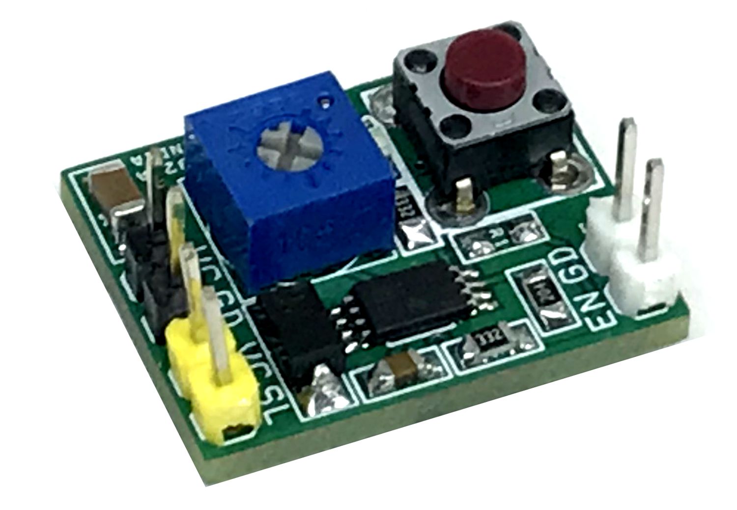
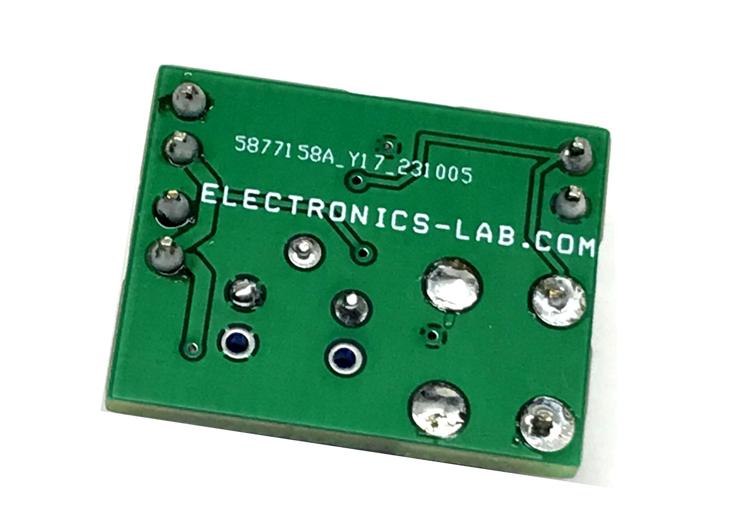
Photos
Video
DRV120 Datasheet
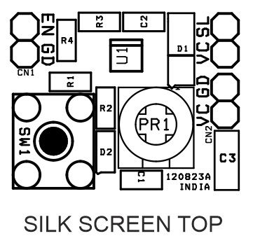
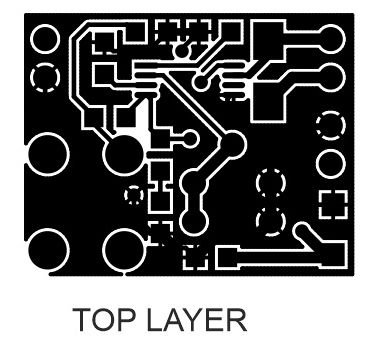
PCB