USB PIC Programmer
This page is dedicated to everybody needs to program a PIC (Microchip) device via USB port. Looking on the web for ready-to-use projects, I found a good one called Open Programmer, coming with several schematics, PCBs and Open Source code.
This page is dedicated to everybody needs to program a PIC (Microchip) device via USB port. Looking on the web for ready-to-use projects, I found a good one called Open Programmer, coming with several schematics, PCBs and Open Source code. The original link is http://openprog.altervista.org/OP_ita.html
What concerned me was the need to mount, on the mainboard, a specific socket board depending on the model of PIC being programmed. Moreover, the proposed layout did not meet my personal “compact look” ideas. So, I propose here a small layout version of that circuit, adopting a single smart on-board ZIF socket. This version sacrifices many non-PIC microcontroller models. I will thank everybody proposing a larger range implementation, suitable to program Atmel and other devices. Anyway, if your goal is to program PIC devices, you are on the good site.
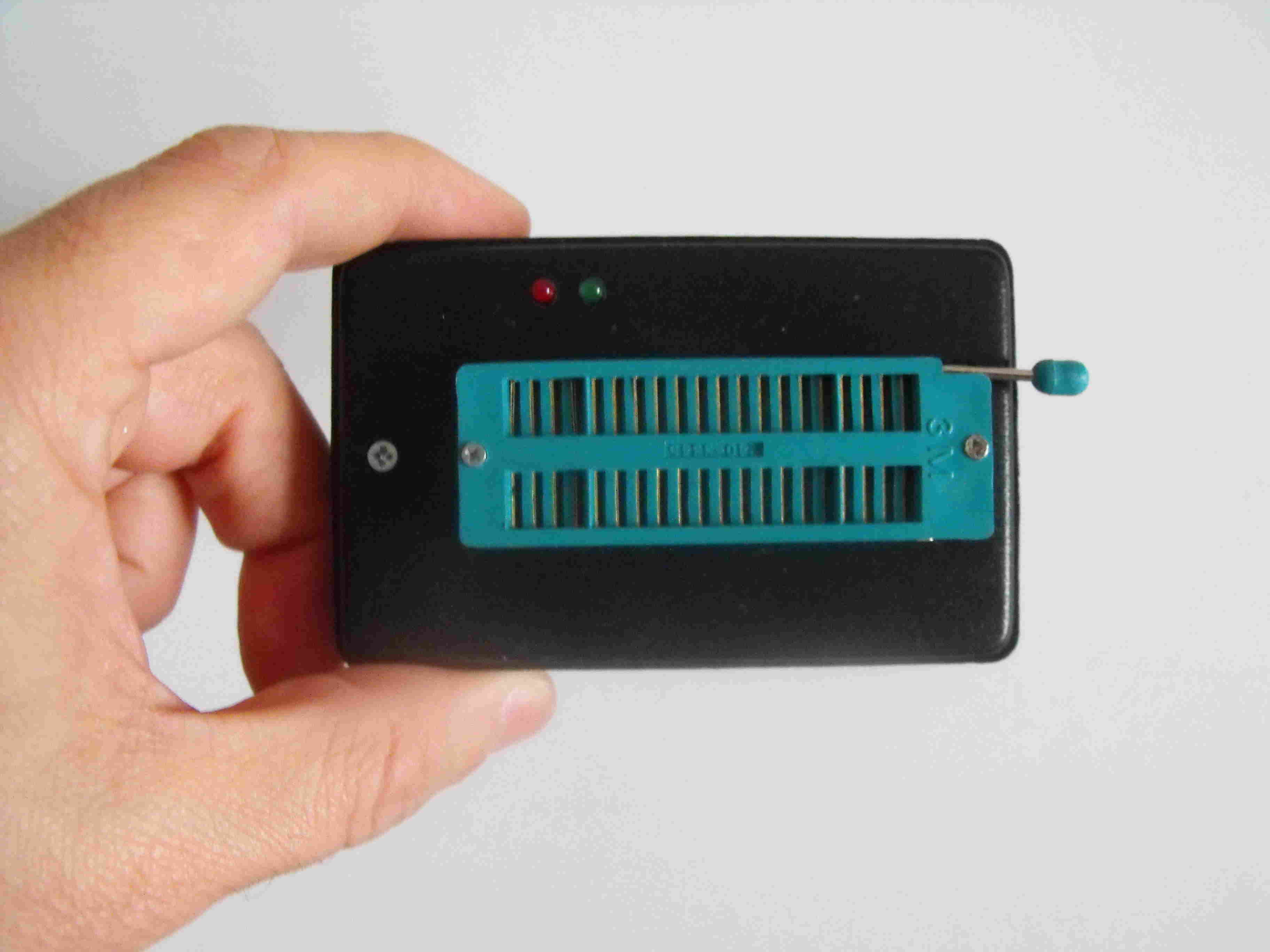
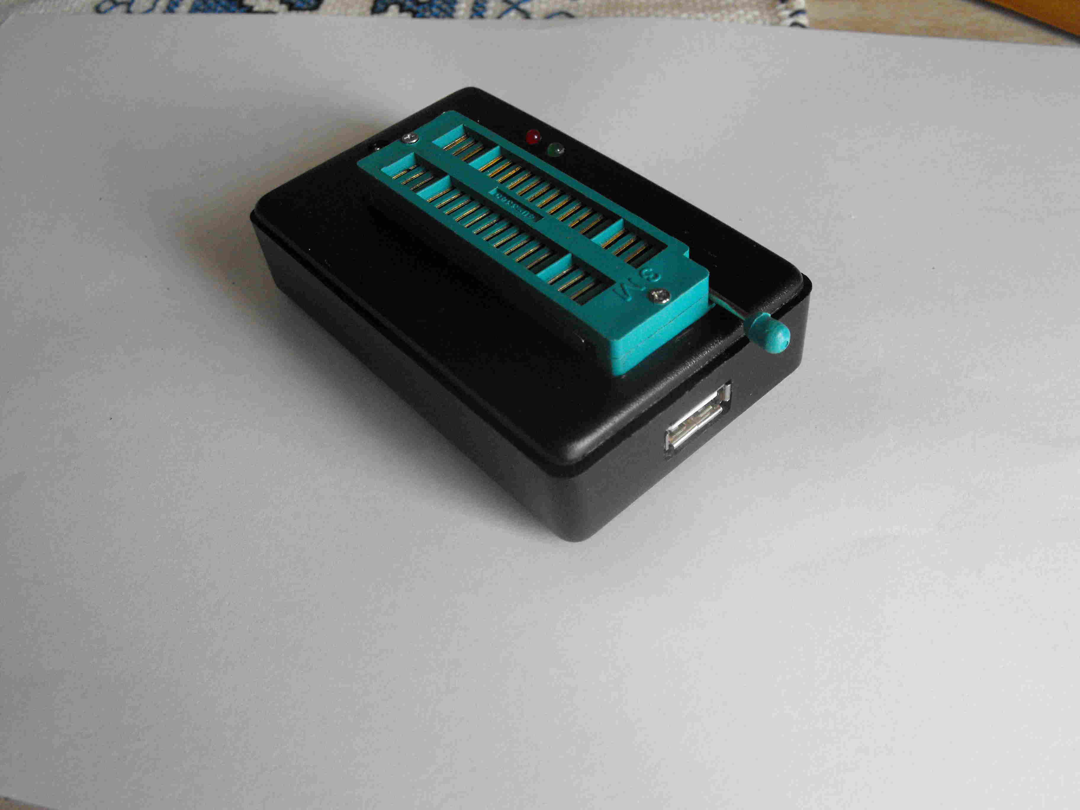
A small box, a USB connector, a ZIF socket, two leds. That’all in my compact proposal.
Description
The details are available on the original project mentionned above. Hereafter, I shown my Compact version, with a schematic, PCB layout and instruction for assemby and inserting it in a very common little plastic box. At the bottom of this page, I supply a copy of the program to load on the PIC18F2550 used to manage the programming functions, as well as a copy of the PC side program. I tested the program up to Win-8 without problems. Take into account that, on the original site, a newer version of both Firmware and Software is available.
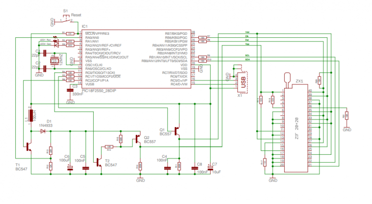
Schematic
Assembly
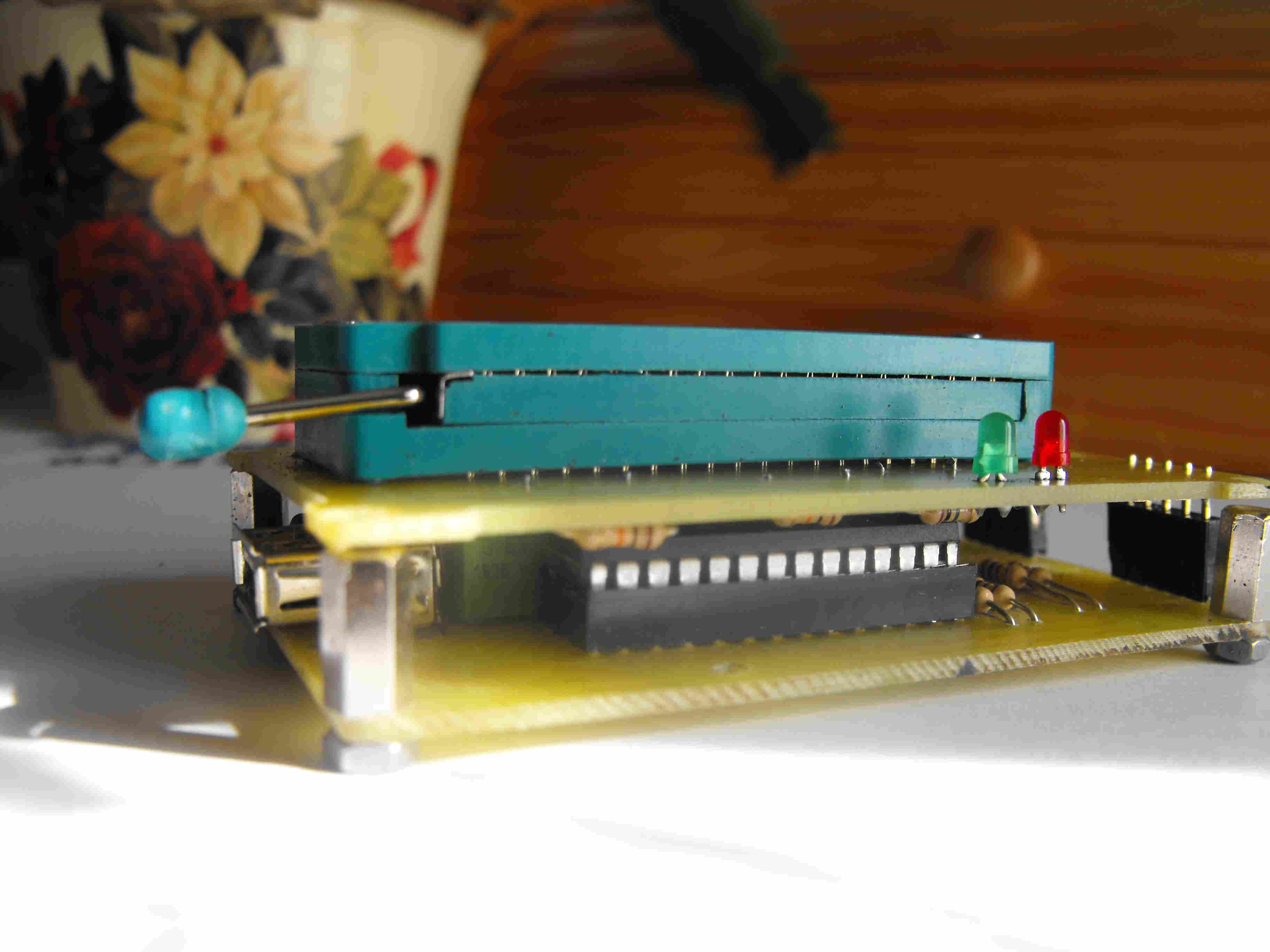
Build first the main module using low profile components being under 10 mm of height from the PCB surface, since a second board will be mounted over that one. Mount 4 ten millimeters height columns to allow the final assembly of the second board. Use low profiles parts to fix the columns, otherwise some manual metals removal can be needed to reduce the occupation on the copper side.
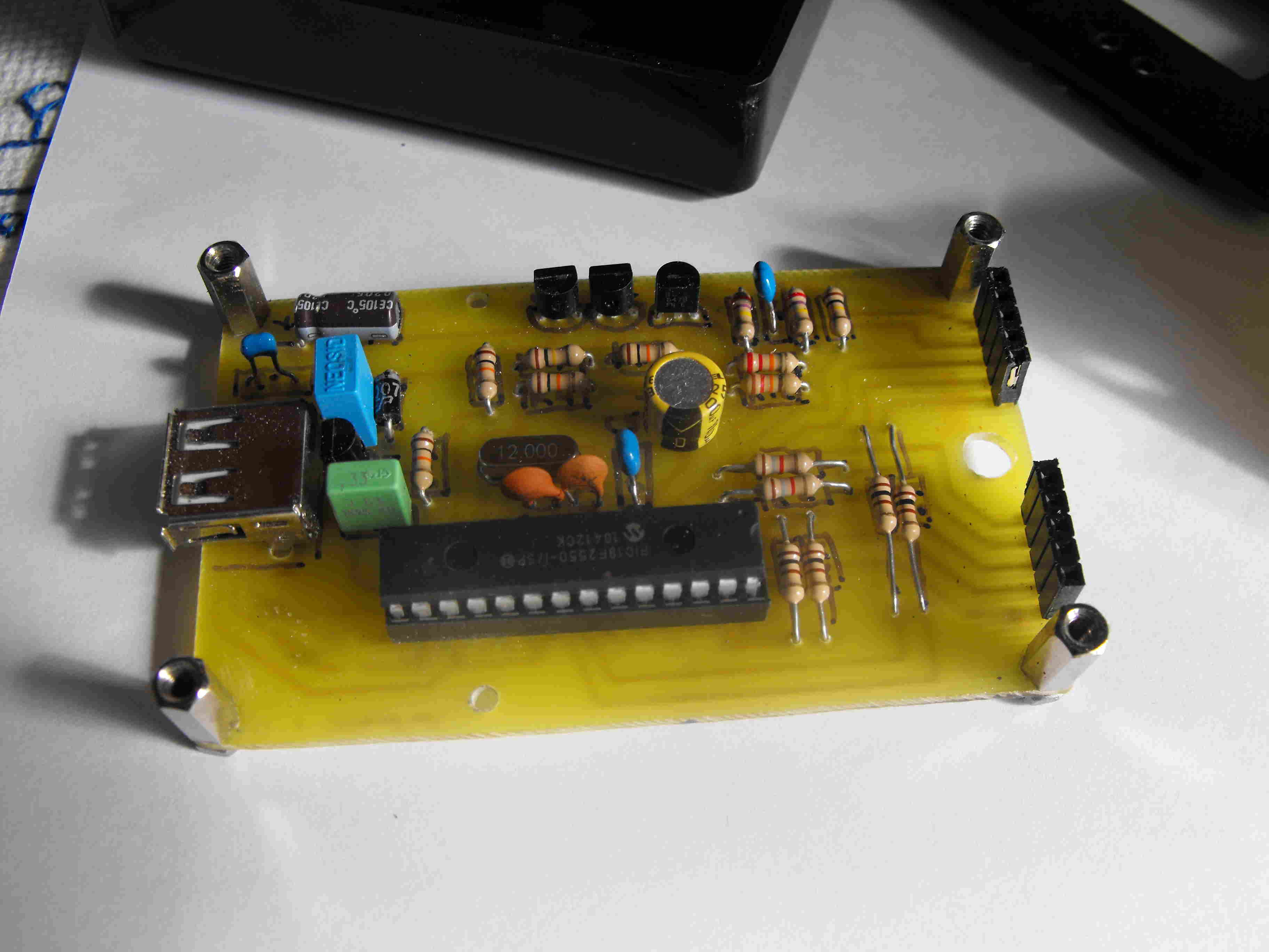
The ZIF is a quite delicate component befor final soldering. Pay attention to avoid any force that can lead to damage or deformation. It is better to do 1.2 mm holes to facilitate the insertion of the ZIF socket in the PCB. During soldering jump several pins each time, following a spiral line, adopting a sequence that allow to warm-down a pin while you are soldering the next one.
Once the two circuits are ready, connect them using the strip lines, and block assembly using the columns. Use countersunk screws of countersunk holes to avoid the screws being too hight respect to upper surface of second PCB. Just the socket and the two leds shall emerge.
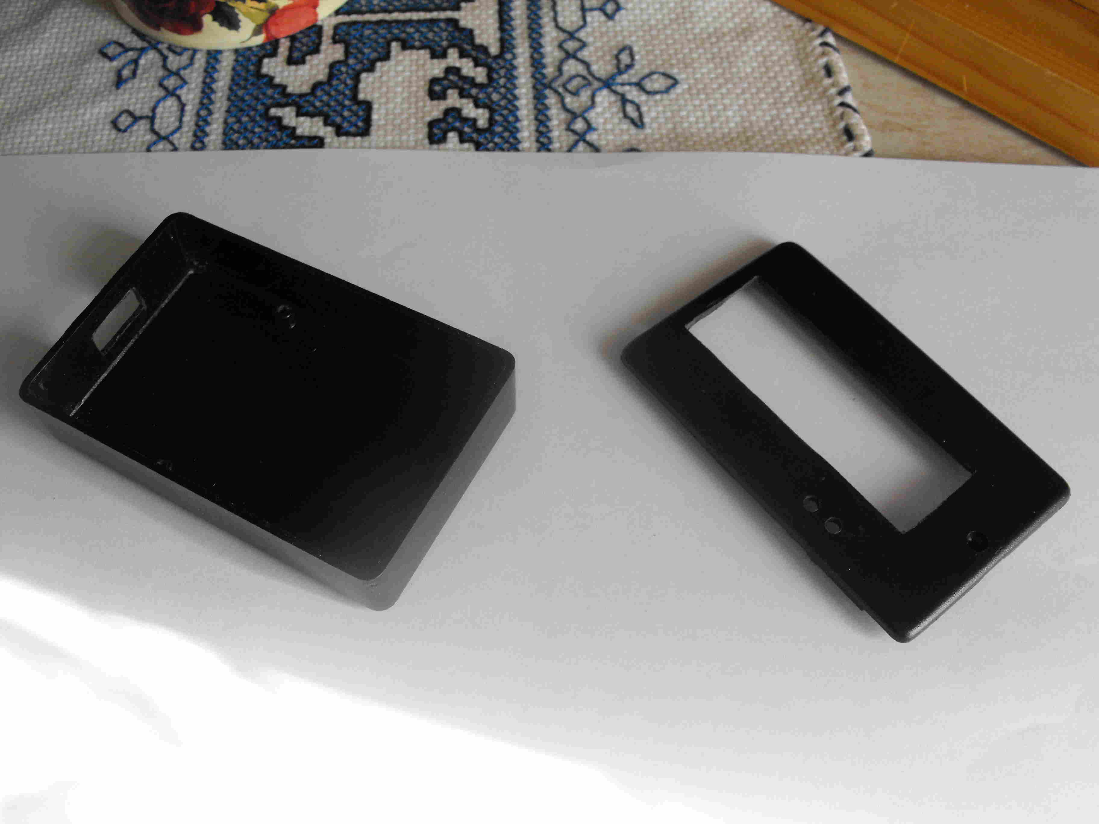
The plastic box is very common. You shall create holes to let emergent parts to exit from its surface: the socket, the two leds (or a single bi-colour led), the USB socket on a short side. It is a A-type female
The Box
After a few attempts and corrections you will reach the final result. The cover has a border that shall be modified to host the circuits, but your logic will drive you. The first PCB has to be fixed on the box using the supplied screws.
Hereafter the final result:
Software
As said before, the original site offers both the firmware and the PC side software. Anyway, to start using this programmer, I suggest you to use the versions I used at time of project editing, available hereafter for downloading. After some tests, you can try the new updated versions available on the original site. Of course, if you have not a programmer yet, a friend should program the programmer first, for you. After that first step, you will be automous!
You can download the PC software on the link below – OpenProg.rar
You can download the PIC .hex file on the link below – OProg.hex
Usage
Connect the programmer to the PC with a male-male A-Type USB cable. The device is seen as a generic one. The green led blinks speedy first, announcing the connection in progress. Than slowly, indicating that the connection phase is completed. The PC software allows bot writing and reading the EEPROM of any PIC mounted on the ZIF socked. The test functions allow to measure the Vpp high voltage generated by the step-up converter present on the main circuit. That voltage is anyway already verified by the firware itself.
The PIC to be programmed has to be positionned on the ZIF socket as shown by the following picture. An hi-res version of this picture is available HERE for being printed and attached on the back of the programmer itself.
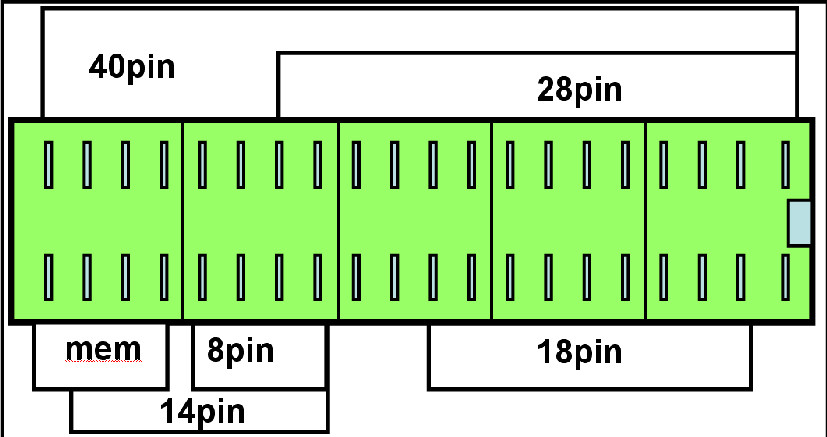

Thank you very much for your circuit so far Iam trying to make one but can not see clearly the parts placement. please kindly post clearer schematic and parts placement .
Thank you, but not see cleary the parts placement, please kindly post clearer shematic and parts placement, thanks
I’ve uploaded on the downloads section above, schematic, PCB and layout in PDF format.
what is the dimension of the pcb layout.please tell the dimension of the pcb layout.
You can print the PCB from the PDF file in the download section and it will be in correct dimensions.
another PIC programmer that needs a programmer to use program the PIC that runs every thing . What ????????????
Yeah there are a lot of people writing these articles and don’t seem to understand you need a programmer to build the programmer that they are writing about and if they already had one then why do you need this one. What a really stupid article
Thank you, but not see cleary the parts placement, please kindly post clearer shematic and parts placement, thanks
Please open the schematic from the downloads list to view it in high resolution
Can I program dsPIC30F2020 through this programmer??, I havnt see it in the open prog device list.
the sourse code dont work , eror – fuse / line 930 / : 0100000022DD
plase help / thanks
I have the same problem, have You find a solution?
the sourse code dont work , eror – fuse / line 930 / : 0100000022DD
plase help / thanks
I have the same problem, have You find a solution?
I tried the circuit, when I connected to computer it is showing “USB not recognized” error. plz help.
Please double check your circuit according to the schematic, parts orientation and placement and check if the PIC mcu is correctly flashed with the .hex code
Hi everybody! The fuse error may occur 1) when the Pic is not in the list of supported devices . 2) when its position on the Zif socket does not match the one foreseen for its pin count, referrying to the picture in the project. 3) when the usb connection is not established (green led initially quickly blinking, than more slowly). Please check all that and correct/retry. Email me on further problems. Thanks.
Another hint: use the latest sw version available at http://openprog.altervista.org/OP_eng.html
dsPic: never tested. Refer to the above site for further details and take into account that my variant support a less number of devices. No memories nor mcu needing scl/sda programming. It is really Pic oriented.
Hello ….. Is it possible to send a preprogrammed 18F2550 fee for the pic usb programmer.
My Email = on4aci@telenet.be
You may contact the author on their website above.
Hello sir, thank you so much for sharing this effort.
i have a question about the hex file. Is it a general bootloader or specific for this MCU?. I mean can i use another IDE to program other microcontrollers using this Usb PicProgramer?
Sorry for if my questions look a bit strange
Best regards
The code is written specifically for PIC 18F2550 and the programmer is limited to program PIC mcus only. You may refer to original design if you want to program ATMEL AVRs.
I can not programming Atmel avr IC’s
This programmer is only used for Microchip microcontrollers.
Hello Mr Stefano, thanks for sharing the knowledge.
is it possible to program the mcu with the (pickit 2 firmware) instead of the Oprog.hex. so that I can use mplab??
thx in advance
We are sorry, this project is based on the oprog.hex only.
really it’s work….??????
Hello, my device gets detected but when i click device test, it shows USB voltage too low (VUSB<4.5V). WHat may cause this and how can i solve it
sir.
thank you
i done the pcb.
it’s a great job.
please explain how to use the software too,
(ms.febin111@mail.com)
i’m a beginner so can you help me and write a list of components with their values
You can find the components clearly indicated on the schematic PDF file.
I looked under downloads but do not find mention of a PDF file anywhere.
It’s on this page, on the download section.
can i use proton ide to program pic u controller using this programmer ..
You can use any IDE to write and compile your code and then use this programmer to burn the .hex file into your mcu.
sir can you plz mail me the code of 18f2550 if possible
Source code isn’t available at this moment. You may email the author about it.
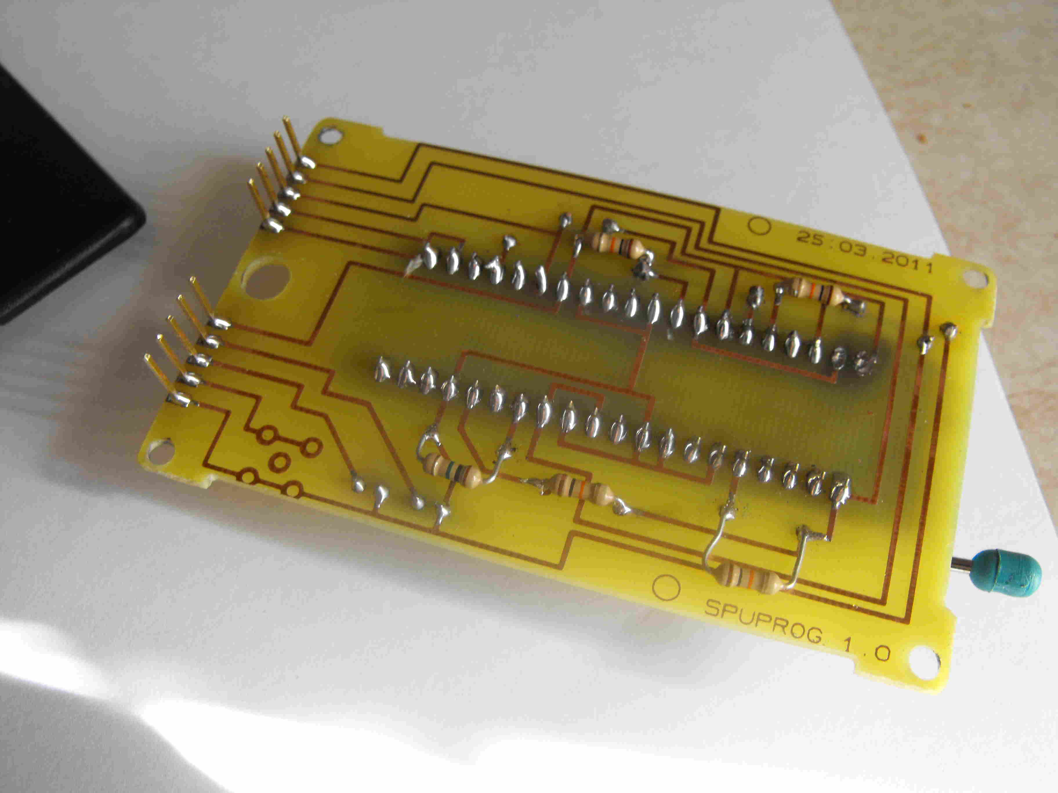
The PCBs are horizontally flipped? On the image of the soldering of the top board the routes appear to be mirrored.
Yes, PCBs are flipped. You can direct print them from PDF file and etch your own boards.
Can u give me the original source program of the pic18f2250 that use in the project? I want to know how it work. Please …..
Thank You for this project.
You may refer to the source website above to obtain the code if available.
Thanks a lot for this nice programmer article. I have implemented the circuit and designed a new PCB for it using Cadsoft Eagle. It is working perfectly. I am ready to send the pictures in addition to my PCB design to any enthusiast who is willing to build it… Cheers!.
Hi Jamal, thanks for your input. I encourage you to post your design on the community and send me the link to include it in this page.
Dear Mr Aldeen, thank you very much indeed … could you please mail me the eagle files ? Thanks again !
How do you load the oprog.hex onto the pic on the lower board? Do you need a second programmer, or is it possible directly from pc?
You will need a second PIC programmer connected to your PC.
Thanks! 😀
I DO NOT HAVE THE 18F2550 PIC uC.CAN I USE PIC 18F4550 INSTEAD WITH SOME SLIGHT MODIFICATIONS TO THE PCB PINOUT. THANKS IN ADVANCE FOR YOUR ANSWER.
The two microcontrollers rely on the same family and 18F4550 has more available IOs. So It should work on this project with a modification of the PCB. I would suggest to give it a try.
can we programe atmel ics? with this?
No, this will only work with PICs
it means that it can program PIC18f452?
and what is the reason that it can not program atmel and avr ics?
if you know how to make universal programmer? or atmel and avr programmer, so please share it with me….
thanks
Sure, it should be a supported device. You may check here for a complete list of the supported devices: http://openprog.altervista.org/OP_eng.html#Support . I can also see that some ATMEL AVRs are also supported.
PIC 18F452 in not in that list
give me authentic one so i will abe to program my device and others too..
thanks
why do we need a pic programmer for loading oprog.hex on lower board? most of the tutorials have same thing,y cant we make a pic programmer without using an existing programmer? is there any way for that?
Apparently no, I have search for year and only found one non PIC Programmer but it uses a Parallel port which of course most PCs don’t have any more. I’ll keep looking or figure it out on my own. What a waste of an article
I can’t program pic16f628A (errors during verification) But with 16f84A and 16f877A it works very well. Please help me.
pic16f628A is in the supported devices, so you shouldn’t have a issue. Please double check connections and verify mcu is not damaged.
Thanks so much sir for this information.I intend constructing this programmer will the hex file for the pic18f2550 you uploaded still work for the circuit as at today or will the hex file from microchip site do the same job for me? Please I look forward to reading your reply
Thanks