

audioguru
-
Posts
12,026 -
Joined
-
Last visited
-
Days Won
13
Content Type
Profiles
Forums
Events
Everything posted by audioguru
-
You forgot to say if the 10V output from your power supply must be AC or DC. You also forgot to say if the input is AC or DC and its voltage and frequency. Did you know that the output power from your power supply will be 10V x 1000A= 10000 Watts? Where will it come from? What will it be used for?
-

How to adapt Li-ion batteries to replace AA batteries
audioguru replied to johnpham's topic in Power Electronics
mAh is how long a battery will supply the current, not its maximum current. Besides, a load only draws as much current that it uses and not more unless it is shorted. Your car battery can provide hundreds of Amps to the starter when it is cold but the clock uses only a few thousandths of an Amp from the same battery and the clock does not blow up. A lithium battery cell is about 3V when it must be disconnected (or it is destroyed), to 4.2V when it is fully charged and no higher. Then two cells in series produce 6V to 8.4V. AA cells are 1.6V for new alkaline to 1.45V for fully charged Ni-MH. 8 in series produce 11.6V to 12.8V when new or fully charged. A special charger is needed for a Lithium battery. A low battery voltage must be detected and it turns off the battery. Use three Lithium cells in series for 9V to 12.6V or use a "boost converter" to boost the voltage of two cells. -
Your attachments do not work. Usually a circuit built on a solderless breadboard with messy wiring all over the place and intermittent contacts does not work. I have designed and built thousands of prototype circuits, some VERY complicated, soldered together on a compact stripboard layout and they all work perfectly. Your voltage jumping at a steady low frequency indicates "motor-boating" low frequency positive feedback. It might be a part that fails when it heats (overheats?) then works again for a while when it cools. Your attachements are actually links to All-About-Circuits where we must join to see them. Instead attach them here to your replies.
-
basic electronics lab experiment single stage CE amplifier
audioguru replied to pvshah's topic in Electronics chit chat
The very simple kit should have told you what Vcc is and what Vi and Vo are. -
simple question about switch,wattage,loading...
audioguru replied to Barbra's topic in Datasheet/Parts requests
You said it is rated at only 24W. Why are you overloading it with 10 times too much load? -
how to make a mailbox light? guys
audioguru replied to Barbra's topic in Electronic Projects Design/Ideas
The cheap Chinese solar garden light has a dim light for only a couple of hours following a sunny day. It lasts only a couple of months before its LED, solar panel and battery rust away. No light following a cloudy day. The cheap solar panel actually gets sunburned. Use the pcb circuit from a solar garden light and amplify its output with a transistor to drive a bright high current LED. Use a larger high current high quality solar panel and battery. Properly seal everything to prevent rust. -
Solderless breadboards cause many problems reported on all the electronic forums. The many tangled wires and rows of contacts have capacitance between them that cause many electronic circuits not to work properly. The contacts are frequently intermittent. I made thousands of prototype circuits soldered on stripboard where the strips of copper were cut to length with a drillbit plus a few jumper wires form half a pcb and the components form the other half. Every circuit worked perfectly and many looked good enough to be sold as the finished product.
-
To use your transformer then many resistor values will need to be re-calculated and changed. The 16.6VAC will have a peak voltage of only 23.5V. The improved circuit is designed to use a 28VAC/4.3A or 30VAC/4A transformer. If you re-design the circuit then with your transformer its maximum regulated output will be about 16.5VDC at about 1.5A.
-
I talked in ordinary electronics terms. Since you do not understand electronics then I cannot explain it better. Why do you need a radio transmitter that might cause illegal interference with radio stations and important communications?
-
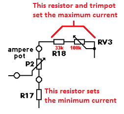
Look at the schematic above on October 30, 2016 where it shows the RV3 trimpot that sets the current limit calibration accurately.
-
Here in Canada (and in the USA) FM radio station frequencies are at odd frequencies like 99.9MHz, 100.1MHz, 100.3MHz so 100.0MHz is not used. Even frequencies like 100.0MHz, 100.2MHz and 100.4MHz might be used in Europe. If you use a quartz crystal oscillator and a harmonic of it at 100.0MHz then the accuracy depends on the spec's for the crystal.
-
It is inefficient to boost the voltage too high then drop it down. Why does the amplifier need a supply of 140V to produce only 100V? Won't the extra 40V cause lots of power waste as heat?
-
February 23 above on this page has the latest schematic of the revised 3A lab power supply.
-
I do not know which circuit the ebay pcb uses, maybe it is wrong. The original circuit and the ones modified on this website use a 0.47 ohm current sensing resistor R7. Then when the current setting pot is turned to maximum the current is limited to about 3.0A. The Chinese modification for the Banggood kit might do it differently.
-
I buy electronic parts from Digikey and Newark because they have offices and warehouses in my country and they stock everything. What can't you find?
-
How to find best Obsolete components
audioguru replied to Hook's topic in Sell/Buy electronics - Job offer/requests
If you find any obsolete components that still work then kiss them goodbye and bury them. Then use modern components instead. -
Hi Army Vet. Did you build the original circuit or the modified circuit? Which power transformer and opamps did you use? The dim power LED indicates that the transformer voltage is too low maybe because it is overloaded with something shorted or because the rectifier diodes are connected wrong. Maybe the main filter capacitor is connected backwards? When the current regulator light is turned on what is the load, the voltage setting and current setting? When the output voltage is 1V what is the load, the voltage setting and current setting?
-
An audio amplifier with a supply voltage as high as 200V will produce about 500W into an 8 ohm speaker and produce almost 12A peak, not a few milli-amps. Oh, is your amplifier going to use an old output transformer that has not been used for 50 years? Then its output power might be 1.8W into 8 ohms.
-
It sounds awful like a squeaker, not like a speaker because the speaker is too small and it is not mounted in an enclosure. The LM386 amplifier produces only 0.11W (almost nothing) into 8 ohms when its supply is only 5V.
-
Look in Wikipedia for Voltage Multiplier. It has an AC input to capacitors and diodes.
-
A dissertation is an essay. Why do you want an essay? Don't you understand what the parts in the circuit do? Do you know how transistors and opamps work?
-
More useful to do what function?? Many of us do not use those Japanese transistors. Instead we use BCxxx European transistors or 2Nxxxx American trasnsistors,
-
An IC is an "Integrated Circuit" that is a tiny chip with many transistors, resistors, diodes and capacitors on it. Look in Google for a longer explanation.
-
Issue with a 10 Watt Power LED Driver Supply
audioguru replied to Yoda Man's topic in Electronic Projects Design/Ideas
An LED is driven from a current, not a voltage. We do not know if the high power SMD LED has a built-in current-limiting resistor. The LED sets its own voltage so the 17V - 19V will probably drop to 12V when the 12V/900mA LED is connected. 10W is a lot of heat for an LED. Do you have a suitable heatsink for it? -
Issue with a 10 Watt Power LED Driver Supply
audioguru replied to Yoda Man's topic in Electronic Projects Design/Ideas
A blue LED is about 3.2V but some high power LEDs have a few of the LED chips in series. If your blue LEDs survive the high current of 900mA then the eight you connected in series need about 25.6V which is much higher than the rated output voltage of the driver. Why eight LEDs? Try using a load of 10.5V/900mA= 11.67 ohms or a 12 ohms/20W resistor.
