Search the Community
Showing results for tags 'arduino'.
-
 A water level indicator detects and indicates the level of water in an overhead tank and relays the information back to a control panel to indicate whether the tank has a high or low water level. In this tutorial, I am going to use the ULN2003 IC to create a simple, inexpensive water level indicator. Using this circuit you can easily control the wastage of water and electricity. Watch this video, for detailed step by step instructions on how to build this circuit and to know how this circuit works. Towards the end of the video I will also discuss whether its really worth building this circuit. Components Required For this tutorial we need: 1 x ULN2003 IC 8 x Different Color LEDs 8 x 1K Resistors 1 x 220Ohm Resistor 1 x Buzzer A Long Ribbon Cable, and A Breadboard or a Custom Built PCB About The ULN2003 IC The notch on the top indicates the starting and stopping points of the numberings of the chip. Starting from left to right going counterclockwise this is the Pin number 1 of the IC. On the left hand side Pin 1 to 7 are the Base Inputs. On the right hand side Pin 10 to 16 are the Collector Outputs. Pin 9 is the Common Cathode node for flyback diodes (required for inductive loads). And, Pin 8 is the Common Emitter shared by all channels of the IC. This pin is typically tied to ground. The UNL2003 IC contains 7 High Voltage, High Current NPN Darlington Transistor Arrays each rated at 50V, 500mA in a 16-pin DIP package. You can connect the IC directly to a digital logic (like Arduino or Raspberry Pi, TTL or 5V CMOS device) without an external dropping resistor. The ULN2003 is known for its high current and high voltage capacity. The Darlington pairs can be "paralleled" for higher current Output. To know more about this IC, please check out my "Tutorial No. 51: All About ULN2003 IC", the link is in the description below. Circuit Diagram The circuit is very simple. I have connected 7 LEDs to the 7 OUT Pins of the IC via 1K Resistors. On my left, are the 7 digital inputs which are connected to a ribbon cable. The other end of the ribbon is submerged in the water tank with exposed terminals at various heights to detect the water levels. Along with the 7 wires, there is an eighth wire that stays at the bottom of the tank and is connected to the +ve terminal. As the tank starts filling up, the water level rises and a conductive path is created between the positive terminal and the base of Darlington Transistor inside the IC. Hence a logic HIGH is sent to the Input Pin of the IC which leads to the corresponding OUT Pin to go LOW lighting up the LEDs one by one starting from the bottom Red to the top Green. The bottom Red LED indicates lack of water and the top Green LED indicates that the tank is 100% full. You can also add a buzzer to the circuit to get an audio indication when the tank is full. If you want to be super funky, you can also add a relay module which can turn on and off the water pump. Breadboard Demo Before assembling the components on a PCB, lets do a quick test on a breadboard to make sure our logic works as expected. For this demo, I am going to fill up a coffee mug with normal tap water. As you can see, the LED indicators go up from bottom Red to the top Green as I keep filling the mug. The buzzer starts buzzing when the mug is 100% full. Hence, our setup is working as expected. The Board So, this is how my board looks like in 2D and 3D. If you want to learn how to design a PCB, please check out my "Tutorial No. 45: Transformers PCB BADGE", the link is in the description below. Component Assembly Now, lets solder the components to the board. Lets first solder all the resistances to the board. Then, lets solder all the LEDs to the board. I am using a 3mm Green LED as the power indicator. Next, I am soldering the IC base to the board. Since I care a lot about my ICs and micro-controllers, I never solder them directly to the board. In case of an ICs, I always try to use an IC bases or if a base is not available I use female pin headers. After soldering the IC base, I am soldering the Buzzer to the board. Now to conclude the setup, I am soldering the Ribbon Cable to the board. For my setup, I am only using half a meter long cable. But in a real-world scenario, you will definitely need a cable longer than this. Final Demo So, this is how the final setup looks like. As the water level rises, a conductive path is created between the positive terminal and the base of Darlington Transistors inside the IC. This triggers a logic HIGH at the Input Pins of the IC and the corresponding OUT Pins goes LOW lighting up the LEDs one by one starting from the bottom Red to the top Green. When the mug is 100% full the top green LED lights up and we also hear a noises of the buzzer. Usability To be very frank, I see more disadvantages than advantages of using this IC in building a liquid level indicator. You may have a different opinion, but my opinion is based on the below facts: The choice of the probes that will remain submerged in the liquid has to be done very carefully as they: Rust, foul and deteriorate due to "corrosion" and "electrolysis" causing the LEDs to slowly fade and finally turn off. Hence the probes need to be cleaned and replaced every 2 - 3 years. This circuit will work well with tap water, however do not use this with salt water or with any flammable liquid. If in your house you get hard-water, there will be salt deposits on the probes and you will have to clean the salt deposits on a regular basis. This circuit will not work if you have a metal tank. Replacing the contact points with something "non-corrosive" may help but I will not put my bet on that. Another option is to have "large electrodes" which will have a low impedance even when covered with impurities. To conclude I would like to say that the ULN2003 is not the best device to use for this application. You might be better using a "CMOS buffer" or inverter which needs less water conductivity to operate and also gives a more sudden output change as the input voltage rises and falls, along with "non-corrosive large electrodes". Thanks Thanks again for checking my post. I hope it helps you. If you want to support me subscribe to my YouTube Channel: https://www.youtube.com/user/tarantula3 Video: View Full Blog Post: View References GitHub: View Gerber: View DataSheet: Download All About ULN2003 IC: View Transformers PCB BADGE: View DIY Relay Module: View Support My Work BTC: 1Hrr83W2zu2hmDcmYqZMhgPQ71oLj5b7v5 LTC: LPh69qxUqaHKYuFPJVJsNQjpBHWK7hZ9TZ DOGE: DEU2Wz3TK95119HMNZv2kpU7PkWbGNs9K3 ETH: 0xD64fb51C74E0206cB6702aB922C765c68B97dCD4 BAT: 0x9D9E77cA360b53cD89cc01dC37A5314C0113FFc3 LBC: bZ8ANEJFsd2MNFfpoxBhtFNPboh7PmD7M2 COS: bnb136ns6lfw4zs5hg4n85vdthaad7hq5m4gtkgf23 Memo: 572187879 BNB: 0xD64fb51C74E0206cB6702aB922C765c68B97dCD4 MATIC: 0xD64fb51C74E0206cB6702aB922C765c68B97dCD4 Thanks, ca gain in my next tutorial.
 -
The UNL2003 IC contains 7 High Voltage, High Current NPN Darlington Transistor Arrays each rated at 50V, 500mA in a 16-pin DIP package. You can connect the IC directly to a digital logic (like Arduino or Raspberry Pi, TTL or 5V CMOS device) without an external dropping resistor. This IC features "common-cathode flyback diodes" for switching inductive loads. The ULN2003 is known for its high current and high voltage capacity. The Darlington pairs can be "paralleled" for higher current Output. The inputs are capable with TTL and 5v CMOS logic. Now, let's deep-dive and check out the internals of the IC and how it can be used in our projects. Pin Configuration and Functions The notch on the top indicates the starting and stopping points of the numberings of the chip. Starting from left to right going counterclockwise this is the Pin number 1 of the IC. * On the left hand side Pin 1 to 7 are the Base Inputs. * On the right hand side Pin 10 to 16 are the Collector Outputs. * Pin 9 is the Common Cathode node for flyback diodes (required for inductive loads). * And, Pin 8 is the Common Emitter shared by all channels of the IC. This pin is typically tied to ground. Detailed Description Inside the IC is the arrays of the 7 NPN "Darlington Transistors". Darlington Transistors were first invented in 1953 by Sidney Darlington. A Darlington pair is a circuit consisting of two Bipolar Transistors with the Emitter of one transistor connected to the Base of the other transistor. In this setup, the current amplified by the first transistor is further amplified by the second transistor. The collectors of both transistors are connected together. This configuration has a much higher current gain than each transistor taken separately. A small base current can make the pair switch to a much higher current. It appears as if it is just a single transistor, with only one base, one collector, and one emitter. Creating a high current gain approximately to the product of the gains of the two transistors: β Darlington = (β 1 * β 2) + β 1 + β 2 Since, β1 and β2 are high enough, we can write the above statement as: β Darlington ≈ β 1 * β 2 This connection creates the effect of a single transistor with a very high-current gain. The 7 outputs are all "Open Collector". By Open Collector, we mean a collector that is not attached to anything. It's just open. In order for an open collector output device to work, the open collector has to receive sufficient power. In order for an NPN transistor to work, the collector and the base both need to receive sufficient power. The base turns the transistor on, and then a much greater current flows from collector to emitter, but only if the collector has sufficient positive voltage. So if you want to connect a load to the Output of the chip with an open-collector-output, you must attach the load to a positive voltage source that is sufficient enough to drive the load. Hence, the +ve side of the load connects to the +ve voltage rail and the -ve side connects to the OUTPUT pin of the IC. Hence, when the Base current goes HIGH, the current flows from the collector to emitter and the Output logic goes LOW turning ON the LED (load) connected to the OUT pin of the IC and vice-versa. The maximum Output Current of a single OUTPUT pin is 500mA and the total emitter-terminal current is 2.5A as per the datasheet. Now, let's have a closer look at a single Darlington pair (internal circuit diagram) of the ULN2003 IC. The GPIO input voltage is converted to base current through a series base 2.7kΩ resistor connected between the Input and Base of the Darlington NPN junction. This allows the IC to connect directly to a digital logic (like Arduino, Raspberry Pi, TTL or 5V CMOS device) without the need of external dropping resistors operating at supply voltages of 5V or 3.3V. The 7.2kΩ and the 3kΩ resistors connected between the Base and the Emitter of each respective NPN transistor acts as pulldown resistors preventing floating states and suppressing the amount of leakage that may occur from the input. To maximize the effectiveness, these units contain "Suppression Diodes" for inductive loads. The diode connected between the OUT pin and the COM pin (PIN 9) is used to suppress the "kick-back voltage" from an inductive load which is generated when the NPN drivers are turned off and the stored energy of the coils causes a reverse flow of current. A reverse biased suppressing diode is also placed between the Base-Emitter and the Collector-Emitter pair to avoid the Parasitic nature of the NPN transistors. Pin 8 is connected to the GND. Device Functional Modes Inductive Load In case of an inductive load, when the COM pin is tied to a coil, the IC is able to drive inductive loads and suppress the kick-back voltage through the internal free-wheeling diodes. Resistive Load When driving a resistive load, a pullup resistor is needed in order for the IC to sink current and maintain a logic HIGH level. In this case the COM pin can be left floating (not connected). This device can operate over a wide temperature range between –40°C to 105°C. Applications Now, lets hook this IC to a circuit. As we know, the ULN2003 IC can easily drive a high-current or high-voltage (or both) device, which a Microcontroller or a Logic Device cannot tolerate. Hence, they are widely used in driving inductive loads like motors, solenoids and relays. 1. In my first example, I am going to light up a few LEDs using this IC I have connected 7 LEDs to the 7 OUT Pins of the IC via 220Ohm resistors. On my left, are the 7 digital inputs directly interfaced to either a Microcontroller or a TTL Digital Logic. When a logic HIGH is sent to the input pin the corresponding OUT pin goes LOW lighting up the LED. 2. In my second example, I am driving a Unipolar Stepper Motor using this IC In this setup, I am using Pin 1~4 for INPUT and Pin 13~16 for OUTPUT. Each OUT pin is rated at 500mA. Pin 9 has the spike suppressor diode, and is connected to the +ve terminal. By sending combinations of 0's and 1's to the 4 input pins we can rotate our stepper motor. I have used this setup in my award winning Video Tutorial: "NodeMCU Based - 3D Printed Indoor Gauge Thermometer" the link is in the description below. 3. In my third example, I am going to light-up a few AC Lightbulbs using this IC For high voltage applications, we can use RELAYS to control motors, heaters, lamps or AC circuits which themselves can draw a lot more electrical voltage/current and therefore power. We can hook up a maximum of 7 Relays to this IC. In my setup, I have connected 4 Relays to the 4 OUT pins of the IC. An AC Lightbulb is connected to the NO-pin of the relay. When we send a Digital HIGH to the INPUT pin the corresponding OUT pin goes LOW and current flows through the coil pulling the armature, completing the circuit and hence lighting up the 220V Light Bulb. Same as the previous setup, Pin 9 with the suppressor diode is tied back to the +ve terminal. 4. In my 4th example, I am going to show you guys how to obtain more than 500mA at the OUTPUT As we know that each of the OUT Pins are rated at 500mA, then how can I drive a 1Amp device? All we have to do is, tie 3 of the OUTPUT pins on the OUT side, and tie 3 of the corresponding INPUT Pins on the INPUT side. Now the 3 INPUT pins act like a single INPUT Pin. So basically, we can parallel the inputs to get a higher amplified value of paralleled output. You may ask, why did I combine 3 INPUTS and OUTPUTS and not just 2? As per the datasheet each pin is rated at 500mA but the total output is 2.5A (*** Page 4 of datasheet ****). Hence, 2.5A / 7 Pins = 0.36 Approx. So, 0.36 * 3 = 1.07Amp Approx. which is what we want. Areas of Application The ULN2003A produced by Texas Instruments can be used for: 1. Driving motors and solenoids 2. Can be used as a Relay Driver for high voltage application (7 relays at the max) 3. To drive high current loads using Digital Circuits 4. To drive high current LED's 5. To create a water level indicator circuit 6. As a LED and Gas Discharge Display Drivers 7. Can also be used as a logic buffer in digital circuits and more... For more information about the packaging and the material used, please have a look at the datasheet. The link is in the description below. Always consult a manufacturer's datasheet before assuming industrial conventions, no matter how intuitive or obvious they may be. "In the face of ambiguity, refuse the temptation to guess." - Zen of Python Thanks Thanks again for checking my post. I hope it helps you. If you want to support me subscribe to my YouTube Channel: https://www.youtube.com/user/tarantula3 Video: Watch Full Blog Post: Visit References DataSheet: Download Darlington transistor: View Open Collector Output: View Transistor–Transistor Logic: View Parasitic Structure: View Related Videos NodeMCU Based - 3D Printed Indoor Gauge Thermometer: View Acronyms TTL: Transistor–Transistor Logic CMOS: Complementary Metal–Oxide–Semiconductor Support My Work BTC: 1Hrr83W2zu2hmDcmYqZMhgPQ71oLj5b7v5 LTC: LPh69qxUqaHKYuFPJVJsNQjpBHWK7hZ9TZ DOGE: DEU2Wz3TK95119HMNZv2kpU7PkWbGNs9K3 ETH: 0xD64fb51C74E0206cB6702aB922C765c68B97dCD4 BAT: 0x9D9E77cA360b53cD89cc01dC37A5314C0113FFc3 LBC: bZ8ANEJFsd2MNFfpoxBhtFNPboh7PmD7M2 COS: bnb136ns6lfw4zs5hg4n85vdthaad7hq5m4gtkgf23 Memo: 572187879 BNB: 0xD64fb51C74E0206cB6702aB922C765c68B97dCD4 MATIC: 0xD64fb51C74E0206cB6702aB922C765c68B97dCD4 Thanks, ca again in my next tutorial.
-
Had some time this weekend and a desire to create something new and interesting, so went ahead and created an Arduino/NodeMCU based indoor dial thermometer. This device displays the temperature in degree centigrade on a D-Shaped Gauge as well as on a 7-Segment display. In addition to that, it also saves the temperature and humidity readings in a MySQL DataBase hosted on a home based Raspberry Pi Server. The data is then displayed using the "Our Smart Home" app. Awards This project got featured on Cults3D and Instructables https://cults3d.com/en/3d-model/gadget/arduino-based-indoor-dial-thermometer https://www.instructables.com/NodeMCU-Based-3D-Printed-Indoor-Gauge-Thermometer/ Components Required For this project we need: 2 x TM1637 Display Modules 1 x DHT22 or DHT11 Module 1 x NodeMCU Microcontroller 1 x 28BYJ-48 Stepper Motor with ULN2003 Driver Board 1 x 10K Resistor A 3D Printer Copper Wire and Some Nuts & Bolts Circuit Diagram The circuit is very simple. Connect the ULN2003 driver board’s IN1, IN2, IN3 and IN4 to the NodeMCUs digital pins D0, D1, D2 and D3. Then connect the OUT Pin of the DHT22 to the D5 Pin of NodeMCU. After that connect the 2 x Display Modules to the microcontroller. We are going to use a Common Clock Pin D4 for both modules. Then connect the DIO of one of the modules to D6 (TEMP) and the other one to D7 (HUM) pins on the NodeMCU. Important: Please avoid using the boot config pins D3, D4, D8 and the RTC pin D0 for the displays. Now, on the D8 Pin we are going to connect the switch. This switch has a very important role in this circuit. This switch acts as the 'home' or the 'starting point' of the stepper motor. When the switch is open Pin D8 is connected to GND through the pull-down resistor and we read a LOW. When the switch is closed, Pin D8 connects to 3.3v pin of NodeMCU and we read a HIGH. When the 'temperature changes' or the 'device boots up', the pointer starts moving 'counterclockwise'. As soon as the pointer hits the home position, Pin D8 reads HIGH and the logic moves the pointer 'clockwise' to display the temperature on the gauge as read by the DHT22 module. The Code The code starts by including all the necessary libraries. Then it defines all the variables needed for setting up the WiFi connection. Next, it assigns a static IP address to the ESP8266 (if you want to use DHCP then go ahead and delete these three lines from the code). After that, it sets up the 2 x URLs that are needed for updating the heartbeat, temperature and humidity. String URLUpdateStatus = "http://192.168.0.7/Arduino/Weather/UpdateStatus.php"; String URLUpdateTemp = "http://192.168.0.7/Arduino/Weather/UpdateTemperature.php"; Before going ahead let's have a quick look at the 2 php files. The "UpdateStutus.php" file uses an UPDATE query to update the timestamp of the device sending the request to the current epoch time and hence updating the heartbeat. <?PHP try { $Token = $_GET["Token"]; $Location = $_GET["Location"]; include "ConnectionStringArduino.php"; // Create connection $sql = 'Update `Status` SET `DateTime`=\''.time().'\',`State`=\'1\' WHERE `Device`=\''.$Location.'\' AND `Token` = \''.$Token.'\';'; $result = $con->query( $sql ); if($result === FALSE) { die(mysqli_error());} mysqli_close($con); } catch (Exception $e) {} ?> The "UpdateTemperature.php" uses an INSERT query to add a new row to the database with the current values of Temperature and Humidity. <?PHP try { $Location = $_GET["Location"]; $TEMP = $_GET["TEMP"]; $HUM = $_GET["HUM"]; include "ConnectionStringArduino.php"; // Create connection $sql = "INSERT INTO `Weather` (`DateTime`,`Temperature`,`Humidity`,`Location`) VALUES ('".time()."','".$TEMP."','".$HUM."','".$Location."');"; $result = $con->query( $sql ); if($result === FALSE) { die(mysqli_error());} mysqli_close($con); } catch (Exception $e) {} ?> This is what is written to the database and can be displayed using Google Charts, in my case, I am using the "Our Smart Home" app to display the data using php and JavaScript. Currently I am only displaying the data from the Study room and the Peg Box. To know more about my award winning "Peg Box" project please have a look at my electronics tutorial no. 34 "Peg Box with Temperature and Humidity Monitor using NodeMCU" (https://youtu.be/elH331NXPsU). After that, I am defining all the variables required for reading and storing the value of temperature and humidity. Next, I am defining all the variables and setting up any additional symbols required for displaying temperature and humidity on the TM1637 Display Module. After that, I am defining the D8 pin of the NodeMCU as the reset switch pin. We will talk about this in detail in the following sections. Next, I am setting up the Steps Per Revolution of the stepper motor as 2038 and then initializing the stepper library through pins D0 to D3. const int stepsPerRevolution = 2038; // Change this to fit the number of steps per revolution of your motor Stepper myStepper(stepsPerRevolution, D0, D2, D1, D3);// Initialize the stepper library on pins D0 through D3 One thing to note: since I need both clockwise and counterclockwise movements, I have to initialize the pins in the order shown on screen. Then in the setup() section, first I am setting up the WiFi connection and then sending a heartbeat to the server. Then I am setting up the brightness of the 7-Segments to their max values followed by starting the dht module and finally setting the pin-mode of the switch to INPUT. void setup() { Serial.begin(115200); // Initialize the serial port /*********** Setup a WiFi connection ***********/ if (WiFi.config(local_IP, gateway, subnet)) { Serial.println("Static IP Configured"); } else { Serial.println("Static IP Configuration Failed"); }; WiFi.mode(WIFI_STA); WiFi.begin(WIFI_SSID, WIFI_PWD); while (WiFi.status() != WL_CONNECTED) { delay(500); Serial.print("."); }; Serial.println("\nWiFi connected"); Serial.print("IP address: "); Serial.println(WiFi.localIP()); SendIamAlive(); // Send the initial wakeup message to the server /**********************************************/ display_TMP.setBrightness(7); // Set the display brightness (0-7) display_HUM.setBrightness(7); // Set the display brightness (0-7) dht.begin(); // Setup the DHT sensor pinMode(SWITCH, INPUT); // Declare the switch pin as input }; Now, in the loop() section I am reading the temperature using the Read_Temp() function and then sending the Temperature and Humidity values every 30 minutes and heartbeat every minute to the home server. void loop() { /** Read the temp and humidity info from ther sensor and display it on the 7-segmnet and Gauge **/ Read_Temp(); /** Sending Humidity and temperature every 30 minutes **/ if((millis() - lastTime) > timerDelay){ Serial.println("Sending Temp and Humidity");SendTemperatureAndHumidity(); lastTime = millis(); }; /** Sending I am alive message every minute **/ if((millis() - StatusCounter) > 60000){ Serial.println("Sending Heartbeat"); SendIamAlive(); StatusCounter = millis(); }; }; Next, you see the definition of the SendIamAlive() and SendTemperatureAndHumidity() functions which utilizes the WiFiConnect() function to send the values using the previously discussed URLs. The Read_Temp() function reads the temperature and humidity and updates the 7-Segment displays and moves the pointer only if there is a change in the values. The Move_Needle() function first sends the pointer to the home position using the Return_Home() function and then looks through and moves the pointer to the correct position until the stepCout is = STEPS. The value of STEPS is calculated based on the "stepsPerRevolution" which we previously set it up as 2038. So, 2038 / 2 (for half circle) = 1019 Now by dividing 1019 by 180 degrees we get the steps required to display each degree centigrade. Now to display each degree centigrade we need 180/60 = 3 divisions. Since our gauge starts from -10 and not 0 we also have to add the first 10 blocks which is (5.661 * 10 * 3) to our calculation. int STEPS = (5.661 * 3 * TEMP) + 169.833; // 5.661 (step resolution) * 3 (steps to display each °C) * TEMP + 169.833 (5.661 * 10 * 3) = since it starts from -10 and not 0) That's it as easy as that. 3D Designing Lets have a quick look at the 3D model of the project. At the front, we have The Pointer, D-Shaped Dial, and the Temperature Scale on the dial. Down at the bottom we have the Enclosure that will house the microcontroller and all other electronics components in it. The enclosure has a Lid to keep the electronic components safe and sound. At the back, we have a pocket to hold the DHT22 Module, 3 x holes for the stepper motor, 2 x groves for the TM1637 Display Module and 2 x L-Shaped Brackets to hold the top Dial to the bottom Enclosure. 3D Printing Once the 3D models were sorted, it was time for me to fire up my 3D printing oven and start printing these 3D models. I used: - 1.75mm Cold White PLA Filament, and printed the models with - 0.2mm - with 0% infill - and with support. As we all know, 3D printing is the process that uses computer-aided design or CAD, to create objects layer by layer. 3D printing is not a new technology, it's been there since the 1980's, when Charles W. Hull invented the process and created the first 3D-printed part. Since then, the field of 3D printing has grown exponentially and holds countless possibilities. The 3D printing process fascinates me a lot and I sometimes love to sit near my printer and watch these layers getting printed. The entire printing process took a little over 5 hours to complete and this is the final result. Alright now, let's start gluing all the printed parts. I first superglued the L-Shaped Brackets to the dial followed by the pocket that will hold the DHT22 module. Then, I went ahead and screwed the bottom enclosure to the top section via the L-Shaped Brackets. Breadboard Demo Before adding the electronic bits to the 3D printed bits, let's do a quick test to make sure everything works as expected. So, this 7-Segment display is displaying the temperature and the other one is displaying the humidity. The needle is currently going round and round in circles as it has no idea where to stop. To stop the needle, and to send it the correct position on the gauge, I need to connect this red jumper cable connected to 3.3v to the D8 Pin of the NodeMCU. Once I short the cable, the needle changes its direction and moves clockwise to display the temperature value read from the DHT22 module. The temperature and humidity values are also sent to the 'Home Server' which are then displayed using the "Our Smart Home" app. Coloring Using Acrylic colors, I painted all the 3D printed parts of the project. Assembling Once the coloring is done, its now time for me to put all the electronic components together. First I screwed the stepper motor to the back of the dial. Then, I gently pushed the DHT22 Module into its pocket at the back of the dial. Now the interesting bit. As per our previous discussion, we are going to use a copper wire as a switch that will move the pointer to its correct position. The copper wire will be fed through these two holes from the back and will loop through this small pipe like structure in the front. A small cut will be made on the top exposed side of the copper wire. Now on the pointer, we need to add a small piece of copper wire. When this copper bit touches the two copper wires on the pipe, it will complete the circuit and will send a HIGH to the system. Next, I am hot gluing the two TM1637 7-Segment Display Modules to the back of the dial. Once done, it's pretty much just a matter of soldering all the sensors to the NodeMCU as per our circuit diagram. Final Demo So, this is how my final setup looks like. Once the device is turned on, the pointer moves counterclockwise until it touches the copper wires that acts like a switch. Upon touching the wires the pointer moves clockwise to display the temperature value read from the DHT22 module on the D-Shaped Gauge. The temperature and humidity values are also displayed using 7-Segment Displays. The values are also sent over WiFi to a Raspberry Pi Home Server and stored in a MySQL database. Using google charts, you can display the data using various different graph options. In my case, I am using the "Our Smart Home" app to display the data using php and JavaScript. Thanks for watching, please comment and let me know if there are any scopes of improvement. Thanks Thanks again for checking my post. I hope it helps you. If you want to support me subscribe to my YouTube Channel: https://www.youtube.com/user/tarantula3 Video: Watch Full Blog Post: Visit Thermometer STLs: Download Peg Box: Watch How To Wire A Pushbutton: View Stepper Motor Specs: View Support My Work BTC: 1Hrr83W2zu2hmDcmYqZMhgPQ71oLj5b7v5 LTC: LPh69qxUqaHKYuFPJVJsNQjpBHWK7hZ9TZ DOGE: DEU2Wz3TK95119HMNZv2kpU7PkWbGNs9K3 ETH: 0xD64fb51C74E0206cB6702aB922C765c68B97dCD4 BAT: 0x9D9E77cA360b53cD89cc01dC37A5314C0113FFc3 LBC: bZ8ANEJFsd2MNFfpoxBhtFNPboh7PmD7M2 COS: bnb136ns6lfw4zs5hg4n85vdthaad7hq5m4gtkgf23 Memo: 572187879 BNB: 0xD64fb51C74E0206cB6702aB922C765c68B97dCD4 MATIC: 0xD64fb51C74E0206cB6702aB922C765c68B97dCD4 Thanks, ca gain in my next tutorial.
-
If you are looking for a way to add some colorful and dynamic lighting effects to your Arduino projects, you might want to try using neo-pixel rings. Neo-pixel rings are circular arrays of RGB LEDs that can be controlled individually by a single data line. They are easy to use and can create amazing patterns and animations with Arduino code. In this article, I will show you how to integrate a pixel ring with Arduino Nano, a small and cheap microcontroller board that can be programmed to interact with various sensors and devices. You will learn how to wire the neo-pixel ring to the Arduino Nano, how to install and use the Adafruit Neo Pixel library, and how to code some basic lighting effects using the neo-pixel ring. By the end of this article, you can create your custom lighting effects using a neo-pixel ring and Arduino Nano. You will also be able to modify and customize the code according to your preferences and needs. Let’s get started! Get PCBs For Your Projects Manufactured You must check out PCBWAY for ordering PCBs online for cheap! You get 10 good-quality PCBs manufactured and shipped to your doorstep for cheap. You will also get a discount on shipping on your first order. Upload your Gerber files onto PCBWAY to get them manufactured with good quality and quick turnaround time. PCBWay now could provide a complete product solution, from design to enclosure production. Check out their online Gerber viewer function. With reward points, you can get free stuff from their gift shop. Also, check out this useful blog on PCBWay Plugin for KiCad from here. Using this plugin, you can directly order PCBs in just one click after completing your design in KiCad. Materials and tools: 8-bit neo-pixel ring Arduino nano Jumper wires Mini USB cable Adafruit Neo Pixel library for Arduino Wiring: Connect the IN pin of the neo-pixel ring to the D2 pin of the Arduino nano Connect the VCC pin of the neo-pixel ring to the +5V pin of the Arduino nano Connect the GND pin of the neo-pixel ring to the GND pin of the Arduino nano Programming: Once all the connections are made, open up the Arduino IDE and go to the Include library option. Then add the downloaded zip library that we have previously mentioned. Once the library installation is successful, you can see the neo pixel library examples in the examples sketch. Next, open up the strandtest_wheel sketch and change the pin to 2. Because we have connected our Neo pixel to the D2 pin of the Arduino. # include <Adafruit_NeoPixel.h> #ifdef __AVR__ #include <avr/power.h> #endif #define PIN 2 // Parameter 1 = number of pixels in strip // Parameter 2 = Arduino pin number (most are valid) // Parameter 3 = pixel type flags, add together as needed: // NEO_KHZ800 800 KHz bitstream (most NeoPixel products w/WS2812 LEDs) // NEO_KHZ400 400 KHz (classic 'v1' (not v2) FLORA pixels, WS2811 drivers) // NEO_GRB Pixels are wired for GRB bitstream (most NeoPixel products) // NEO_RGB Pixels are wired for RGB bitstream (v1 FLORA pixels, not v2) // NEO_RGBW Pixels are wired for RGBW bitstream (NeoPixel RGBW products) Adafruit_NeoPixel strip = Adafruit_NeoPixel(8, PIN, NEO_GRB + NEO_KHZ800); // IMPORTANT: To reduce NeoPixel burnout risk, add 1000 uF capacitor across // pixel power leads, add 300 - 500 Ohm resistor on first pixel's data input // and minimize distance between Arduino and first pixel. Avoid connecting // on a live circuit...if you must, connect GND first. void setup() { // This is for Trinket 5V 16MHz, you can remove these three lines if you are not using a Trinket #if defined (__AVR_ATtiny85__) if (F_CPU == 16000000) clock_prescale_set(clock_div_1); #endif // End of trinket special code strip.begin(); strip.setBrightness(100); strip.show(); // Initialize all pixels to 'off' } void loop() { // Some example procedures showing how to display to the pixels: colorWipe(strip.Color(255, 0, 0), 50); // Red colorWipe(strip.Color(0, 255, 0), 50); // Green colorWipe(strip.Color(0, 0, 255), 50); // Blue //colorWipe(strip.Color(0, 0, 0, 255), 50); // White RGBW // Send a theater pixel chase in... theaterChase(strip.Color(127, 127, 127), 50); // White theaterChase(strip.Color(127, 0, 0), 50); // Red theaterChase(strip.Color(0, 0, 127), 50); // Blue rainbow(20); rainbowCycle(20); theaterChaseRainbow(50); } // Fill the dots one after the other with a color void colorWipe(uint32_t c, uint8_t wait) { for(uint16_t i=0; i<strip.numPixels(); i++) { strip.setPixelColor(i, c); strip.show(); delay(wait); } } void rainbow(uint8_t wait) { uint16_t i, j; for(j=0; j<256; j++) { for(i=0; i<strip.numPixels(); i++) { strip.setPixelColor(i, Wheel((i+j) & 255)); } strip.show(); delay(wait); } } // Slightly different, this makes the rainbow equally distributed throughout void rainbowCycle(uint8_t wait) { uint16_t i, j; for(j=0; j<256*5; j++) { // 5 cycles of all colors on wheel for(i=0; i< strip.numPixels(); i++) { strip.setPixelColor(i, Wheel(((i * 256 / strip.numPixels()) + j) & 255)); } strip.show(); delay(wait); } } //Theatre-style crawling lights. void theaterChase(uint32_t c, uint8_t wait) { for (int j=0; j<10; j++) { //do 10 cycles of chasing for (int q=0; q < 3; q++) { for (uint16_t i=0; i < strip.numPixels(); i=i+3) { strip.setPixelColor(i+q, c); //turn every third pixel on } strip.show(); delay(wait); for (uint16_t i=0; i < strip.numPixels(); i=i+3) { strip.setPixelColor(i+q, 0); //turn every third pixel off } } } } //Theatre-style crawling lights with rainbow effect void theaterChaseRainbow(uint8_t wait) { for (int j=0; j < 256; j++) { // cycle all 256 colors in the wheel for (int q=0; q < 3; q++) { for (uint16_t i=0; i < strip.numPixels(); i=i+3) { strip.setPixelColor(i+q, Wheel( (i+j) % 255)); //turn every third pixel on } strip.show(); delay(wait); for (uint16_t i=0; i < strip.numPixels(); i=i+3) { strip.setPixelColor(i+q, 0); //turn every third pixel off } } } } // Input a value 0 to 255 to get a color value. // The colours are a transition r - g - b - back to r. uint32_t Wheel(byte WheelPos) { WheelPos = 255 - WheelPos; if(WheelPos < 85) { return strip.Color(255 - WheelPos * 3, 0, WheelPos * 3); } if(WheelPos < 170) { WheelPos -= 85; return strip.Color(0, WheelPos * 3, 255 - WheelPos * 3); } WheelPos -= 170; return strip.Color(WheelPos * 3, 255 - WheelPos * 3, 0); } Next, select the correct port and board. Here is the response. Conclusion: You have learned how to connect neo pixel ring with Arduino Nano and create some lighting effects using Arduino code, You can try different colors, patterns, and speeds for your animations by changing the code parameters. You can also use other types of neo-pixel products, such as strips, matrices, or jewels, for more variety and complexity.
-
 Story A NeoPixel ring controlled by a DHT11 sensor and an Arduino Nano can be a fascinating project that combines temperature sensing with visual feedback. This article will guide you through the process of building such a system. Materials Needed Arduino Nano DHT11 Temperature and Humidity Sensor Neo Pixel Ring Jumper Wires Get PCBs For Your Projects Manufactured You must check out PCBWAY for ordering PCBs online for cheap! You get 10 good-quality PCBs manufactured and shipped to your doorstep for cheap. You will also get a discount on shipping on your first order. Upload your Gerber files onto PCBWAY to get them manufactured with good quality and quick turnaround time. PCBWay now could provide a complete product solution, from design to enclosure production. Check out their online Gerber viewer function. With reward points, you can get free stuff from their gift shop. Also, check out this useful blog on PCBWay Plugin for KiCad from here. Using this plugin, you can directly order PCBs in just one click after completing your design in KiCad. Step 1: Connecting the Hardware First, connect the DHT11 sensor and the Neo Pixel ring to the Arduino Nano. The DHT11 sensor can be connected to any digital pin on the Arduino Nano. The Neo Pixel ring should be connected to the D2 pin of the Arduino Nano. Step 2: Installing the Libraries You will need to install the DHT library and the Adafruit Neo Pixel library in your Arduino IDE. These libraries contain the necessary functions to interact with the DHT11 sensor and the Neo Pixel ring. First Navigate to Sketch > Include Library > Manage Libraries... In the Library Manager, there is a search box. Type “DHT sensor library” into the search box. In the search results, find the library named “DHT sensor library” by Adafruit. Click on it, then click the “Install” button. And that’s it! You’ve successfully installed the DHT11 sensor library in Arduino IDE. This library should now be available for inclusion in your sketches. Step 3: Programming the Arduino The next step is to program the Arduino Nano. The program should read the temperature from the DHT11 sensor and change the color of the Neo Pixel ring based on the temperature. For example, you could program the Neo Pixel ring to display a blue color when the temperature is below a certain threshold. A green color when the temperature is within a comfortable range, and a red color when the temperature is above a certain threshold. Step 4: Testing the System After programming the Arduino Nano, it’s time to test the system. Power up the Arduino and observe the color of the Neo Pixel ring. Try changing the temperature around the DHT11 sensor (for example, by blowing hot or cold air onto the sensor) and see if the color of the Neo Pixel ring changes accordingly. #include <Adafruit_NeoPixel.h> #include <Adafruit_Sensor.h> #include <DHT.h> #include <DHT_U.h> #define DHTTYPE DHT11 // DHT 11 #define DHTPIN 3 DHT_Unified dht(DHTPIN, DHTTYPE); #define PIN 2 // Neo Adafruit_NeoPixel strip = Adafruit_NeoPixel(8, PIN, NEO_GRB + NEO_KHZ800); void setup() { Serial.begin(115200); dht.begin(); sensor_t sensor; strip.begin(); strip.setBrightness(100); strip.show(); } void loop() { sensors_event_t event; dht.temperature().getEvent(&event); Serial.print(F("Temperature: ")); float temp1 = event.temperature; Serial.print(temp1); Serial.println(F("°C")); dht.humidity().getEvent(&event); Serial.print(F("Humidity: ")); float hum1 = event.relative_humidity; Serial.print(hum1); Serial.println(F("%")); if (temp1 >= 28 && temp1 < 31) { strip.clear(); // Set all pixel colors to 'off' for (int i = 0; i < 12; i++) { // For each pixel... strip.setPixelColor(i, strip.Color(0, 150, 0)); strip.show(); } } else if (temp1 < 28) { strip.clear(); for (int i = 0; i < 12; i++) { // For each pixel... strip.setPixelColor(i, strip.Color(0, 0, 150)); strip.show(); } } else { strip.clear(); for (int i = 0; i < 12; i++) { // For each pixel... strip.setPixelColor(i, strip.Color(150, 0, 0)); strip.show(); } } } Conclusion Building a DHT11-controlled Neo Pixel ring with an Arduino Nano is a fun and educational project combining temperature sensing and visual feedback. With this system, you can visually monitor the temperature in a room and get a sense of whether the temperature is within a comfortable range.
 -
The 555 timer IC is an integrated circuit (IC) that is used in a variety of timer, delay, pulse generator and oscillator circuits. In this tutorial, I am going to show you guys how to make an "Adjustable Delay Timer Circuit" using the 555 timer IC. This circuit can automatically turn on/off any circuit after a fixed duration. This timer circuit is useful when you need to power On/Off any AC Appliances after a pre-defined duration. For example, you can use this circuit to automatically turn off a mobile charger after a certain period of time to avoid over charging, or you can turn on/off a light bulb after a certain period. The time delay of this circuit can be adjusted by using various combinations of resistors and capacitors. Watch this video for detailed step by step instructions on how to build this circuit and to know how this circuit works. Components Required For this tutorial we need: A 555 Timer IC A Push Button Switch A Red And A Green LED 2 x 220Ohm Current Limiting Resistors 1 x 10K Resistor A Breadboard and Few Breadboard Connectors A 5V Power Supply A 470uF Capacitor And Few Combinations Of Resistors Or A Potentiometer 555 Timer IC In Monostable Mode Lets start by putting all the components together and lets understand how the circuit works. In the first example, I am going to show you guys the "on-off timer circuit" with a fixed timing Resistor and Capacitor. The heart of this circuit is the 555 timer IC. Pin No.1 of the IC is connected to GND. By connecting Pin 6 and 7 of the 555 timer IC, we put the IC in "Monostable Mode". In Monostable Mode, the output of the IC is stable in "One State", and it will always return to this state after a certain period of time when it gets pushed out of that state. The output at Pin 3 of the 555 Timer IC in monostable mode is generally LOW - indicated by the green LED. When you trigger the circuit using the push button switch, the output goes HIGH - indicated by the red LED, for a certain period of time before it goes back to its LOW state. The time the circuit stays HIGH is decided by the value of a resistor R1 and a capacitor C1. The higher the values, the longer it stays HIGH (On). To adjust the timer duration "on-the-fly", the timing Resistor R1 can be replaced by a Potentiometer. By changing the value of the resistance of the potentiometer we can either increase or decrease the duration of the timer. Logic Using Circuit Simulation Alright, now I am going to explain how this circuit works with the help of an animation. When Pin 2 of the IC detects voltage LESS than 1/3rd of the supply voltage, it turns ON the output on Pin3. And, when Pin6 detects voltage MORE than 2/3rds of the supply voltage, it turns OFF the output. Whenever the output of the IC is in OFF state, the Discharge Pin (Pin7) acts as ground, as it is internally grounded. This is how the trigger pin (Pin2) and the threshold pin (Pin6) of the 555 timer IC sense voltages and controls the output at Pin3. When we power on the circuit, the output is in OFF state. Hence, the discharge pin (Pin7) will be internally grounded discharging the capacitor. Pressing the push button switch activates the delay timer and the following sequence starts: Trigger Pin (Pin2) gets grounded Since this applied voltage at Pin2 (0V) is less than 1/3rd of the supply voltage (5V), the output at Pin3 turns ON And at the same time, the Discharge Pin (Pin7) disconnects internally from 0V This causes the capacitor to charge via the resistor or potentiometer Now, the voltage across Pin6 starts increasing As soon as the capacitor charges to 2/3rds of the supply voltage, Pin6 turns OFF the output When the output turns OFF, Pin7 gets internally grounded discharging the capacitor. The above steps are repeated each time you push the push button switch. The time period for which the capacitor charges from 0V to 2/3rds of supply voltage is the "delay time". Calculations A discussed earlier, the time period for which the capacitor charges from 0V to 2/3rds of supply voltage is the "delay time". We can calculate this time using the formula: T = 1.1 * R * C Where T is the time period in seconds, R is the value of timing resistor in ohms and C is the value of the capacitor in Farad. In the previous example we used a 33K resistor and 470uF capacitor which gives us a delay period of: T = 1.1 * (33000) * (0.000470) = 17 seconds. The Board To make things easy, I designed a PCB for this setup. So, this is how my PCB looks like in 2D and 3D. You can either add a resistance or a potentiometer to the board to control the delay time. I have created 2 versions of this board: V1: Without A Relay Module V2: With A Relay Module Using the board with the relay module, you can control other DC Circuits or AC Appliances. For a quick reference, I added the delay period calculator on the board. Soldering Alright, now, lets solder the components to the board. In this setup, I am going to solder a potentiometer to the board and hence I will leave the resistor bit as is. So, lets start by soldering all the resistances to the board. Then, lets solder the LEDs to the board followed by the Push Button Switch. After that, lets solder the IC base and the capacitor to the board. As discussed earlier, instead of the resistor I am soldering a Potentiometer to the board. To finalize the setup, I am soldering few male pin headers to the board, that's it all done. The 2nd version of the board with the relay module looks like this. Demo For the demo purpose, I am going to use the board that has the relay module on it. Using this board, I can demo both the operation of the relay and the LEDs. Lets set the resistance of the potentiometer to a desired value and then lets do the quick math to see how long this circuit will stay on. Alright, now that we have all the values, lets start the timer on my mobile and press the push button switch both at the same time............. Bingo, mission accomplished. You can use the relay in either NC or NO state in your project. Uses This Delay Timer Circuit can be used as a: Timer for any robotics project Turning off mobile chargers to prevent overcharging Turning On/Off lights automatically after a set duration In Auto power On/Off circuits using Relays and more.. The possibilities are endless.. Thanks Thanks again for checking my post. I hope it helps you. If you want to support me subscribe to my YouTube Channel: https://www.youtube.com/user/tarantula3 PCBWay 6th Project Design Contest: https://www.pcbway.com/activity/6th-project-design-contest.html Video: Visit Full Blog Post: Visit DIY - Relay Module: Video Schema: Download Circuit: Download Gerber Files: GitHub Support My Work BTC: 1Hrr83W2zu2hmDcmYqZMhgPQ71oLj5b7v5 LTC: LPh69qxUqaHKYuFPJVJsNQjpBHWK7hZ9TZ DOGE: DEU2Wz3TK95119HMNZv2kpU7PkWbGNs9K3 ETH: 0xD64fb51C74E0206cB6702aB922C765c68B97dCD4 BAT: 0x9D9E77cA360b53cD89cc01dC37A5314C0113FFc3 LBC: bZ8ANEJFsd2MNFfpoxBhtFNPboh7PmD7M2 COS: bnb136ns6lfw4zs5hg4n85vdthaad7hq5m4gtkgf23 Memo: 572187879 BNB: 0xD64fb51C74E0206cB6702aB922C765c68B97dCD4 MATIC: 0xD64fb51C74E0206cB6702aB922C765c68B97dCD4 Thanks, ca gain in my next tutorial. Tags ---- on-off timer circuit, Adjustable Delay Timer Circuit, 555 Timer Project, Breadboard Demo, Monostable Mode, astable mode, bistable mode, one-shot circuit, Circuit Simulation, relay Module NC. relay Module NO, 555 Adjustable Delay On Off Timer Circuit, circuit diagram, 555 IC, adjustable on off relay module, delay timer, time delay relay, off delay timer, Odysee: https://odysee.com/@Arduino:7/555-Adjustable-Delay-On-Off-Timer-Circuit:2 Cos: https://cos.tv/videos/play/48667261956559872 Rumble: https://rumble.com/v3w7p5k-555-adjustable-delay-on-off-timer-circuit.html
-
Sending data from an Arduino microcontroller to the ThingSpeak platform using a GPRS module is not a novel project concept. While it may appear outdated in numerous regions, owing to the rapid evolution of communication technologies such as 2G, 3G, 4G, 5G, and the potential for 6G, this is not the case in my country. In India, 2G technologies remain prevalent, and major network operators have confirmed their intent to sustain 2G services. The legacy project documents that were originally designed with the SIM800 module may necessitate slight adjustments. This project will prove invaluable to those who continue to rely on 2G and GPRS technology. It offers essential support and guidance for individuals who intend to persist with these communication methods. Sending data from an Arduino microcontroller to the ThingSpeak platform using a GPRS module, specifically the SIM800, is a fundamental concept. The crucial aspect is that this communication method operates independently of Wi-Fi, constituting an IoT connectivity solution that relies on GPRS for data transmission. 1 / 2 In this project, LM35 temperature sensor data is being transmitted to the ThingSpeak platform through an Arduino Nano and a SIM800 module. The SIM800 module is leveraged to establish a GPRS connection, facilitating the transmission of data to ThingSpeak at specified intervals. To ensure a reliable connection between ThingSpeak and the hardware, users must configure the SIM800 module to establish a connection with their mobile network. This configuration encompasses setting the Access Point Name (APN) specific to their mobile carrier. It's important to note that the specific AT commands for this configuration may vary based on the user's chosen mobile network provider. For this project, I utilized the services of the network provider Airtel to establish the connection. Communication between the hardware components, specifically the SIM800 module, Arduino Nano, and ThingSpeak platform, relies entirely on AT commands. To ensure successful project implementation and effectively troubleshoot any issues that may arise, users must possess a basic understanding of SIM800 AT commands. This knowledge is crucial for configuring, managing, and diagnosing the communication process and resolving potential challenges during the project. Get PCBs For Your Projects Manufactured You must check out PCBWAY for ordering PCBs online for cheap! You get 10 good-quality PCBs manufactured and shipped to your doorstep for cheap. You will also get a discount on shipping on your first order. Upload your Gerber files onto PCBWAY to get them manufactured with good quality and quick turnaround time. PCBWay now could provide a complete product solution, from design to enclosure production. Check out their online Gerber viewer function. With reward points, you can get free stuff from their gift shop. Also, check out this useful blog on PCBWay Plugin for KiCad from here. Using this plugin, you can directly order PCBs in just one click after completing your design in KiCad. Networking testing The table provided below lists several common AT commands that serve to swiftly and effectively verify the proper functioning of the SIM800C's AT serial communication and network connection. Before proceeding with the steps outlined for the network communication demonstration, it is advisable to conduct a straightforward network test. This preliminary test ensures that the intended network connection is in working order and fully operational. TCP/IP Communication The SIM800 serial module's TCP/IP application offers two connection modes, selectable through the AT command `AT CIPMUX=<n>`. When `AT CIPMUX` is set to 0 (`AT+CIPMUX=0`), it operates in single-link mode. When `AT CIPMUX` is set to 1 (`AT+CIPMUX=1`), it operates in multi-link mode. By default, the module is configured in single-link mode. In single-link mode, the SIM800 serial module can function in both transparent and non-transparent transmission modes. In both of these modes, the module can be configured as either a TCP/UDP client or a TCP server. In multi-link mode, the SIM800 serial module operates solely in non-transparent mode. In this mode, it can serve as a TCP/UDP client, allowing for the establishment of a maximum of 6 connections. It can also be configured as a TCP server, with support for 5 TCP/UDP clients. SIM800C TCP/IP operates with a multi-client architecture by default, enabling up to five sockets for TCP or UDP connections. In the upcoming demonstrations, our focus will be on the client communication capabilities of the SIM800C module. Specifically, we will explore its operation in single-link non-transparent mode and transparent mode. Client communication in non-transparent mode Client communication in non-transparent mode refers to the way the SIM800C module interacts with remote servers or devices when it acts as a client, transmitting data using a specific protocol such as TCP or UDP. In non-transparent mode, the module sends and receives data through AT commands and does not directly pass data between the microcontroller and the remote server. This mode provides control over the data transmission process, allowing you to send and receive data, manage connections, and configure communication settings using AT commands. It is suitable for applications where you need fine-grained control over the communication process and want to ensure data integrity. To use the SIM800C in client communication in non-transparent mode, you will typically configure the module using appropriate AT commands and establish connections with remote servers or devices for data exchange. Client communication in transparent transmission mode Client communication in transparent transmission mode refers to the SIM800C module's ability to act as a client while allowing data to flow directly between the microcontroller (e.g., an Arduino) and a remote server or device. In this mode, the SIM800C module operates as a transparent bridge, forwarding data between the microcontroller and the remote server without the need for explicit AT commands to send or receive each piece of data. This mode simplifies data transfer by treating the SIM800C module as a transparent conduit. Data sent by the microcontroller is transmitted to the remote server without manual packetization, and data received from the server is forwarded to the microcontroller without manual processing. Using the SIM800C in transparent transmission mode is advantageous when you want to streamline data transfer and reduce the complexity of managing data packets and AT commands for each communication task. It's particularly useful for applications where data throughput and efficiency are essential. HTTP Communication This chapter provides an overview of the HTTP communication capabilities of the SIM800C module, focusing on HTTP GET and HTTP POST methods. For in-depth information about HTTP and FTP (File Transfer Protocol) communication with the SIM800C module, please refer to the "SIM800C Series_IP_Application_Note." This additional resource will provide comprehensive details and guidelines for utilizing these communication functions effectively. HTTP GET HTTP Post SIM800 Series_AT Command Manual_V1.10 SIM800 Series_TCPIP_Application Note_V1.02 Connection Diagram Establishing Communication Between Arduino Nano, SIM800, and ThingSpeak (Serial Monitor Data Captured During Project Execution). AT+CSTT="airtelgprs.com"<CR> OK AT+CIICR<CR> OK AT+CIFSR<CR> 100.78.215.26 AT+CIPSPRT=0<CR> OK AT+CIPSTART="TCP","api.thingspeak.com","80"<CR> OK CONNECT OK<CR>AT+CIPSEND<CR>GET https://api.thingspeak.com/update?api_key=5XC1TCVONJVK1PNN&field1=20.00&field2=10.00 GET https://api.thingspeak.com/update?api_key=5XC1TCVONJVK1PNN&<SUB> SEND OK 6 CLOSED <CR>AT+CIPSHUT<CR>Temperature = 20.00 °C Humidity = 10.00 % SHUT OK AT<CR> OK AT+CPIN?<CR> +CPIN: READY OK AT+CREG?<CR> +CAT+CSTT="airtelgprs.com"<CR> OK AT+CIICR<CR> OK AT+CIFSR<CR> 100.90.199.122 AT+CIPSPRT=0<CR> OK AT+CIPSTART="TCP","api.thingspeak.com","80"<CR> OK CONNECT OK<CR>AT+CIPSEND<CR>GET https://api.thingspeak.com/update?api_key=5XC1TCVONJVK1PNN&field1=20.00&field2=10.00 GET https://api.thingspeak.com/update?api_key=5XC1TCVONJVK1PNN&<SUB> SEND OK 7 CLOSED <CR>AT+CIPSHUT<CR>Temperature = 20.00 °C Humidity = 10.00 % SHUT OK AT<CR> OK AT+CPIN?<CR> +CPIN: READY OK AT+CREG?<CR> +CAT+CSTT="airtelgprs.com"<CR> OK AT+CIICR<CR> OK AT+CIFSR<CR> 100.102.108.63 AT+CIPSPRT=0<CR> OK AT+CIPSTART="TCP","api.thingspeak.com","80"<CR> OK CONNECT OK<CR>AT+CIPSEND<CR>GET https://api.thingspeak.com/update?api_key=5XC1TCVONJVK1PNN&field1=20.00&field2=10.00 GET https://api.thingspeak.com/update?api_key=5XC1TCVONJVK1PNN&<SUB> SEND OK 8 CLOSED
-
When the full moon is shining and the wolves are howling, it's time for Halloween's spooky spectacle. The snickering grins of jack-o'-lanterns glow from lit porches. Kids skip down the block in spooky costumes, carrying bags full of candy and shouting "Trick or Treat!". The Nightmare Before Christmas is almost here... Do you see dead people??? Alright Enough of that, in this Spooktacular video I am going to create an Arduino based 3D printed Halloween Décor. It's super easy, fun and spooky.... 3D Printing 3D Printing is a highly addictive hobby! This is the very first time I am using my 3D printer to print something electronics related. The STL files used in this project are all downloaded from www.Thingiverse.com. I have uploaded a copy of all the 3D Objects to my GitHub repository, the link is in the description below. 3D printing has changed my life. There are so many things you can do using a 3D printer. From designing 3D Models to printing them using the 3D printer has now become my new hobby. I've been a "maker" since I was 10 years old, and have always constructed and made my own stuff. 3D printing for me is a blessing. I am totally lost in the 3D printing heaven. 3D printing has changed my electronics workshop life forever. Before when I used to order parts, I always used to wonder if the parts would fit into my projects resources... but after I got my 3D printer... it doesn't matter at all, because if it doesn't fit - I could design and print it myself. The 3D printer was definitely "The Missing Piece" from my electronics workshop. Schematic Diagram Now that we have all our 3D Models printed, lets have a look at the component assembly. The assembly is super simple. We just need to connect 4 Yellow LEDs to D2, D3, D4 and D5 pins of Arduino via 220ohm current limiting resistor. Then connect the white LED to Analogue Pin D10 of the Arduino via a current limiting resistor. That's it, as simple as that. The Code Now, lets have a look at the code that will drive the LEDs. Lets start by defining all the variables. Then in the setup section lets define all the pin modes. To flash the LEDs I chose 5 different Flashing patterns: 1. All LEDs Flash Very Fast For 10 Seconds 2. All LEDs Flash Slowly For 10 Seconds 3. 2 LEDs Turn On and 2 LEDs Turn Off for 10 seconds 4. LED Chaser Circuit for 10 seconds 5. One LED Randomly Turn On for 10 seconds The switch statement in the loop() section randomly picks up one of these patterns and runs it for 10 seconds. The white LED also fades in and out after every cycle. At the bottom of the code, I have defined all these 5 LED flashing patter in their respective functions. Demo on Breadboard After loading the code on an Arduino Nano this is how it looks like. The white LED will go inside the Ghost and the Yellow LEDs will go inside the Pumpkins. Humm, that looks promising, isn't it? Assembling Let's start by soldering the wires to the LEDs. Then lets solder the Arduino Nano to a perf-board and then solder all the resistors to the board. Next, lets soldered the LEDs to the D2, D3, D4, D5 and D10 pins of the Arduino via the current limiting resistors. That's all you have to do for the electronics bit. Now, let's hot glue the perf-board inside the coffin, followed by all the LEDs to a wooden block. Before putting the 3D printed components on the LEDs, let's do a quick test to verify everything works as expected. Look at that... Now, one by one lets hot glue the 3D printed components to the plank. To finalize the setup, I added a few dry grass leaves to hide the wirings. That's it all done. Final Demo So this is how my final setup looks like. Do comment and let me know if there are any scopes of improvement. Until then, Happy Halloween.... Thanks Thanks again for checking my post. I hope it helps you. If you want to support me subscribe to my YouTube Channel: https://www.youtube.com/user/tarantula3 Video: Visit Full Blog Post: Visit Code: Download Schema: Download STL Files: Coffin: Download RIP: Download Pumpkins: Download Pikachu: Download Ghost: Download Instructables: https://www.instructables.com/3D-Printed-Arduino-Halloween-Décor/ Support My Work BTC: 1Hrr83W2zu2hmDcmYqZMhgPQ71oLj5b7v5 LTC: LPh69qxUqaHKYuFPJVJsNQjpBHWK7hZ9TZ DOGE: DEU2Wz3TK95119HMNZv2kpU7PkWbGNs9K3 ETH: 0xD64fb51C74E0206cB6702aB922C765c68B97dCD4 BAT: 0x9D9E77cA360b53cD89cc01dC37A5314C0113FFc3 LBC: bZ8ANEJFsd2MNFfpoxBhtFNPboh7PmD7M2 COS: bnb136ns6lfw4zs5hg4n85vdthaad7hq5m4gtkgf23 Memo: 572187879 BNB: 0xD64fb51C74E0206cB6702aB922C765c68B97dCD4 MATIC: 0xD64fb51C74E0206cB6702aB922C765c68B97dCD4 Thanks, ca gain in my next tutorial.
-
Proximity sensing is a very common application in electronics. There are several ways to accomplish this. The most common way is by using a PIR sensor. PIR Sensor senses the change in ambient infrared radiation caused by warm bodies. I have already covered this in my Tutorial No. 5: "PIR Sensor Tutorial - With or Without Arduino". However, since PIR sensors detect movement from living objects, they can generate false alarms. These sensors are also inefficient in hot environments, as they rely on heat signatures. The other common methods of proximity sensing involve, using reflected ultrasonic or light beams. Using these sensors, the intruding object is detected by the reflected beam back to its source. The time delay between transmission and reception is measured to calculate the distance to the object. In this tutorial, we are going to look at another method of proximity sensing using "Microwaves" and "Doppler Effect". In my hand is an inexpensive RCWL-0516 Microwave Radar Motion Sensor. The RCWL-0516 microwave sensor detects "any movement" from "any object" and does not rely on heat, making it more reliable in hot environments. I am going to use this sensor to create a Geo-fence around my house to detect motion and get notifications. What is the Doppler effect? The RCWL-0516 module uses a “Doppler Radar” that makes use of the "Doppler Effect" to detect motion and trigger proximity alerts. So, before understand how the RCWL-0516 sensor works, let’s understand the Doppler Effect. The Doppler effect, is named after the Austrian physicist Christian Doppler, who described this phenomenon in 1842. He described the change in frequency observed by a stationary observer when the source of the frequency is moving. The sound's pitch is higher than the emitted frequency when the sound source approaches the observer as the sound waves are squeezed into shorter distance (bunched together), which can be heard as a higher pitch. The opposite happens when the object moves away from the observer, causing the sound waves to become lower in frequency and lower in pitch (spread out). As a result, the observer can hear a noticeable drop in the pitch as it passes. This holds true for all sorts of waves, such as water, light, radio, and sound. How Does The RCWL-0516 Works? Like the PIR Sensors, these sensors also detects only movements within their detection range. But instead of sniffing the blackbody radiation of a moving object, these sensors uses a “Microwave Doppler Radar” technique to detect a moving object. Doppler microwave detection devices transmit a continuous signal of low-energy microwave radiation at a target area and then analyze the reflected signal. The target’s velocity can be measured by analyzing how the target’s motion altered the frequency of the transmitted signal. Due to Dopplers effect, the frequency of reflected microwave signal is different from the transmitted signal when an object is moving towards or away from the sensor. When a car approaches a speed trap radar, the frequency of the returned signal is greater than the frequency of the transmitted signal, and when the car moves away, the frequency is lower. This is how a speed gun calculates the speed of the car. Technical Specifications The technical specifications of this sensor are listed below: Operating Voltage: 4-28V (typically 5V) Detection Distance: 5-7 Meters Maximum Current Drawn: ~ 2.7 mA Operating Frequency: ~ 3.18 GHz Transmission Power: 20 mW (typical)/30 mW (max) Signal length: ~ 2s Regulated Output: 3.3V, 100mA RCWL-0516 Module Pin outs The RCWL0516 module is a single breakout board with the following connections: 3V3 : it is the "output" from the onboard 3.3V regulator which can be used to power external circuits. Remember, this is not an input pin. This pin can provide up to 100mA of current. GND : is the ground pin. OUT : is the 3.3V TTL logic output. This pin goes HIGH for 2seconds when a motion is detected and goes LOW when no motion is detected. The output of this module is "analog" and can be connected to an analog input of a micro controller and sampled by an ADC. The output voltage is roughly proportional to the distance between the sensor and the object. VIN : provides power to the module. Connect this pin to an input voltage anywhere between 4 to 28V (however, 5V is commonly used). This module consumes less than 3mA of current so, you can easily power this by the 5V output from an Arduino or a Raspberry Pi. CDS : pins are where you attach an optional LDR (light dependent resistor) allowing it to operate only in the dark. You can connect the LDR to the sensor in two ways: * By using the two CDS pads on the top of the module. * Or by connecting one end of the LDR to the CDS pin at the terminal end, and the other end to the ground. We will cover this in the details in the demo section. Remember, this module comes without any connecting pins attached to it. What does CDS stand for? CDS stands for Cadmium Sulphide, which is the photoactive component in LDRs. Because of this, LDRs are sometimes called CDS photoresistors. The RCWL-9196 IC Unlike the PIR sensor, this is an active sensor (Active sensors send out a pulse of energy and detect the changes in the return signal). The module sends out microwaves signals actively at a frequency of about 3.18 GHz and measures the reflected signals. The heart of the module is a doppler radar controller IC "RCWL-9196". This IC is very similar to the BISS0001 IC found in the PIR sensors. The chip also supports "repeat triggers" and has a "360-degree detection area without blind spots". Microwave Antenna and RF Power Amplifier The MMBR941M RF amplifier is a high-speed NPN transistor "Q1" that takes low-power RF signal and boosts it to a higher power level. The antenna is integrated on the PCB. It has a detection range of approximately "7 Meters" while only consuming less than "3mA of current". When triggered, the output (OUT) pin will switches from LOW (0V) to HIGH (3.3V) for 2 to 3 seconds before returning to its idle (LOW) state. The transistor Q1 also acts as a mixer that combines the transmitted and received signal and outputs the difference which is filtered by the low pass filter formed by C9 and R8, and is amplified by the IC. Jumper Settings The module has 3 jumper settings at the back of it. The sensors default settings can be altered, by populating these jumpers with appropriate resistors and capacitors: C-TM : (Pulse length Adjustment) By installing a suitable SMD capacitor you can adjust the repeat trigger time by extending the output pulse length. Default trigger time is 2s. Increasing capacitor's capacity will make repeat trigger time longer. A 0.2µF capacitor extends the output pulse to 50s, while 1µF extends it to 250s. R-GN : (Detection Range Adjustment) By installing a suitable resistor you can reduce the detection range. The default detection range is 7m. If you install a 1M resistor the distance reduces to 5m, while a 270K resistor reduces it to 1.5m. R-CDS : (Light Sensitivity Adjustment) You can use this as an alternative to soldering the LDR. Any resistor between 47K – 100K will suffice. The lower the value, the brighter the light must be in order to disable the trigger. Demo Demo 1: Basic Setup This sensor is capable of working on its own even without a microcontroller. In my first example I am going to show you guys how useful it is on its own. The wiring is very simple, you just need to connect the sensor's VIN and GND to a power supply between 4-28V. Then connect a LED to the OUT pin via a 220Ω current limiting resistor. That’s it, as easy as that. Now, when the module senses motion, the red LED lights up for about two seconds when the OUT pin of the sensor goes “HIGH”. You can replace the LED with a relay module if you want to turn something ON/OFF based on motion. Demo 2: Connecting an LDR The setup is exactly same as the previous one with an addition of an LDR. As discussed earlier, you can either connect the LDR to the two CDS pads on the top of the sensor, or attach one leg of the LDR to the CDS pin at the bottom of the module and the other one to GND. LDRs don't have polarity, so they can be connected in any direction of your choice. When the LDR is exposed to light the resistance of the LDR decreases, and you will notice that the sensor produces no output. However, the sensor resumes normal operation once the room is darkened. This property of the sensor can be used in spotting intruders at night or controlling lights in a room. Demo 3: Connecting an Arduino While this module works well on its own, it also works well as a sensor when hooked up to a microcontroller or a microcomputer. In this example, I am going to light up an LED using an Arduino when the sensor senses a motion. Power the sensor from the 5v pin of the Arduino and connect the OUT pin to pin 2 of the Arduino. Now, connect an LED to pin no 3 of the Arduino via a 220Ω current limiting resistor. Upload the code and swipe your hand over the sensor. The red LED lights up and the serial monitor displays the message "Motion Detected" when the sensor detects a motion. Demo 4: Sending Motion Alerts Over RF or WiFi You can do all sorts of funky stuff using this sensor. You can attach this module to a nodeMCU or a NRF20L01 transceiver module or to a 433MHz RF transmitter/receiver module to send the detected motion information as a notification to a mobile device or save it in a database. Advantage and Disadvantages Advantages Very cheap and compact. The PCB itself is less than 4mm thick They can penetrate through walls and holes allowing them to have a wide detection range Radar signals can penetrate non-conductive materials such as plastic and wood allowing them to be hidden or protected from accidental damage These sensors can work perfectly behind 18mm thick pieces of pine wood, 50mm thick hardback book with no obvious reduction in sensitivity These sensors are safe. They put out very low levels of microwaves at 3.2GHz They are not effected by heat much and have better detection rate than traditional IR sensors They are incredibly sensitive to movement and can detect small movements very easily Disadvantages Since these sensors rely on a Doppler radar system, signal reflections from other nearby objects can interfere with the measurement, making it less reliable and accurate than other sensors These sensor and all its leads needs to be rigidly mounted. If the connecting leads are subject to movement or vibration, they will trigger the sensor These sensors don't work behind normal standard double glazing panels The reflections from metals can also influence the measurements They can be triggered by the wind You can use Aluminum foils to block the microwave signals from the sensor Uses Burglar alarm Intruder detection Smart security devices Human sensing toys Geofencing Halloween props Sensing people/animals through walls even without light Security and motion sensing light switches Thanks Thanks again for checking my post. I hope it helps you. If you want to support me subscribe to my YouTube Channel: https://www.youtube.com/user/tarantula3 Video: Visit Full Blog Post: Visit Code: Download Datasheet: Download Schema: Download Other Links: PIR Sensor Tutorial - With or Without Arduino: YouTube DIY Relay Module: YouTube All About nRF24L01 Modules: YouTube DIY - NodeMCU Development Board: YouTube Contactless Wireless Door Bell Using Arduino: YouTube Doppler Effect: Wikipedia Support My Work BTC: 1Hrr83W2zu2hmDcmYqZMhgPQ71oLj5b7v5 LTC: LPh69qxUqaHKYuFPJVJsNQjpBHWK7hZ9TZ DOGE: DEU2Wz3TK95119HMNZv2kpU7PkWbGNs9K3 ETH: 0xD64fb51C74E0206cB6702aB922C765c68B97dCD4 BAT: 0x9D9E77cA360b53cD89cc01dC37A5314C0113FFc3 LBC: bZ8ANEJFsd2MNFfpoxBhtFNPboh7PmD7M2 COS: bnb136ns6lfw4zs5hg4n85vdthaad7hq5m4gtkgf23 Memo: 572187879 BNB: 0xD64fb51C74E0206cB6702aB922C765c68B97dCD4 MATIC: 0xD64fb51C74E0206cB6702aB922C765c68B97dCD4 Thanks, ca gain in my next tutorial.
-
 Do you want to always keep track with the time of place of your interest without having to google it? Then this project is what you are looking for! This LCD Real-Time Network Clock make use of Network Time Protocol (NTP) together with a WiFi-enabled IOT microcontroller--Realtek Ameba 1 (RTL8195AM/ RTL8710AF) to create the product that you need. All you need to do is to let the microcontroller know which area's time that you would like to see and key in your WiFi SSID and password and that's it ! No matter how many time the power is off, or you have moved, as soon as it's powered back on and connected to the network, it will tell you the rigth time instantaneously! And of course, if you are arduino-savvy, you can program this product to read out the time or even control the lightings in your room accroding to the time bocause the soc used in the microcontroller is so powerful that it's able to connect more than dozens of devices and run multiple tasks simultaneously. For DIY upgrading this project, you may refer to www.amebaiot.com for more information.
 -
 Nowadays home automation is a trending topic among electronic enthusiasts and even the mass population. People are busy with their life challenges, so an electronic device should take care of the home instead! The majority of such devices need internet or Wi-Fi for connectivity or they don’t offer a user-friendly GUI, but I decided to design a standalone wireless monitoring/controlling unit that can be adjusted using a graphical and touch-controlled LCD display. The device consists of a panelboard and a mainboard that communicate using 315MHz (or 433MHz) ASK transceivers. The panel side is equipped with a high-quality 4.3” capacitive-touch Nextion Display. The user can monitor the live temperature values and define the action threshold (to activate/deactivate the heater or cooler), humidity (to activate/deactivate the humidifier or dehumidifier), and ambient light (to turn ON/OFF the lights). The mainboard is equipped with 4 Relays to activate/deactivate the aforementioned loads. To design the schematic and PCB, I used Altium Designer 23. The fast component search engine (octopart) allowed me to quickly consider components’ information and also generate the BOM. To get high-quality fabricated boards, I sent the Gerber files to PCBWay. I used the Arduino IDE to write the MCU code, so it is pretty easy to follow and understand. Designing a GUI using the Nextion tools was a pleasant experience that I will certainly follow for similar projects in the future. So let’s get started 🙂 Specifications Connectivity: Wireless ASK, 315MHz (or 433MHz) Parameters: Temperature, Humidity, Ambient Light Wireless Coverage: 100 to 200m (with Antennas) Display: 4.3” Graphical, Capacitive-Touch Input Voltage: 7.5 to 9V-DC (power adaptor connector) References article: https://www.pcbway.com/blog/technology/Wireless_Home_Automation_Control_and_Monitoring_Using_a_Nextion_HMI_Display_24d9be1d.html [1]: L7805: https://octopart.com/l7805cp-stmicroelectronics-526753?r=sp [2]: SMBJ5CA: https://octopart.com/rnd+smbj5ca-rnd+components-103950670?r=sp [3]: 78L05: https://octopart.com/ua78l05cpk-texas+instruments-525289?r=sp [4]: ATMega328: https://octopart.com/atmega328pb-anr-microchip-77760227?r=sp [5]: Si2302: https://octopart.com/si2302cds-t1-e3-vishay-44452855?r=sp [6]: LM1-5D: https://octopart.com/lm1-5d-rayex-53719411?r=sp [7]: Altium Designer: https://www.altium.com/yt/myvanitar [8]: Nextion Display: https://bit.ly/3dY30gw
 -
When you mix creativity with electronics, it becomes a masterpiece. Producing something original and worthwhile leads to the creation of a number of great new useful household products. In this video, I am going to show you guys how to create this Arduino based touchless concrete clock. 3D Design I always love to generate a 3D model of my product before creating it in real. This not only gives me a better view of what the final product is going to look like, but also helps me in finding the correct measurements of the final product. So, I went ahead and used the free "Windows 3D-builder" to generate this 3D model. The onscreen, black bar is where the TM1637 Digital Clock Module will sit. The gap in the circular concrete frame will house the 5 Blue LEDs that can be turned on or off my moving your hand over the IR Module. These two holes are for the IR Sensor Module. The concrete base bar will house all the remaining electronics components in it. The Template Based on my 3D-Model I designed this 2D-Template. You can download the template from the link provided in the description below and print it on a A4 paper. Template: Download Schematic Diagram Before going ahead, lets have a look at the schematic diagram of the digital clock. The heart of this circuit is an Arduino Nano. The TM1637 Digital Clock Module connects to D4 and D5 pin of the Arduino. The DS1302 RTC Module connects to the A1, A2 and A3 pin of the Arduino. The two White LEDs displayed on both sides of the digital clock connects to the D11 pin of the Arduino. These two LEDs flash 3 times every hour when the minutes counter is reset to "00". The IR module is connected to the D6 pin of the Arduino and controls the blue cluster of LEDs connected to D12 pin of the Arduino. My initial plan was to have 2 to 3 push button switches connected to D2 and D3 pin of Arduino to set the time of the clock. However in the final version, I did that by adding an extra line of code to my program. I will explain this in full details when we discuss the code. Preparing The Top - Concrete Using cardboard I created all the concrete molds. Cardboard was my first choice as it is very easy for me to cut and bend it into any shape of my choice. These holes in the mold you see are for the ribbon cables. Sticking this semi-circular piece on the left side of the inner circle will create the gap for the blue LED cluster when we pore the concrete into the mold. Alright, so this is how it looks like after putting all the pieces of cardboard mold together. Now, lets pour some "Brickies Sand" in-and-around the mold to hold it nice and tight when I pour the liquid concrete. Making the sand a bit wet, will make it firm and will also remove all the unwanted air from the sand. Cool, now lets go ahead and pour the concrete into the mold. Don't forget to compress the concrete mixture as you pour it. This way the concrete will reach all the necessary places and will also remove the unwanted air bubble from the mixture. I also added few "Nails" inside the mixture to give it a bit more firmness. This step was absolutely necessary, as my first design completely collapsed because it was not very sturdy. Once the setup dried up I removed all the sand and extracted the piece of art from it. Preparing The Top - Electronics Alright, now lets start installing the electronic components to the top section of the clock. The 4-Digit LED clock module will sit inside this gap. I will cover it up using a black plastic film which I extracted from a wrapping paper. For the back, I am using a compressed wood board. Based on my initial design I am going to make some holes in the board and install 3 x push button switches to it. The blue LED cluster will be hot-glued in the gap at the back of the circular section. I used a plastic cutout from a milk bottle to cover the Blue LED clusters. The white color of the plastic gave it a gloomy look, which was absolutely super awesome. I hot glues the two white LEDs to the backplate before putting it against the concrete. Frankly speaking, it was an absolute challenge for me to hot-glue the backplate on the camera. After struggling for a bit, I did that properly behind the scene. Preparing The Base - Concrete Now that we are done with the top section, lets start working on the base of the clock. For the base, I prepared 2 x cardboard boxes with open top one slightly shorter in height than the other. The 2 x straws you see on-screen will create the hole for the IR module. The hole on the side is for the AC power cable. The cardboard block I just added is to create a hole on the top of the base, where the circular-top will sit. Then it was just a matter of pouring the sand inside and outside of the cardboard molds followed by pouring the concrete mixture into it. Same as before I added some nails to give the structure some additional firmness. Once the concrete dried up, I extracted the concrete base from the sand and carefully sanded the structure to give it a nice and smooth texture. Preparing The Base - Electronics Okie-dokie, now lets install the rest of the electronic components inside the base of the clock. I used the same compressed wooden board to create the baseplate and then one by one soldered and hot-glued all the electronics components to it. The IR module I used in this project is one of my self made DIY IR modules. If you want to know more about the module, please checkout my Tutorial No 21 - All About IR Modules and how to make your own DIY IR Module. Joining The Base To The Top Now that we have top and the bottom ready, lets go ahead and join them together. I created this cardboard thing to hold the concrete, when I pour the concert in the hole. This cardboard block will also prevent me from poring excessive concrete inside the hole. The flap in the middle is to hold the wires preventing them from getting mixed up with the concrete. After pouring the concrete I left it of drying for almost 2 days. Code While the concrete was drying up, I complied and uploaded the code to the Arduino. For this project you need include the "ArduinoRTClibrary" and the "TM1637Display" libraries in your code. You can download them from github from the link provided in the description below. Lets start the code by creating an instance of the RTC module followed by defining the variables used by the RTC module. Then, define all the LED pins followed by creating an instance of the TM1637 module and defining all the variables used by the module. Next, define the pins used by the IR module. In the setup section, the 1st two lines can be used to attach an interrupt to the code, if you are planning to use the push button switches. However, in my code I am not using the buttons, so I commented them out. Next, I have set the brightness of the display to the max value = 7 and added the "showNumberDecEx" function to include the colon in the code. Next, I defined all the pin modes used by the attached components in the code. The code below can be used to set the time of the clock. Set the correct time, uncomment and then load the code. Once loaded, comment the lines and then load the rest of the code. // Set the current date, and time in the following format: // seconds, minutes, hours, day of the week, day of the month, month, year //myRTC.setDS1302Time(00, 39, 21, 7, 20, 1, 2023); In the loop section, all we are doing is - reading the hour and minutes from the RTC module and displaying it on the 7-Segment display. myRTC.updateTime(); // This allows for the update of variables for time or accessing the individual elements minutes = myRTC.minutes; // Get the current minutes from the RTC Module hours = myRTC.hours; // Get the current hours from the RTC Modules timeData = hours * 100 + minutes; This code block is used to toggle the colon on and off. // Code block that blinks the colon of the TM1637 module if (ctr == 200) { if (blinkToggle) { display.showNumberDecEx(timeData, 0x40, true); blinkToggle = false; } else { display.showNumberDecEx(timeData, 0, true); blinkToggle = true; }; ctr = 0; };ctr++; delay(5); This section is used to read the value of the IR sensor and either turn on or turn off the blue LED clusters. // Code block that turns on or off the Blue LED Cluster int Sensordata = digitalRead(IRSensor); // Set the GPIO as Input if (Sensordata != 0) { if (millis() - timestamp>500) { // This is to avoid multiple obstacle detection timestamp = millis(); if (IRtoggler == 0) {digitalWrite(LED_BLUE, HIGH);IRtoggler = 1;} else {digitalWrite(LED_BLUE, LOW); IRtoggler = 0;} }; }; This bit of the code, is to flash the white led when the minute counter resets to 0. // Flash the white LEDs if minutes = 0 if ((int)minutes == 0) { if (blinkCTR==0 || blinkCTR==40 || blinkCTR==100 || blinkCTR==140 || blinkCTR==200 || blinkCTR==240 || blinkCTR==300 || blinkCTR==340) digitalWrite(LED_WHITE, HIGH); if (blinkCTR==20 || blinkCTR==60 || blinkCTR==120 || blinkCTR==160 || blinkCTR==220 || blinkCTR==260 || blinkCTR==320 || blinkCTR==360) digitalWrite(LED_WHITE, LOW); blinkCTR++; }; if ((int)minutes == 1) blinkCTR = 0; // Reset blinkCTR for the next cycle of flashing If you are planning to use the 2 x push button switches to set the time or to set an alarm, go ahead and uncomment this bit of the code and add your code block to it. // Pressing this button puts the clock in setup mode //void Button_1_Pressed(){}; // Pressing this button increments the values on the display //void Button_2_Pressed(){}; Final Demo So this is how it finally looks like. Do comment and let me know if there are any scopes of improvement. Thanks Thanks again for checking my post. I hope it helps you. If you want to support me subscribe to my YouTube Channel: https://www.youtube.com/user/tarantula3 Video: https://youtu.be/AQhBpQrfmg8 Full Blog Post: https://diy-projects4u.blogspot.com/2023/02/ArduinoClock.html Other Links: Template: Download 3D Model: Download Github: Visit ArduinoRTClibrary: Download TM1637Display Library: Download Support My Work: BTC: 1Hrr83W2zu2hmDcmYqZMhgPQ71oLj5b7v5 LTC: LPh69qxUqaHKYuFPJVJsNQjpBHWK7hZ9TZ DOGE: DEU2Wz3TK95119HMNZv2kpU7PkWbGNs9K3 ETH: 0xD64fb51C74E0206cB6702aB922C765c68B97dCD4 BAT: 0x9D9E77cA360b53cD89cc01dC37A5314C0113FFc3 LBC: bZ8ANEJFsd2MNFfpoxBhtFNPboh7PmD7M2 COS: bnb136ns6lfw4zs5hg4n85vdthaad7hq5m4gtkgf23 Memo: 572187879 BNB: 0xD64fb51C74E0206cB6702aB922C765c68B97dCD4 MATIC: 0xD64fb51C74E0206cB6702aB922C765c68B97dCD4 Thanks, ca again in my next tutorial.
-
Introduction ---------------- Hi Friends, I am back again with another Arduino based home automation project. This time I am trying to make my partner's life easy by installing a collision avoidance system in the garage to help her park the car safely without hitting the garage wall. So, in this video, I am going to use an ultrasonic sensor to calculate the car's distance from the garage wall and display it using green, yellow and red LEDs. The color of LEDs indicates whether to keep moving, slow down, stop or go back. The total cost of the project is around $20 - $25. Step 1: Logic The project has 3 phases Phase 1: Waiting for the car In this phase the device keeps looking for a moving object within the sensors proximity. If an object enters the proximity then one of the three LEDs turns on based on how far the moving object is. If the object is way too close, then a noise is made to make the moving object aware of the distance. Phase 2: No car in the garage If there is no object in the proximity then turn off all the LEDs. Phase 3: The car has stopped moving (Parked in the right spot) If the object has stopped moving and is still in the proximity wait for 20 CPU cycles and then turn off the LEDs. Step 2: Hardware Requirement For this very simple project we need: - A Perfboard - An Arduino nano/uno (whatever is handy) - A Red, Green and a Yellow LED (Light Emitting Diode) - 3 x 220ohm resistor for the LEDs - One HC-SRO4 Ultrasonic Sensor - A Buzzer shield or A buzzer and a 100 ohm resistor - A 220v AC to 5v DC Buck step-down module - One Female Pin Header Strip - An Ethernet cable - Some connecting cables - A USB cable to upload the code to the Arduino - and general soldering equipments Step 3: Assembly Let start by connecting the LEDs to the board. Connect the Red LED to pin D2, Yellow LED to D3 and the Green LED to D4 of the Arduino by putting in a 220ohm resistor between the Arduino board and the LEDs. Now lets connect the Buzzer to analogue pin A0. Next, connect the Trig pin of the Ultrasonic Sensor to D5 and the Echo pin to D6 of the Arduino. Once all the modules are connected to the Arduino board, its time for us to connect all the positive and negative pins together. Connect all the positive pins of the modules to the +5v supplied by the Buck Step-Down Module and the negative pins to the -ve terminal of the Module. That's it, we can now upload our sketch to the board. In this assembly I am using 3 LEDs to display the distance, however you can replace the 3 LEDs with a RGB LED, or you can also use an array of LEDs like an audio level indicator to display the movement of the car. Step 4: My Setup OK now lets see what I have made. I have installed the Arduino, buzzer, the ultrasonic sensor and the three 220 ohms resistors on one Perfboard. The 3 LEDs and the power module is installed on a second Perfboard. I will be covering the LEDs with a translucent cover to give it a nice look. The 220v power supply will be connected to the screw terminal block. The base unit will then be connected to the LEDs and the power supply with an Ethernet cable. Step 5: The Code int trigPin = PD5; // Sensor Trip pin connected to Arduino pin D5 int echoPin = PD6; // Sensor Echo pin connected to Arduino pin D6 int redLED = PD2; // Red LED connected to pin D2 int yellowLED = PD3; // Yellow LED connected to pin D3 int greenLED = PD4; // Green LED connected to pin D4 int buzzer = A0; // Buzzer connected to Analogue pin A0 long TempDistance = 0; // A variable to store the temporary distance int counter = 0; // Counter value to check if the object has stopped moving void setup() { Serial.begin(9600); pinMode(trigPin, OUTPUT); pinMode(echoPin, INPUT); pinMode(redLED, OUTPUT); pinMode(greenLED, OUTPUT); pinMode(yellowLED, OUTPUT); pinMode(buzzer, OUTPUT); } void loop() { long duration, Distance; digitalWrite(trigPin, LOW); delayMicroseconds(2); digitalWrite(trigPin, HIGH); delayMicroseconds(10); digitalWrite(trigPin, LOW); duration = pulseIn(echoPin, HIGH); Distance = (duration/2) / 74; // Distance in Inches if(counter < 20){ // Do the rest if the car is still moving if (Distance > 200) { // Nothing in the garrage turnThemAllOff(); } if ((Distance > 55) && (Distance <= 200)) { // Turn on Green LED digitalWrite(greenLED, HIGH); digitalWrite(yellowLED, LOW); digitalWrite(redLED, LOW); noTone(buzzer); } if ((Distance > 15) && (Distance <= 55)) { // Turn on Yellow LED digitalWrite(yellowLED, HIGH); digitalWrite(redLED, LOW); digitalWrite(greenLED,LOW); noTone(buzzer); } if (Distance <= 15) { // Turn on Red LED digitalWrite(redLED, HIGH); digitalWrite(greenLED,LOW); digitalWrite(yellowLED, LOW); noTone(buzzer); } if (Distance < 8) { // Item is way to close - start the buzzer tone(buzzer, 500); } } if ((Distance == TempDistance) || ((Distance+1) == TempDistance) || ((Distance-1) == TempDistance)){ if(counter >= 20){ // Turn off the lights if the object hasn't moved for 20 cycles (no change in distance) Serial.println("No movement detected, turning off the lights"); turnThemAllOff(); } else { counter++; } } else { counter = 0; // Reset counter if there is a movement } TempDistance = Distance; Serial.print(Distance); Serial.println(" inches"); Serial.print("Counter : "); Serial.println(counter); delay(500); } // Function to turn the LEDs off void turnThemAllOff(){ digitalWrite(redLED, LOW); digitalWrite(greenLED,LOW); digitalWrite(yellowLED, LOW); noTone(buzzer); } Start the code by defining the constants and the global variables that will be used throughout the code. Then define the pin modes in the setup section of the code. Then create a function to turn off all the LEDs and the buzzer. Now, calculate the "Distance" in inches by reading the values received from the Ultrasonic Sensor. Then by checking the value of the "Distance" we will turn on and off the LEDs based on how far the object is. If the distance is greater than 200 then turn off all the LEDs and the buzzer as the object is out of range. Else if it is between 55 and 200 then turn on the green LED. If the object is between 15 and 55 then turn on the yellow LED, and if the object goes closer than 15 inches then turn on the red LED until it reaches 8 inches. When the distance becomes less than 8 start the buzzer along with the red LED. Next bit of the code is to set the value of the counter based on the cars movement which then decides when to turn off the LEDs. It compares the value of "Distance" with the "TempDistance" and if the values are same (object hasn't moved) then increments the counter. If the object moves any-time during this process the counter is reset to 0. Finally the "TempDistance" is set to the value of "Distance". Just before comparing the Distances we also need to check if the counter value has exceed 20. I am doing this to stop the below code from executing if the car is in a steady position. Lastly we just need to add a small delay to our sketch to pause the code for a while. Step 6: Quick Demo So this is how I have installed the unit in my garage. As I walk close to the sensor the light changes from green to yellow to red and ultimately the buzzer goes on when I am too close to the sensor. In my case I have installed the buzzer next to the Arduino however I will recommend you to install the buzzer along with the LEDs. If you want you can also flash the red LED when the buzzer goes on. So now, my partner can park the car easily without making any assumptions. Doesn't matter how many times she fail her driving test she is not going to break my wall (even when she is drunk). Not that I am asking her to drive when she is drunk (just kidding). Thanks again for watching this video! I hope it helps you. If you want to support me, you can subscribe to my channel and watch my other videos. Thanks, ca again in my next video.
- 6 replies
-
- 1
-

-
- arduino
- ultrasonic sensor
- (and 1 more)
-
ameba Live Streaming Video using USB OTG -- Ameba Arduino
MENG XI posted a topic in Electronic Gadgets
Realtek's Ameba dev board comes with USB OTG function as well as video processing power, combined with its WiFi capabiilty, it can live stream video to your PC or smartphone, here is a tutorial about it. Preparation Ameba x 1 Logitech C170 web cam x 1 Micro USB OTG adapter x 1 Example There are 3 micro usb host on Ameba, the one at the back supports OTG UVC, by which the USB camera can transmit video data to Ameba, and Ameba converts the video to rtsp streaming and sends it to the network. We use Logitech C170 webcam in this example, please find its detailed spec in the link below: http://www.logitech.com/en-in/product/webcam-c170 The default video streaming format of Ameba is Motion JPEG 320 x 240, users can adjust the parameters according to the need. Detailed wiring is as below. Connect Micro USB OTG to Ameba, then connect the USB camera. Note that in the above wiring diagram, the webcam uses Ameba as power source. If the power supply of Ameba is not sufficient, this would cause the camera unable to work. That is, you have to make sure the power source provides sufficient power to Ameba, or you have to choose the USB OTG which can be connected to external power source. Next, open the example in "File" -> "Examples" -> "AmebaUVC" -> "uvc_basic" In the sample code, please fill in the SSID and password of the network you want to connect with. Then upload it to Ameba, and press reset. Then open the Serial Monitor: You can see that we are using the default MJPG (Motion JPEG) with resolution 320 * 240 and frame rate 30. After the settings are done, the log message prints the link for the streaming: rtsp://192.168.1.70/test.sdp Next, we use video player supports video streaming, e.g., VLC Player - http://www.videolan.org/vlc/ Open VLC player, click "Media" -> "Open Network Stream" Fill in the link of the streaming, (Please make sure the computer and Ameba are connected to the same wireless AP) VLC also provides application for smartphone: Click "Stream" Enter the link, and make sure the smartphone and Ameba are connected to the same network. -
One of the most useful IoT applications is home security. Imagine a thief cutting your security camera wire while trying to break into your house. This won’t happen if your security system goes wireless and smart. This project demonstrates the capability of Realtek Ameba dev. board to conduct board-to-board communication via MQTT (FREE MQTT broker hosted at cloud.amebaiot.com). With this home security system, you will definitely be alarmed when your window/door is opened by the self-invited as the buzzer will make loud irritating noise while red LED flashes continuously. Of course, this project has left rooms to add your own logic to it. For example, sending MQTT messages to your phone to alert you, or to an IP camera to capture the image of the thief. Hardware Preparation - Ameba1 RTL8195AM x2 - Buzzer x1 - LED (red) x1 - Reed switch x1 - Magnet x1 - Jumpers x6 As 2 boards are needed to implement this project, there are 2 connection illustration as follows, https://github.com/Realtek-AmebaApp/Ameba_Examples/blob/master/RTL8195AM/006_HOME_SECURITY/WindowSecuritySystem_Switch_bb.png https://github.com/Realtek-AmebaApp/Ameba_Examples/blob/master/RTL8195AM/006_HOME_SECURITY/WindowSecuritySystem_Buzzer_bb.png Software Preparation 1. Check and make sure you have installed the ameba 1 board to Arduino IDE via adding this link into “additional boards manager URLs” under “Preference”, and install it in “board manager” under “Tools”, https://github.com/ambiot/amb1_arduino/raw/master/Arduino_package/package_realtek.com_ameba1_index.json 2. Copy the [buzzer source code](https://github.com/Realtek-AmebaApp/Ameba_Examples/blob/master/RTL8195AM/006_HOME_SECURITY/windowSecuritySystem_buzzer_Github.ino) and [switch source code](https://github.com/Realtek-AmebaApp/Ameba_Examples/blob/master/RTL8195AM/006_HOME_SECURITY/windowSecuritySystem_switch_Github.ino) you find in this repository to your Ameba1 RTL8195 boards respectively using arduino IDE 3. In order to connect to WiFi and MQTT server, you need to key in your WiFi SSID, WiFi passowrd, MQTT username and MQTT password, - username: same as your amebaiot.com username - password: same as your amebaiot.com password Done that's it! You have created a simple yet powerful home security system! To watch how how it is done, click link below,
-
Created a touchless Covid Free Electronic Dice using Arduino to play some board games with my son. My new project is an amazing way of giving our younger generation the taste of board games while staying COVID free. Total cost: AU$12 Time taken: 4hrs Components Required For this project we need: 1 x Push Button Switch 1 x Arduino Nano R3 (or ESP8266) 1 x 8x8 Led Matrix with MAX7219 IC 1 x Step Up Power Module [MT3608] 1 x IR Sensor 1 x AA Battery Holder and Batteries and Some Connecting Cables Circuit Diagram Using a Step Up Power Module connected to 2 x AA batteries I am powering up the Arduino Nano. In my logic, I am using an IR Module to send interrupts, which changes the face of the dice which is then displayed using a 8x8 LED Matrix. If you want to know more about the DIY IR module please check out my "Tutorial No. 21: DIY - IR Module". Link is in the description below. Video: https://youtu.be/_M8FQIPi1qk Blog : http://diy-projects4u.blogspot.com/2020/10/diy-ir-module.html If you want to change the face of the dice by shaking it, you can use a tilt sensor to generate the interrupts. If you want to store the results in a database, you can use a ESP8266 board and send the result over WiFi and store it in a database. The possibilities are endless, however, I just want to keep my circuit simple. The Code The code is very simple. Lets start by including the "LedControll.h" library. I have included the link to the library in the description below. Next, lets define all the pins that we are going to use in our code. After that, you will find few functions that work in combination to generate the dice faces and the dice animation. In the setup() section, we are setting up the pinMode of the IR Sensor and initializing the display. We are also showing the initial animation where in my case, number 6 flies from right-to-left and fills up the led display. In the loop() section I am reading the IR sensor to check if someone has moved their hand over the sensor module. If a motion is detected, then a random number between 1 and 6 is generated, and based on that the face of the dice changes using ShowDicePic() function. Housing Design Now lets create the body of the dice. From a broken piece of chipboard, I extracted the 6 sides of the dice. Next, using a double-sided tape I attached the AA battery holder to the bottom of the dice. Then, I soldered the step-up converter to the AA battery holder. The step-up boost converter has to be adjusted to approximately 5V before installation by twisting the variable resistance in it. I made a hole on one of the sides for the push button switch, and then glued the push button switch to it. I hot-glued the 8x8 LED matrix to the top section of the dice. 8x8 LED matrix with MAX7219 driver IC, is a very cheap, easy to code and it takes up very little space in your project. The top section also has the IR transmitter and receiver LEDs. Pretty much I hot glued them all and then attached them to a Arduino Nano. Then, I made 4 holes on the bottom plate and attached the all the sides to it. Lets do a quick test before finalizing the project. Looks promising, isn't it? Cool, so this is how my final setup looks like. I covered the LED Matrix with a translucent black sheet. Let me know what you guys think of this project. If you have any suggestions or advises please feel free to drop a comment below. Thanks Thanks again for checking my post. I hope it helps you. If you want to support me subscribe to my YouTube Channel: https://www.youtube.com/user/tarantula3 Blog Posts: 1. Arduino Dice : https://diy-projects4u.blogspot.com/2021/10/arduino-dice.html 2. DIY IR Module: http://diy-projects4u.blogspot.com/2020/10/diy-ir-module.html Video references: 1. Arduino Dice : https://www.youtube.com/watch?v=a4CnaDDR2x0 2. DIY IR Module: https://www.youtube.com/watch?v=_M8FQIPi1qk Schema: https://drive.google.com/file/d/168eiuHINb_5dGh9wBQ1qDsTv3bXY39Hj/view?usp=sharing Code : https://drive.google.com/file/d/1jLRFUFD3P037GIfAIZJU2GpHcbZOxgpc/view?usp=sharing LedControll.h : https://drive.google.com/file/d/1U5SFjC8Q6bB_X8ZQeJ6Ifq7ID5iecZ0K/view?usp=sharing Support My Work: BTC: 1M1PdxVxSTPLoMK91XnvEPksVuAa4J4dDp LTC: MQFkVkWimYngMwp5SMuSbMP4ADStjysstm DOGE: DDe7Fws24zf7acZevoT8uERnmisiHwR5st ETH: 0x939aa4e13ecb4b46663c8017986abc0d204cde60 BAT: 0x939aa4e13ecb4b46663c8017986abc0d204cde60 LBC: bZ8ANEJFsd2MNFfpoxBhtFNPboh7PmD7M2 Thanks, ca again in my next tutorial.
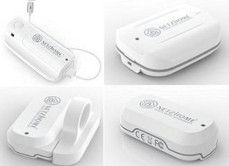
-
In my last tutorial I created a Weather Station using Arduino and NodeMCU using DHT11 or DHT22 temperature and humidity sensor and displayed it using an OLED Display. In this tutorial, I am going create a Peg-Box using the same board but with a little bit of twist. In this setup, I am going to send the Temperature and Humidity readings to my Raspberry Pi based home server and store it in a MySQL database. The data can then be viewed using PHP and Google Charts, on a Mobile Phone or a PC connected to the home network. Circuit Diagram The setup is very simple. The temperature and humidity sensor sends the collected data to the NodeMCU on pin D3. NodeMCU then sends the data over WiFi to the Raspberry Pi, which is then saved in the MySQL database. The Yellow LED, which is the status indicator flashes every second and is connected to D6 pin of the NodeMCU. The Blue LED connected to pin D5, lights up when NodeMCU sends the temperature and humidity readings to the database. If you are planning to install this box somewhere inside the house, then you can also add an OLED display and display the readings on it. The Board So, this is how my board looks like in 2d and 3d. There are 3 breakout boards in this 100cm x 100cm assembly. Each board can be used with either Arduino or NodeMCU and DHT11 or DHT22 sensor or sensor module. Temperature and humidity readings can be collected using either a DHT11 or DHT22 Module or by using one of these sensors with a 10K resistor. The bottom section of the board is for the OLED display. The attached gerber is bit different from what you see on screen. I made some modifications in the final version and moved the sensors a bit far from the microcontrollers. Component Assembly Lets start by soldering the female pin-headers to the board. The pin-headers will house the NodeMCU in it. Next, lets soldered few more pin-headers for the LEDs, DHT11 sensor and the OLED display. Before installing the circuit in the peg-box, lets hook up the OLED Display and make sure everything works as expected. Boom, nailed it. The Code The code starts by including all the libraries and by defining all the constants and variables that will be used throughout the program. Then there are two functions SendIamAlive() and SendTemperatureAndHumidity() which sends heartbeat and the data read from the temperature sensor to the database server. The ReadDHTSensor() function reads the data from the DHT11 or DHT22 sensor. In the setup section we first setup the WiFi and then send a SendIamAlive() message to the server advising that it is back up and running. Then in the loop section the microcontroller send a heartbeat every minute using the SendIamAlive() function and if the time elapses it sends the humidity and temperature data using the SendTemperatureAndHumidity() function. The White LED flashes every seconds and the Blue LED turns on when the device sends the temperature and humidity data to the database server. MySQL So,the data sent by the NodeMCU over WiFi is saved in the MySQL database hosted on a RaspberryPi 4. Here you can see, the microcontroller sends the data every 30 minutes (you can change the frequency) which is then saved in the MySQL database. The data saved on the Pi's MySQL database can then be used to generate various different types of graphs either by using google charts or any other 3rd party application. It totally depends on you how you want to present it. 3D Design Now, lets look at the design of the peg-box. Using freely available pallet planks, I designed the body of the box. The pallet planks I am using are 160cm x 9cm x 2cm (length, width and thickness). So, the rest of the measurements will be based on that. The top bit of the peg-box will house the microcontroller and the sensors in it. Putting it on the top prevents the electronics from adverse climatic conditions. The back bit will stick to wall and hence we don't need to cover it up. You can either put the pegs straight in the front bin or throw it to the top bit, from where it will slide down to the front bin. The sliding design with an opening in the front will prevent rainwater from accumulating inside the bin. This mechanism will keep the bin dry throughout the year. Woodworking Using 2 hammers I am dismantling the pallet. My aim is to reuse all the nails used in building this pallet so that, I can use them in building my project. After that, I sanded the pallet planks to give them a nice and smooth texture. Then using a chop-saw or a hand-saw I extracted all the pieces of wood required for building this project. As mentioned earlier, my pallet plank are 9cm wide and hence, all the onscreen measurements are based on that. Final Assembly Using wood-glue I am joining all pallet planks used in making the box. I got a bit too excited and accidentally deleted one of my recordings. So, I am using 3D animation to show you guys how I joined the two sides of the box. I used a plywood board to created the base of the bin. I glued few cylindrical wooden sticks on the roof of the box. To be very frank these sticks changed the entire outlook of the peg-box. Coloring Since my aim is to install the peg-box outside the house, I have to make sure that I apply multiple coats of paint on the box to avoid the pallet wood from rotting. I applied 3 coats of paint on the entire setup and insulated all the holes that I found using wood putty. So, this is how it looks like. The electronics bit will stay hidden under the roof of the box. Ha ha, Don't worry, I will obviously insulate them and make them weather-proof before installing them on the wall. Installation Now the next thing you need to do is to find a spot where you want to install this unit. I am installing this near my clothesline, however you may want to install it in your pantry or behind a door or something like that. It totally depends on how much space you have and where you want to install it. I am using metal frame hangers to hang this on the wall. Place the unit against the wall, and using a pencil mark the points where you want to drilling the holes. Now, using a hammer drill, drill the holes in the wall. Then, put the wall plugs in the wall and then use a screw driver to install the screws. Alright so, that's it. This unit is now all set to hold all my pegs in it. Demo So, this how my final setup looks like. Do comment and let me know if there are any scopes of improvement. Thanks Thanks again for checking my post. I hope it helps you. If you want to support me subscribe to my YouTube Channel: https://www.youtube.com/user/tarantula3 Blog Posts: 1. Peg Box 2. DHT11 & DHT22 3. OLED Tutorial Video references: 1. Peg Box 2. DHT11 & DHT22 3. OLED Tutorial Resources: Gerber Schema 3D Model Code: Code (Arduino + PHP + MySQL DB) Code_With_OLED_Arduino Code_With_OLED_NodeMCU Code_With_PHP_NodeMCU Libraries: DHTStable.h SSD1306.h Adafruit display library Adafruit GFX library Support My Work: BTC: 1M1PdxVxSTPLoMK91XnvEPksVuAa4J4dDp LTC: MQFkVkWimYngMwp5SMuSbMP4ADStjysstm DOGE: DDe7Fws24zf7acZevoT8uERnmisiHwR5st ETH: 0x939aa4e13ecb4b46663c8017986abc0d204cde60 BAT: 0x939aa4e13ecb4b46663c8017986abc0d204cde60 LBC: bZ8ANEJFsd2MNFfpoxBhtFNPboh7PmD7M2 Thanks, ca again in my next tutorial.
-
I love mining and I truly believe that blockchain and digital currencies will one day change the world. Cryptocurrency has played a significant role in my life and has made me a morning person, ha ha. Miners require 24 x 7 access to the Internet. Recently, I went on a short business trip and my router for some stupid reason stopped working. I lost complete access to my home network and my miners. When I returned from my trip, my only aim was to fix this issue by creating an "Internet Hardware Watchdog" that reboots the router whenever something silly happens to it. Note: If you do any work with "mains power" such as 120v or 240v AC power wiring, you should always use proper equipment and safety gears and determine whether you have adequate skill and experience or consult a Licensed Electrician. This project is not intended for use by children. The Logic Let me first explain the logic to you. In a nutshell, in this setup I am going to ping "www.google.com" and as soon as the ping drops I will reboot the router. To achieve this, the NoduMCU first connects to the WiFi network and then pings 8.8.8.8 (www.google.com). If it receives a successful ping, one out of the 3 blue LED patterns is displayed. If the ping fails, 5 more retries are given before rebooting the router. The reason I am NOT rebooting the router straightaway is to avoid false positive ping fail responses. However, once the "fail_count" counter becomes 5, NodeMCU turns off the router by pulling the armature of the relay module. The armature of the relay is held for 15 seconds before releasing it so that the router is properly power cycled. Once the armature is released, the system waits for a minute before sending the next ping request. This gives enough time to the router to successfully perform its POST activities. The above steps are then endlessly repeated in the loop section of the code. Components Required For this project we need: NodeMCU Stepdown Converter Relay Module 2 x Red LEDs 3 x Blue LEDs 100Ω Resistor Power Plug and a Power Socket Schematic Now, let's put the components together exactly the way I have shown in the schematic diagram. Be very careful while handling AC Main Power sockets and cables. The Stepdown Converter powers the NodeMCU and the Relay Module. LEDs are connected to the Digital pins of the microcontroller. The relay acts as a switch and switches on or off the router based on the ping response. Please make sure you check the pins of your relay module before hooking it up to the circuit. The Board So, this is how my board looks like in 2D and 3D. I basically have created a replica of the NodeMCU Prototyping Board which you can buy from AliExpress for about $4 to $6. Components Assembly Lets start by soldering the NodeMCU to the board. Since I care a lot about my Sensors and Microcontrollers, I am not going to solder them directly to the board. Instead I am soldering 'female pin headers' to the board which will house all the sensors and the microcontrollers in them. I initially thought of soldering the LEDs directly on the board however something clicked in my mind and I went ahead and soldered them on a separate perfboard and then soldered the perfboard to the NodeMCU development board. Well, this was totally unnecessary. Once the LEDs were in place, my next step was to solder the step-down-converter and the relay-module to the board. If you want to know how I created this relay module, please check out my tutorial no. 19 DIY Relay Module : https://www.youtube.com/watch?v=3n69b4sdDjk the video and the blog post links are in the description below. Next, I made a hole in the transparent box and glued the power socket into it. Well I created a bit of mess while gluing the socket and accidentally glued the box on to my dining table, silly me. I also drilled a hole at the back of this box, for the cable that will connect to the AC Main power supply. Pretty much that's it. Once again, I would like to warn you guys: If you do any work with the "main power" such as 110v or 240v AC, you should always use proper equipment and safety gears and determine whether you have adequate skill and experience or consult a Licensed Electrician. This project is not intended for use by children. To conclude the setup, I added a small skull inside the acrylic box. This skull has been sitting on my desk just collecting dust for over a year, ha ha. The Code Now, let's have a look at the code. You can download the code and other resources from the links provided in the description below. To Run the attached code you need to download and install the "ESP8266Ping" library. You can either download it from GitHub or from the link provided in the description below. Unzip and copy the archive to the Arduino's Library Folder and change the board type to ESP8266 in the Arduino IDE and select NodeMCU. The code starts by including all the libraries and variables on top. Then in the setup() section I have defined all the pin modes and have made a connection to the WiFi router. In the loop() section I am performing a ping test and based on the test result I am either blinking the blue LEDs or power cycling the router. Thanks Thanks again for checking my post. I hope it helps you. If you want to support me subscribe to my YouTube Channel: https://www.youtube.com/user/tarantula3 Blog Posts: Internet Hardware WatchDog : https://diy-projects4u.blogspot.com/2021/12/internet-hardware-watchdog.html DIY Relay Module : http://diy-projects4u.blogspot.com/2020/08/diy-relay-module.html Video: Internet Hardware WatchDog : DIY Relay Module : https://www.youtube.com/watch?v=3n69b4sdDjk Other Resources: Code: https://drive.google.com/file/d/1HyTUMUBDK0neO854XMl3dyy5ceoeTImw/view?usp=sharing ESP8266Ping Library : https://github.com/dancol90/ESP8266Ping.git ESP8266Ping Library : https://drive.google.com/file/d/1uFfY5wW7-oWRNjP_XaBj2IM189M1n1FK/view?usp=sharing Schema: https://drive.google.com/file/d/1gn2ZhMp5Uz4YDv5GjxgIq1rtzh-21Rwe/view?usp=sharing Gerber File: https://drive.google.com/file/d/1l0bszJ0AV7S9s-y9jTWGcw9MrWayVJxZ/view?usp=sharing Flowchart: https://drive.google.com/file/d/1CL3g0nT1IZfdL8MZqN_PB-mKC9k_JfWH/view?usp=sharing Support My Work: BTC: 1M1PdxVxSTPLoMK91XnvEPksVuAa4J4dDp LTC: MQFkVkWimYngMwp5SMuSbMP4ADStjysstm DOGE: DDe7Fws24zf7acZevoT8uERnmisiHwR5st ETH: 0x939aa4e13ecb4b46663c8017986abc0d204cde60 BAT: 0x939aa4e13ecb4b46663c8017986abc0d204cde60 LBC: bZ8ANEJFsd2MNFfpoxBhtFNPboh7PmD7M2 Thanks, ca again in my next tutorial.
-
 Materials AmebaD [RTL8722 CSM/DM] x 2 Example Introduction BLE connections use a server client model. The server contains the data of interest, while the client connects to the server to read the data. Commonly, a Bluetooth peripheral device acts as a server, while a Bluetooth central device acts as a client. Servers can contain many services, with each service containing a some set of data. Clients can send requests to read or write some data and can also subscribe to notifications so that the server can send data updates to a client. In this example, a basic battery client is set up on the Ameba Bluetooth stack. The client connects to another Ameba board running the corresponding BLE battery service to read the battery level data. Procedure On the first Ameba board, upload the BLEBatteryService example code and let it run. For the second Ameba board, open the example “Files” -> “Examples” -> “AmebaBLE” -> “BLEBatteryClient”. Upload the code and press the reset button on Ameba once the upload is finished. Open the serial monitor and observe the log messages as the Ameba board with the battery client scans, connects, and reads data from the Ameba board with the battery service. Highlighted in yellow, the Ameba board with the battery client first scans for advertising BLE devices with the advertised device name “AMEBA_BLE_DEV” and the advertised service UUID of 0x180F representing the battery service. After finding the target device, the Ameba board with the battery client forms a BLE connection and searches for a battery service on the connected device, highlighted in blue. With the client connected to the service, the battery client begins to read data using both regular data reads and notifications, highlighted in green. Code Reference BLEClient is used to create a client object to discover services and characteristics on the connected device. setNotifyCallback() is used to register a function that will be called when a battery level notification is received. BLE.configClient() is used to configure the Bluetooth stack for client operation. addClient(connID) creates a new BLEClient object that corresponds to the connected device. For more resources: If you need additional technical documents or the source code for this project. Please visit the official websites and join the Facebook group and forum. Ameba Official Website: https://www.amebaiot.com/en/ Ameba Facebook Group: https://www.facebook.com/groups/amebaioten Ameba Forum: https://forum.amebaiot.com/
 -

arduino HOW TO SETUP THE ARDUINO MKR 1300
Enrg Tech posted a topic in Electronic Projects Design/Ideas
The Arduino MKR 1300 comes equipped with the ATMEL SAMD21 bridged with a LoRa module thus allowing for remote IoT applications for instance mining, off-shore rigs, and farms. It has been designed to integrate SAMD21’s low power consumption and high performance while maintaining Arduino’s ease of use. HOW TO SETUP THE ARDUINO MKR 1300.docx -
Infrared remote controllers are everywhere around us. The majority of home appliances are controlled using infrared remote controls. In this article/video, we learn to build a device that can decode (almost) any IR remote control and use the instructions to switch the relays (loads). So we can use this feature in a variety of applications without buying a new IR remote control and expensive hardware, such as turning ON/OFF the lights, opening/closing the curtains, ... etc. I have used an ATTiny85 microcontroller as the heart of the circuit. The device can record up to three IR codes in the EEPROM memory and switch 3 separate devices. Each relay can handle the currents up to 10A. The load switching mechanism (momentary ON/OFF, toggling, .. etc) can be programmed by the user. I used Altium Designer 21.4.1 and the SamacSys component libraries (SamacSys Altium Plugin) to design the Schematic and PCB. I also used the Siglent SDS2102X Plus/SDS1104X-E to analyze the IR signals. The device works stable and reacts well to the transmitted IR signals. So let’s get started and build this puppy! References Article: https://www.pcbway.com/blog/technology/Infrared_Remote_Control_Decoder___Switcher_Board.html [1]: L7805 datasheet: https://www.st.com/resource/en/datasheet/l78.pdf [2]: TS2937CW-5.0 datasheet: http://www.taiwansemi.com/products/datasheet/TS2937_E15.pdf [3]: VS1838 infrared receiver module datasheet: https://www.elecrow.com/download/Infrared%20receiver%20vs1838b.pdf [4]: FDN360P datasheet: https://www.onsemi.com/pdf/datasheet/fdn360p-d.pdf [5]: ATTiny85-20SUR datasheet: http://ww1.microchip.com/downloads/en/DeviceDoc/Atmel-2586-AVR-8-bit-Microcontroller-ATtiny25-ATtiny45-ATtiny85_Datasheet.pdf [6]: Si2302 datasheet: https://www.vishay.com/docs/63653/si2302dds.pdf [7]: Altium Designer electronic design CAD software: https://www.altium.com/altium-designer [8]: SamacSys Altium plugin: https://www.samacsys.com/altium-designer-library-instructions [9]: ATTiny85 schematic symbol, PCB footprint, 3D model: https://componentsearchengine.com/part-view/ATTINY85-20SUR/Microchip [10]: TS2937-5.0 schematic symbol, PCB footprint, 3D model: https://componentsearchengine.com/part-view/TS2937CW-5.0%20RP/Taiwan%20Semiconductor [11]: L7805 schematic symbol, PCB footprint, 3D model: https://componentsearchengine.com/part-view/L7805CV/STMicroelectronics [12]: SI2302 schematic symbol, PCB footprint, 3D model: https://componentsearchengine.com/part-view/SI2302DDS-T1-GE3/Vishay [13]: FDN360P schematic symbol, PCB footprint, 3D model: https://componentsearchengine.com/part-view/FDN360P/ON%20Semiconductor [14]: ATTinyCore: https://github.com/SpenceKonde/ATTinyCore [15]: IRRemote library: https://github.com/Arduino-IRremote/Arduino-IRremote [16]: Siglent SDS2102X Plus oscilloscope: https://siglentna.com/products/digital-oscilloscope/sds2000xp-series-digital-phosphor-oscilloscope [17]: Siglent SDS1104X-E oscilloscope: https://siglentna.com/digital-oscilloscopes/sds1000x-e-series-super-phosphor-oscilloscopes
-
Have an awesome project in mind using some LEDs. In that project I will be using some LED Fading Effect and few LED Chaser Circuits. But before jumping onto that, I thought I should create a short tutorial and show you guys how to fade a LED with or without an Arduino automatically or manually using a potentiometer. Video: https://youtu.be/IIUsdICycOw Sponsors This video is sponsored by PCBWay. PCBway: only $5 for 10 pcbs from https://www.pcbway.com/?from=CZcouple PCBWay specialize in manufacturing of very high quality, low-volume, colored PCBs at a very budgetary price. In addition to the standard PCBs, you can also order Advanced PCBs, Aluminum PCBs, FPC/Rigid-flex PCBs. They also provide PCB assembly and other related service which can meet your needs to the greatest extent. The ordering process from PCBWay is very easy. Once I had my design ready, I just had to upload the gerber file to the PCBWay's website and select the type, color and any other customization that I want and then just send it for fabrication. For my project, I choose the black color. PCBWay ships from china to most of the countries of the world within 3 to 7 business days. Talking about the quality, its absolutely mind-blowing. Without Arduino Lets first create the fader circuit without an Arduino. The base of this circuit is an operational amplifier IC named LM358. In this circuit, initially, the LED slowly glows with increasing brightness & after reaching its maximum brightness, the LED slowly dims its brightness and the process continues. Automatic Fading Components Required For the Non-Arduino bit we need: 1 x LM358 IC 1 x BC547 Transistor 1 x 0.47µF Capacitor 2 x 4.7KΩ Resistors 1 x 22KΩ Resistor 1 x 10KΩ Resistor 1 x 4.7MΩ Resistor 1 x 220Ω Resistor 1 x LED and a 9V Battery How This Circuit Works To get the fading effect we need to generate a series of triangular waves. Because of the triangular waves, the LED starts glowing slowly and then slowly dims off and the cycle continues. This setup is done using the LM358 IC. LM358 is a dual operational amplifier (Op-Amp) IC, integrated with two op-amps powered by a common power supply. Pins 1, 2, and 3 are one op-amp channel, and pins 5, 6, and 7 are the 2nd op-amp channel. As the capacitor charges and discharges the state of the PIN 3 switches from high to low and based on that the PIN 2 of the op-amp obtains the desire output. If you want to know more about this IC, please check out my "Tutorial No 21 : DIY - IR Module" : https://youtu.be/_M8FQIPi1qk. So, basically the op-amp here is used for voltage level detection. In this circuit, we are applying a voltage on positive pin (PIN-3) and the voltage to be detected is applied at negative pin (PIN-2). The transistor acts as a signal amplifier. You will need this if you are attaching a cluster of LEDs however for just 1 LED you can simply remove it. The Board So, this is how my board looks like in 2D and 3D. There are 15 breakout-boards in this 100cm x 100cm assembly. Component Assembly Now, lets solder all the components to the board. Lets first solder all the resistances to the board. Then lets solder the transistor followed by the capacitor to the board. After that lets solder the LED and the female pin header. To conclude the setup, lets solder the IC base and then install the IC into it. Demo So, this is how it looks like. Good thing about LEDs is that they can be easily controlled as compared to the traditional light bulbs. Which means you can easily change their intensity based on your need. Just by making a slight modification to this circuit you can change the brightness of a LED Lamp when someone walks in or out of a room. Manual Fading Using PWM Now, if you want to get the same dimming effect but want to manually control the intensity, you will have to find a way to modulate the pulse sent to the LED or group of LEDs using a potentiometer. I am going to do this by generating PWM Signals. What is PWM? Pulse Width Modulation, or PWM, is a technique for getting analog results with digital means. PWM value varies from 0 to 255. The bigger the value of PWM, the brighter the LED is and vice versa. - If PWM = 0, it is same as GND, so the LED will be OFF - If PWM = 255, it is same as VCC, so the LED will be fully ON To get varying analog values, you change, or modulate, that pulse-width. If you repeat this on-off pattern fast enough with an LED, the result is as if the signal is a steady voltage between 0 and 5v controlling the brightness of the LED. In this setup, we are going to use the 555 Timer IC in Astable mode (A free-running multivibrator that has NO stable states but switches continuously between two states this action produces a train of square wave pulses at a fixed known frequency) to generate the PWM Signals. 555 Timer IC will vary the voltage delivered to the LEDs to achieve the Dimming effect of the LED. Components Required For this setup we need: 1 x 555 Timer IC 1 x LED 1 x 220Ω Resistor 2 x 1N4007 Diodes 1 x 50KΩ Potentiometer 1 x 10nF Capacitor 1 x 100nF Capacitor and a 5V Battery How This Circuit Works Based on the charging and discharging timings of the Capacitor, a PWM Signal is generated at PIN 3 (OUT PIN) of the 555 Timer IC. The output is then sent to the LED to produce the dimming effect. Demo So, this is how it looks like. By rotating the knob of the 10K Pot we can adjust the brightness of the connected LED. With Arduino Now, lets repeat these setups using an Arduino. The beauty of Arduino is that it has 6 digital pins that can be used as PWM outputs (3, 5, 6, 9, 10, and 11). PWM signals are sent using the analogWrite() function by passing a value between 0 - 255. - analogWrite(255) requests a 100% duty cycle (always on), - and analogWrite(127) is a 50% duty cycle (on half the time), and so on. Components Required For this setup we need: Arduino UNO/Nano whatever is handy 1 x Breadboard 1 x LED 1 x 220Ω Resistor 1 x 10KΩ Potentiometer Automatic Fading Connect the positive leg of your LED to the digital output PIN9 of your Arduino through a 220Ω resistor. Connect the negative leg directly to the GND. That it, that's how simple it is. The Code After declaring PIN 9 as LedPin, and setting up the pinMode in the setup() section, we are going to loop through and dim the LED in the loop section. By gradually increasing the PWM value from 0 to 255, and then back to 0 we can get the fading effect. In this sketch, the PWM value is set using a variable called 'brightness'. Each time in the loop, it increases by the value of the variable 'fadeAmount'. If brightness is at either extreme of its value (either 0 or 255), then 'fadeAmount' is changed to its negative. So, if the fadeAmount is 5, then it is set to -5 and if it is -5, then it is set to 5. The next time through the loop, this change causes brightness to change its direction. A delay is added to control the speed of the fading effect. Demo So, this is how it looks like. Manual Fading Connect the positive leg of your LED to the digital output PIN6 of your Arduino through a 220Ω resistor. Connect the negative leg directly to the GND. Connect the left (or right) pin of the 50KΩ PoT to VCC and then connect the right (or left) pin of the PoT to the GND. Now, connect the 'data' pin of your potentiometer to the Analog PIN 'A0' of the Arduino. In this circuit, the potentiometer is working as a voltage divider. One of the outer pins is connected to the GND, the other to Vcc and the middle pin is the voltage output. The wiper position in this setup determines the output voltage. Now, lets have a look at the code. The Code Based on my setup, I set the LedPin as 6 and Potentiometer pin Pot as A0. Another variable 'Knob' is used to read and store the value of the potentiometer. pinMode of the LedPin is set to OUTPUT and we don't need to do anything for the PoT as its default value is already set as input. In the 'loop()' section I am first reading the value of the PoT using the 'analogRead()' function and then mapping its value between 1 to 255. A potentiometer intakes a value between 1 and 1024, but in our setup it has to be between 1 to 255. The 'map()' function divides the value read from the potentiometer into equal intervals of 1/255, which is then sent to the LED using the 'analogWrite()' function. Demo So, this is how it looks like. Thanks Thanks again for checking my post. I hope it helps you. If you want to support me subscribe to my YouTube Channel: https://www.youtube.com/user/tarantula3 Full Blog Post: https://diy-projects4u.blogspot.com/2021/02/led-fader-with-or-without-arduino.html Video: https://youtu.be/IIUsdICycOw Gerber File: 1. Gerber : https://drive.google.com/file/d/1w1hHZBFsXQR74ZTn04097awaAUqMndJi/view?usp=sharing The Code: 1. Automatic Fading : https://drive.google.com/file/d/1hab3sISIlurrPQBat80OLb90RXqQKzLZ/view?usp=sharing 2. Manual Fading Using PoT : https://drive.google.com/file/d/1TzXdVO5lVjPNaw_NPSUexIye3WZGJ6cj/view?usp=sharing Sketches: https://drive.google.com/file/d/1_WtmESof7kSyuJ_cmkkFZ8E8mdQXl3Z9/view?usp=sharing BTC: 1M1PdxVxSTPLoMK91XnvEPksVuAa4J4dDp LTC: MQFkVkWimYngMwp5SMuSbMP4ADStjysstm DOGE: DDe7Fws24zf7acZevoT8uERnmisiHwR5st ETH: 0x939aa4e13ecb4b46663c8017986abc0d204cde60 BAT: 0x939aa4e13ecb4b46663c8017986abc0d204cde60 LBC: bZ8ANEJFsd2MNFfpoxBhtFNPboh7PmD7M2 Thanks, ca again in my next tutorial.
-
A Chaser Circuit consists of a clocked IC or other electronic unit like an Arduino that drives an array of LEDs in such a way that individual LEDs (or small groups of LEDs) turn on and off in a predetermined and repeating sequence, thus producing a visually attractive display in which one or more ripples of light seem to repeatedly run through a chain or around a ring of LEDs. In this tutorial I am going to create 3 chaser circuits using Arduino and IC4017 decade counter. https://youtu.be/F6V1AjESWbU Sponsors This video is sponsored by PCBWay. PCBway: only $5 for 10 pcbs from https://www.pcbway.com/ PCBWay specialize in manufacturing of very high quality, low-volume, colored PCBs at a very budgetary price. In addition to the standard PCBs, you can also order Advanced PCBs, Aluminum PCBs, FPC/Rigid-flex PCBs. They also provide PCB assembly and other related service which can meet your needs to the greatest extent. The ordering process from PCBWay is very easy. Once I had my design ready, I just had to upload the gerber file to the PCBWay's website and select the type, color and any other customization that I want and then just send it for fabrication. For my project, I choose the black color. PCBWay ships from china to most of the countries of the world within 3 to 7 business days. Talking about the quality, its absolutely mind-blowing. Using IC555 and IC4017 Lets first create the chaser circuit using the IC4017 decade counter and IC555 timer IC. Components Required For the Non-Arduino bit we need: 2 x 4017 Decade Counter IC 1 x 555 Timer IC 1 x 10 K Potentiometer 1 x 1 Kilo Ohm Resistor 1 x 100 Ohm Resistor 1 x 100 MFD Capacitor 20 x Zener Diodes and 10 x Red LEDs Circuit Diagram 1. Forward Chaser The circuit is very simple. The 555 Timer IC operates as a clock oscillator or clock generator. The output on PIN-3 goes high causing a shift. The signal from the 555 IC clocks the 4017 decade counter. Output of 555 timer IC on PIN-3 is given as an input to 4017 IC through PIN-14. Whenever a pulse is received at the input of IC 4017, the counter increments the count and activates the corresponding output PIN. This IC can count upto 10, so we have attached 10 LEDs to the circuit. By increasing or decreasing the value of resistance of the 10K pot we can adjust the speed of the chaser circuit. Since only one LED will be turned on at a given time, I have attached just one 220ohm current limiting resistor to the cluster of LEDs. Demo: So this is how it looks like. 2. Forward Reverse Chaser using 2 x IC4017 Now, to give the forward and reverse effect we are attaching another 4017 IC to this circuit. If lets say the 1st IC connects from 1 to 10 (left to right) then the second one should connect from 10 to 1 (right to left). However, now we cannot connect the counter ICs directly to the LEDs as we did before. We have to use Diodes to stop the reverse flow of current to the 2nd IC. We have also lowered the value of the current limiting resistor to 100ohms as at a given time 2 LEDs will be on, one running from left and one from the right hand side. Demo: Now lets do a quick test. By lowering the speed I can get the desired forward and reverse effect. By removing one of the 4017 ICs we can get the effect that I demonstrated in the previous example. 3. Forward Reverse Chaser using 1 x IC4017 To get a forward reverse effect using one 4017 IC we need to connect 8 diodes to the circuit. The 1st and the 6th LED will be directly connected to the IC4017. The LEDs at the far end will get signals from only one pin however the one in the middle will receive signals from 2 x pins and hence we need diodes to stop the reverse flow of the current. Demo: So this is how it looks like. Using Arduino Now, I am going to repeat the same setup using an Arduino. Components Required For the Arduino bit we need: 1 x Arduino Uno/Nano (whatever is handy) 1 x 220 Ohm Resistor 10 x Red LEDs Few Connecting Cables The beauty of using an Arduino is that the setup remains the same for all the previously shown circuits, the only thing that changes is the code. So, I am going to use this simple setup for the rest of the tutorial. Circuit Diagram 1. Forward Chaser Code: The code for the forward chaser is very simple. Start by defining the constants and the global variables that will be used throughout the code. Then in the setup section define the pin modes. Now, in the loop section we are going to start by turning off all the LEDs followed by turning one LED on at a time. A counter is used to tell the loop which LED to turn on in the next cycle. Once the value of the counter reaches 10 (the maximum number of LEDs) the counter resets to 1 and the 1st LED lights up and the cycle continues. Demo: So this is how it looks like. 2. Forward Reverse Chaser Code: The code is same as the previous setup. The only thing that changes is the function that deals with the LEDs. In this setup we cycle through LED 1 to LED 10 and then reverse from LED 9 to LED 1. The counter resets when the max count is reached. Demo: So this is how it looks like. 3. Left-Right Chaser Code: The setup is exactly the same as the previous two setups. This function is the one which turns on the LEDs at the two far ends and then the one before that and likewise until they cross each other. The counter is reset when the max count is reached. Demo: So this is how it looks like. PCF8574 8-bit GPIO Port Extender Using a PCF8574 8-bit GPIO Port Extender we can add even more LEDs to this setup. PCF8574 becomes a life saver when you run out of pins on your Arduino. This "GPIO (General Purpose Input Output) pin extender" provides an additional 8 pins (P0 ~ P7) which can be used to 'output a signal' or 'read a signal as an input'. These modules run on the I2C bus, and if daisy-chained you can connect upto 8 of these devices in a project. Each device will give us an additional 8-bits of GPIO enabling 64 GPIOs in total. To know more about this IC please check out my tutorial number 10 : "PCF8574 GPIO Extender - With Arduino and NodeMCU". Thanks Full Blog Post: https://diy-projects4u.blogspot.com/2021/01/led-chaser-circuits-using-ic4017-and.html Video: https://youtu.be/F6V1AjESWbU Gerber File: 1. https://drive.google.com/file/d/108EUNylmearJgU_4qSlxNr9GAPGrLGRh/view?usp=sharing Code: 1. Forward: https://drive.google.com/file/d/1bw1la5oRMWZRXsfYJ41qNbCoEkJsZHBM/view?usp=sharing 2. Forward Reverse: https://drive.google.com/file/d/1Oag8kxbvfxZg7StFrYzWwtcqQx6okwzd/view?usp=sharing 3. Left Right: https://drive.google.com/file/d/17ZEsKU3OFrcjaJpvyUJMQbHQ-lznbp0H/view?usp=sharing Sketch: 1. With Arduino: https://drive.google.com/file/d/1YHWvpkDbGbGVHwX65HwvwS3_JyFwZdK9/view?usp=sharing 2. Without Arduino: https://drive.google.com/file/d/1LdxcS1BXf3GtQTRhWCoCZKm6ppRwsc5k/view?usp=sharing BTC: 1M1PdxVxSTPLoMK91XnvEPksVuAa4J4dDp DOGE: DDe7Fws24zf7acZevoT8uERnmisiHwR5st LTC: LedWPdTaUzr5iaJx8garkcykSs1DZU1FAx ETH: 0xB62a901Ee6cE24f3153CA6ae565C2A6533066faA BAT: 0xB62a901Ee6cE24f3153CA6ae565C2A6533066faA BCH: 14xJhpswSAQi375S39yDFsrBFtDoiLVX1J
-
With a BLE5.0 & Dual-band WiFi microcontroller, you will never have to worry about re-compiling the code just to change the WiFi ssid and password. Ameba RTL8722 is a BLE5.0 and dual-band WiFi (2.4G & 5G) Iinternet-of-Things (IoT) developing platform that suit the need for many IoT application scenarios. Taking advantge of its BLE + WiFi combination, we can easily change Ameba's WiFi setting and save us great deal of time. Take a look at the short video below to learn more https://youtu.be/TA4A-VXbImo
-
ameba Creating WiFi Access Point using MCU -- Ameba Arduino
MENG XI posted a topic in Electronic Gadgets
Most of time when we use WiFi, we only use our WiFi device as a "station"(STA) that mainly receive information sent from "access point" (AP). Ameba Microcontroller from Realtek can not only connect to WiFI as a station, but also broadcast its own signal and become an AP, here is how, In AP mode, Ameba can accept at most 3 station connections, and can be set to open mode or security mode (WPA2). Preparation Ameba x 1 Example In this example, we turn on the AP mode of Ameba and connect station to Ameba. Open the WiFi AP example, "File" -> "Examples" -> "AmebaWiFi" -> "WiFiAPMode" In the snippet highlighted in yellow, fill in your SSID, PASSWORD and CHANNEL. The snippet highlighted in pink is the API we used to turn on the AP mode in security mode. If you want to turn on the AP mode in open mode, please modify the code to status = WiFi.apbegin(ssid, channel); Then upload the sample code and press reset, and you can see related information shown in serial monitor. In the figure below, we show the messages shown in serial monitor when two stations connect to Ameba AP in open mode: In the figure below, we show the messages shown in serial monitor when a station connects to Ameba AP in security mode: